Technology (IJRASET)
Significance of Baffles in Fluid Flow and Heat
Transfer
R. D Mishra1, P. K Chandrakar2
Student of Thermal Engineering, S.S.G.I (S.S.T.C ) Junwani Bhilai, India
Abstract: In the field of fluid flow and heat transfer utilization of complex geometries in from of extended surface such fins, baffles, artificial roughness gaining attention of researchers due to having significant application in the field of heat and mass transfer, specially baffles are exercised in various thermal application in order to increase thermal performance and hydrodynamic performance characteristics. . Application such as Heat exchanger, solar air heater, photovoltaic ducts or channel, nuclear reactor etc. these baffles leads to obstacle in flow through which turbulence generates which help in promotion of fluid mixing, heat transfer, enhancement un friction factor etc.
This work focuses on hydrodynamic performance analysis of pipe with presence of fragmented baffles. The performance characteristics of baffled pipe have been compared with smooth pipe for a wide range of Reynolds number. The governing equation has been solved by using ANSYS Fluent and for high Reynolds number k-turbulence model has been used along with SIMPLE algorithm. The obtained results have been compared with available literature and show good agreement with the computational an experimental work.
Keywords: fins , fragmented baffles, Reynolds number.
I. INTRODUCTION
In a field of fluid dynamics and heat transfer turbulent flow over rough surfaces has been a topic of increasing interest. This type of flow can be examined in various engineering applications such as nuclear reactor, heat exchangers, wind tunnel, turbine blade, fluid catalytic cracking & air foil. The flow through pipes is of significant industrial importance and is representative of a more general class of wall-bounded flows including boundary-layers and channels. Pipe flow occurs in a variety of settings from the movement of oil in intercontinental pipelines to the flow through arteries and capillaries. The particularly simple geometry of the flow led to many experimental studies resulting in the exploration, among others, of Osborne Reynolds on transition more than 125 years ago. The flow exhibits three different regimes: Laminar, Transitional & Turbulent. At the wide range of Reynolds number representative of industrial applications, the flow is commonly turbulent. The Reynolds number is defined as Re = ρD/Ȟ, where U¯ is the bulk velocity, D is Pipe diameter, and Ȟ is kinematic viscosity of the fluid.
The transition from an organized laminar state to a disorganized three-dimensional (3D) turbulent state in pipe flow causes a significant increase in the pumping power required to move the fluid along the pipe. The transition occurs naturally once the Reynolds number is increased past a critical value depending on the flow facility, even though pipe flow is linearly stable for all Reynolds numbers. The turbulent state appears disorganized, yet exhibits coherent structures that play an important role in the dynamics, and are responsible for sustaining turbulence. Coherent structures are defined by Berkooz as organized spatial features which repeatedly appear and undergo a characteristic temporal life cycle. The structures can be observed in both the velocity and vorticity Fields.
Turbulent pipe flow is often disintegrated into a mean component U and fluctuations about the mean u, which is called a Reynolds decomposition of the flow. The fluctuations arise due to the coherent structures & disorganized motions. Understanding the generation and maintenance of the turbulent fluctuations, and the change in mean flow during transition (which is related to the drag increase) is one of the last unsolved problems in classical physics, as discussed by Gad-el-Hak in the editorial preceding the article by George & Castillo (1997). New insight gained into the maintenance of fully developed turbulence or into pipe flow transition is expected to result in the identification of more efficient approaches to manipulate the flow. Typical flow manipulations include suppressing turbulence or decreasing the drag down to a level closer to laminar flow drag.
Technology (IJRASET)
dimensional, and that it depends only on the wall- normal distance. For various general flows, comprises of transitioning and turbulent flows, the NS equations need to be drastically simplified in order to make analytical progress. One such simplification is to linearize the equations around the laminar velocity profile, under the assumption that the perturbations of the laminar state are infinitely small, leading to an Eigen value analysis of the flow.
II. LITERATURE SURVEY
A. Ko and Anand 2003 experimentally investigates the heat transfer coefficients in uniformly heated rectangular channel with wall mounted porous baffles. It has found that employing porous baffles heat transfer can be enhanced by 300 compared to heat transfer in straight channel with no baffles. Moreover, they also developed a correlation for heat transfer enhancement ratio.
B. Chiu and James 2006 investigate the effect of axial baffles in non-circular channeled membranes on the critical flux with various configurations of inserts to overcome pressure drop. Moreover, comparative analysis between the different shapes of inserts has been carried out and found that helical baffles having two turns per 25 mm results in optimum flow conditions leading to the best performance in terms of the critical flux in the helical baffle series. But the flux enhancement significantly decreases as the rod diameter increases.
C. Smith and Mackley 2006 describes the scale-up of oscillatory behavior mixing in baffled tubes experimentally. The dispersion coefficient has been evaluated for wide range of tube diameter and length and on that basis developed an empirical correlation which predicts the mixing behavior of fluids..Jian Zhang et al. 2009 performed 3D simulation of a whole heat exchanger with middle- overlapped helical baffles using Fleunt 6.3. in their model six different configuration of helical baffles has been investigated and compared with experimental work and fond that they are within acceptable limit. D. Hasheminejad and Mohammadi 2011 An exact two dimensional hydrodynamic analysis based on the linear potential theory
is introduced to study the free liquid sloshing characteristics of transverse oscillation modes in a non-deformable horizontal circular cylindrical baffled container which is filled to an arbitrary depth with an inviscidincompressible liquid. Three common baffle configurations are considered: a pair of internal rigid horizontal side baffles of arbitrary extension installed at the free liquid surface, and a surface-piercing or a bottom-mounted vertical rigid baffle of arbitrary extension positioned along the tank vertical axis of symmetry. The problem solution is obtained by the method of successive conformal coordinate transformations, leading to standard truncated matrix eigenvalue problems on simple (rectangular) regions which are then solved numerically for the resonance eigen-frequencies. The effects of liquid fill level, baffle arrangement and length upon the three lowest antisymmetric and symmetric sloshing frequencies and the associated hydrodynamic pressure mode shapes are examined. Also, convergence of the adopted approach with respect to the fill condition, and baffle type/extension is discussed. Limiting cases are considered and the validity of results is established in comparison with the data in the existing literature.
E. Wang et al. 2011 computation investigates the thermal characteristics of H-shape baffle heat exchanger. In their work comparative analysis has been done between segmental baffle, rod baffle and H-shape baffle and found that H shapes yields better performance in cross fluid flow and longitudinal fluid flow in shell type heat exchanger.
F. Kang and yang 2012 examined the flow instability of baffled channel flow numerically. The effect of baffle interval and Reynolds number has been observed. Moreover, Floquet stability analysis has also been carried out and compared the result with computational work and the results are in acceptable limit.
G. Parkpoom et al. 2012 investigates the influence of Z shaped baffle turbulators on heat transfer augmentation in a rectangular channel. They found that the, friction factor, nusselt number and thermal performance characteristics for the in-phase 45° Z- baffles are considerably higher than those for the out-phase 45° baffle at same operating condition. The in-phase 45° Z-baffle with larger e/H provides higher heat transfer and friction loss than the one with smaller e/H while the shorter pitch length yields the higher Nu, f and TEF than the larger one.
H. Solano et al. 2012 numerically studied the flow pattern and heat transfer characteristics of oscillatory baffled reactors with helical coil inserts. The obtained result shows that the heat transfer for the helical baffled tube could be improved by a factor of 4 as compared to smooth tube.
Technology (IJRASET)
J. Xin et al. 2012 numerically examined the flow resistance and heat transfer of Specially-Shaped (triangle, circular, rhombic) rod baffle heat exchangers. The result shows that the trigonal and rhombic cross section rod baffles in the shell side give more optional structure forms for expanding the application scope of rod baffle heat exchangers and for rhombic cross section has 10% higher heat transfer rate as compared to other configuration.
K. Faith et al. 2013 analysis performance of porous baffles inserted solar air heaters using 1st and 2nd law approach. At thickness of 6mm and air flow rate of 0.025kg/s optimum efficiency has been achieved and similarly for non-baffle collectors optimum air mass flow rate is 0.016 kg/s.
L. Jedsadaratanachai and Boonloi 2014 examined the thermal characteristics of an isothermal square channel with 30° double V-baffles for a wide range of Reynolds number. They conclude that the using double V-baffles has higher heat transfer rate and pressure loss than the smooth channel with no baffle. The rise of the blockage ratio and reducing the pitch ratio results in increase in heat transfer rate and pressure loss.
M. Wen chu et al. 2014 perform CFD analysis in multi-channels plate heat exchanger and analyzed the large fluid flow mal-distribution taking place at the inlet manifold. In addition to this, 4 novel inlet manifolds are proposed and found that manifold with equi-different helical baffles has best thermal performance, whose flow non-uniformity can be reduced by 52% averagely.
N. Usman et al. 2015 presents review report on the helical baffles in order to improve the performance of shell and tube heat exchangers. An exclusive comparison between helical and segmental baffles was also presented and found that show that helical baffles are more advantageous than segmental baffles.
O. Mehdi et al.[16] present s a novel application for energy efficiency improvement using nanofluid in shell and tube heat exchanger equipped with helical baffles using two-phase mixture model. It has been observed that increasing nanoparticle concentration and baffle overlapping, and decreasing helix angle the Heat transfer rate and pressure drop increases.
P. Sayem et al. 2015 investigates the Effects of baffles on flow distribution in an electrostatic precipitator (ESP) of a coal based power plant. It has been observed that Baffles increases the residence time of flue gas which assists to collect more particles into the collector plates, and hence enhance the collection efficiency of an ESP. moreover, parametric analysis has also been carried out in terms of effects of position, shape and thickness of the baffles on collection efficiency and the flow distribution was visualized using CFD tool ANSYS Fluent.
Q. Bin et al.2015 experimentally investigates the effects of baffle helix angle on shell-side performance of shell-and-tube heat exchangers with discontinuous helical baffles using 2nd law thermodynamic approach The results shows that the shell-side pressure drop and heat transfer coefficient of the heat exchanger with smaller helix angle are higher than those with larger helix angle at a given shell-side volume flow rate.
R. Kumar and umavathi 2015 present 2D natural convection analysis for open-ended vertical porous wavy channel with perfectly conductive thin baffles and evaluate the effect of various parameters such as wall temperature ratio, grashof number, porous parameters, etc. in their work.
S. Eshita et al. 2016 explore the complex flow and temperature pattern in shell-and-tube heat exchanger using CFD code OpenFOAM-2.2.0 for wide range of mass flow rates. it has been observed that there is significant heat transfer near the nozzle region therefore, the conventional heat transfer correlations are not valid. Therefore a new correlation has been develop and validated with analytical model.
III. SIMULATION METHODOLOGY
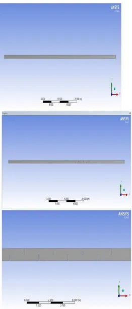
The equation of motion of Pipe with Segmented Baffles is solved using FEV tool (ANSYS-Fluent) as the equation of motion for a Pipe with Segmented Baffles is difficult to visualize therefore some FEV tool is the only solution method for analyzing hydrodynamic characteristics of Pipe with Segmented Baffles. The ANSYS 14.5 finite element program was used for analyzing Pipe flow. For this purpose, the key points were first created and then line and spline segments were formed. The lines were combined to create an area. Finally, this area was extruded a We modeled the Pipe with Segmented Baffles. The Pipe surface boundary conditions can also be provided in mesh section through naming the portion of modeled Pipe i.e Inlet, Outlet, Top wall, Bottom Wall, Baffles.
Technology (IJRASET)
A. Set preferences. (Fluid Flow (Fluent))
[image:5.612.177.439.95.706.2]B. Model the Geometry
Technology (IJRASET)
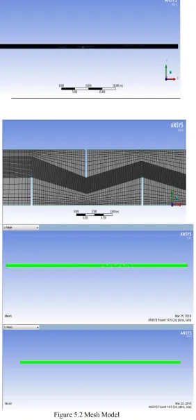
C.Generate Mesh
[image:6.612.181.463.115.720.2]D.Follow bottom up modelling and create the geometry
Technology (IJRASET)
Table 5.1 the boundary Condition for Pipe Flow [24, 34, and 15]
Working Fluid Value unit
Density, ρ 998.2 kg/m3
Viscosity, ȝ 0.001003 kg/m.s
Diameter 1 m
Specific heat, cp 4182 j/kg-k Thermal Conductivity 0.6 w/m-k
E. Give boundary condition name in mesh module such as Inlet, Outlet, Top wall, Bottom Wall, Baffles.
Figure 5.3 Boundary Condition
F.Setup, here the simulation process is begin with the giving initial condition of fluid properties and simulation starting zone.
IV. RESULTS & DISCUSSIONS
[image:7.612.178.444.229.635.2]Technology (IJRASET)
with a grid size of 106 shows good agreement during the grid dependence test. Moreover, the performance of pipe and pipe with baffles are illustrated in the corresponding results.
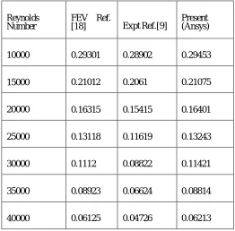
[image:8.612.175.437.168.426.2]The precision of obtained results has been validated by comparing the present result with available literature of Al- Atabi et al. [5], Muhammad [18], Jim [9] whose works are based on experimental, analytical and FVM results.
Table 6.1 Validation of Coefficient of friction with respect to varying Reynolds Number
Table 6.2 Validation of Turbulence Intensity with respect to Reynolds Number Reynolds
Number FEV Ref. [18] Expt Ref.[9] Present (Ansys)
10000 0.29301 0.28902 0.29453
15000 0.21012 0.2061 0.21075
20000 0.16315 0.15415 0.16401
25000 0.13118 0.11619 0.13243
30000 0.1112 0.08822 0.11421
35000 0.08923 0.06624 0.08814
40000 0.06125 0.04726 0.06213
Reynolds Number FEV Ref. [18] Present (Ansys)
10000 5.02512 5.05149
15000 4.80467 4.81107
20000 4.63471 4.64019
25000 4.50895 4.51219
30000 4.41011 4.41423
35000 4.32211 4.33015
[image:8.612.169.442.462.714.2]Technology (IJRASET)
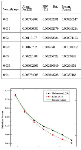
[image:9.612.168.439.93.595.2]Table 6.3 Validation of Head loss with respect to Velocity
Figure 6.1 Validation of Coefficient of friction with respect to varying Reynolds Number
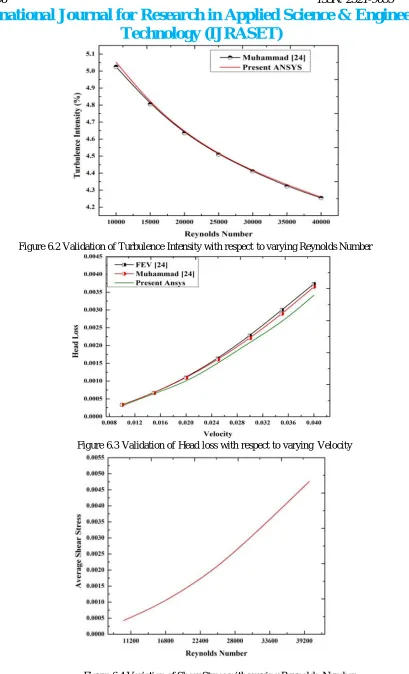
The validation of present computational work has been tabulated in table 6.1 to 6.3, and it is found that the present result shows good agreement with mentioned researchers works. The minor variation in the results is primarily due to varying operating parameters, assumptions taken during experimentation and simulation.
The small variation is results are due to variation in grid sizing, operating condition, material properties, etc. But the obtained result shows the same trend so that the results are suitably verified.
Velocity m/s Ahsan Ref.[21] FEV [21] Ref. Present (Ansys)
0.01 0.000334703 0.000332691 0.000310147
0.015 0.000666083 0.000662879 0.000649214
0.02 0.00110107 0.001088384 0.000974123
0.025 0.00163702 0.0016041 0.001501762
0.03 0.002281783 0.002206522 0.00209149
0.035 0.003002964 0.002890919 0.00264951
Technology (IJRASET)
Figure 6.2 Validation of Turbulence Intensity with respect to varying Reynolds Number
[image:10.612.105.514.34.708.2]Figure 6.3 Validation of Head loss with respect to varying Velocity
Technology (IJRASET)
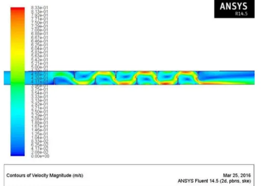
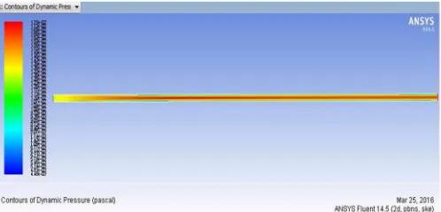
In Fig. 6.4 to 6.15 the contour plot of pipe (smooth) and pipe with baffles for various process parameters has been demonstrated. In the contour plot the fluid visualization within the pipe and pipe with baffles has been carried out and on the basis of it various result outcome i.e. Pressure drop, turbulent intensity, skin friction, shear stress has been discussed.
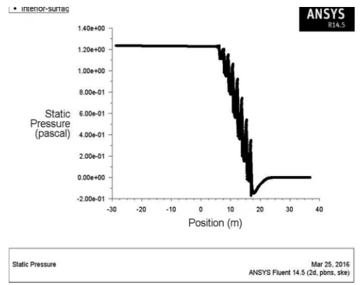
Figure 6.7 illustrates the change in pressure in the pipe and it is observed that it only occurs along the axial direction. This means that the pressure across the centre line and wall are consequently same. The static pressure continuously goes on decreasing because the is not going during this stagnation process anywhere. It is worth noting that there is an increase in the dynamic and total pressures at the pipe center relative to the walls of the pipe due to higher velocity, on the other hand again, the static pressure is constant because the flow isn't going through a stagnation process.
Because of the existence of baffles in flow the pressure drop marginally increases as Reynolds number changes. The baffles creates turbulence in the flow when mass flow rate increases, which results in an increase in a friction factor. Furthermore, agumentation in friction correspondly affects the shear stress across the wall.
Figure 6.5 Contour Plot of Velocity Magnitude of Pipe without Baffles
[image:11.612.177.441.227.413.2] [image:11.612.182.440.445.628.2]Technology (IJRASET)
[image:12.612.186.435.89.209.2]Figure 6.7 Contour Plot of Dynamic Pressure of smooth pipe
Figure 6.8 Contour Plot of Dynamic Pressure of Pipe with Baffles
Figure 6.9 Contour Plot of Pressure Coefficient of Pipe without Baffles
[image:12.612.181.438.240.358.2] [image:12.612.179.437.396.520.2] [image:12.612.171.452.548.692.2]Technology (IJRASET)
Figure 6.11 Contour Plot of Turbulence Intensity in smooth pipe
Figure 6.12 Contour Plot of Turbulence Intensity of Pipe with Baffles
[image:13.612.177.445.79.273.2] [image:13.612.170.447.310.512.2] [image:13.612.177.442.544.667.2]Technology (IJRASET)
Figure 6.14 Contour Plot of Wall Shear Stress of Pipe with Baffles
Figure 6.15 Static Pressure distributions in the pipe and pipe with baffles
Table 6.4 Effect of Reynolds number of pressure coefficient
Pressure Coefficient
Reynolds Number, Re Without Baffles Baffles
10 1.6776E-06 141.8046
100 1.6801E-05 3610.895
1000 0.00018696 275759.5
[image:14.612.179.438.239.443.2] [image:14.612.170.442.493.651.2]Technology (IJRASET)
Figure 6.16 Effect of Reynolds number on pressure coefficient
Table 6.4 and figure 6.16 shows the Effect of Reynolds number on pressure coefficient. It has been observed that pressure coefficient considerably increases linearly as Reynolds number increases. From the figure it can be more evident that the pressure coefficient for pipe with baffles is more is more remarkable.
[image:15.612.147.520.47.510.2]Technology (IJRASET)
Figure 6.17 Effect of Reynolds number on Wall Shear Stress
[image:16.612.191.415.354.686.2]The Effect of Reynolds number on Wall Shear Stress has detailed in table 6.5 and 6.17. It has examined that on increasing Reynolds number the wall shear stress increases significantly. This is because of the fact that friction factor is strong function of Reynolds number. It has also been revealed that the shear stress in pipe without baffles is 81.6% less has compared to pipe with baffles.
Table 6.6 Effect of Reynolds number on Skin Friction
Figure 6.18 Effect of Reynolds number on Skin Friction Skin Friction Coefficient
Reynolds
Number, Re Without Baffles Baffles
10 1.3011E-09 0.046251
100 1.322E-08 0.596386
Technology (IJRASET)
Table 6.6 and figure 6.18 shows the effect of Reynolds number on Skin Friction. It has seen that as Reynolds number increases skin friction increases. This is because of occurrence of turbulence in flow which results in friction. Furthermore the trend of discrepancy is same for both the pipes i.e. pipe with baffles and smooth pipe. But the baffled pipe has higher rate of friction.
[image:17.612.182.428.180.668.2]Table 6.7 Effect of Reynolds number on Pressure Drop
Figure 6.19 Effect of Reynolds number on Pressure Drop Pressure Drop
Reynolds Number, Re Without Baffles Baffles
10 2.0834E-06 3.56E-06
100 2.1646E-05 8.54E-05
1000 0.00029526 0.006368
Technology (IJRASET)
Table 6.9 and figure 6.19 shows the Effect of Reynolds number on Pressure Drop. It has examined that pressure drop raises as Reynolds number increases. This is because of rise in turbulence in the flow when pipe with baffles has used.
This is due to presence of turbulence in flow. In extinction of baffles the deviation in pressure drop in smooth pipe is 41.47% in laminar regime and 99.42% less in turbulent regime as compared with pipe with baffles.
Table 6.8 Effect of Reynolds number on Dynamic pressure
Figure 6.20 Effect of Reynolds number on Dynamic pressure 54
Table 6.8 and figure 6.20 shows the Effect of Reynolds number on Dynamic pressure. It has seen that the dynamic pressure progressively increases as the Reynolds number increases. the rate of enhancement of dynamic pressure is comparatively more in pipe with baffles. While in smooth pipe has 75.095% less dynamic pressure than pipe with baffles at high Reynolds number.
V. CONCLUSION
A. The pressure drop considerably increases on employing fragmented baffles as compared to smooth pipe.
B. On increasing Reynolds number dynamic pressure increases significantly. However, smooth pipe has comparatively low dynamic pressure as compared to baffled pipe.
C. Coefficient of skin friction increases as Reynolds number increases. In baffled pipe Coefficient of friction is significantly more due to have more surface area than smooth pipe.
D. On realizing baffles in laminar regime turbulence can be created.
Dynamic Pressure
Reynolds Number,
Re Without Baffles Baffles
10 1.5255E-08 1.9E-08
100 1.5222E-06 2.51E-06
1000 0.00014906 0.000334
[image:18.612.175.439.162.564.2]Technology (IJRASET)
E. Turbulent intensity is direct function of Reynolds number. In other words, as Reynolds number increases turbulent intensity correspondingly increases.
F. Increasing in turbulence promotes the friction factor as Reynolds number increases.
G. The thermal performance of any heat exchanger can effectively been increases by employing segmented baffles. H. Shear stress at the wall increases as the fluid flow rate increases.
I. The heat transfer characterizes in pipe and ducts are enhanced by using extended surface in form of Fin, baffles, artificial roughness which ultimately, increases the friction factor. Therefore it is extensively been employed in heat exchanger design
REFERENCES
[1] Y.S. Sun, A.F. Emery, Effects of wall conduction, internal heat sources and an internal baffle on natural convection heat transfer in a rectangular enclosure, International Journal of Heat and Mass Transfer, Volume 40, Issue 4, March 1997, Pages 915-929
[2] Kang-Hoon Ko, N.K. Anand , Use of porous baffles to enhance heat transfer in a rectangular channel, International Journal of Heat and Mass Transfer, Volume 46, Issue 22, October 2003, Pages 4191- 4199
[3] T.Y. Chiu, A.E. James, Effects of axial baffles in non-circular multi-channel ceramic membranes using organic feed, Separation and Purification Technology, Volume 51, Issue 3, October 2006, Pages 233-239
[4] K.B. Smith, M.R. Mackley, An Experimental Investigation into the Scale-up of Oscillatory Flow Mixing in Baffled Tubes, Chemical Engineering Research and Design, Volume 84, Issue 11, November 2006, Pages 1001-1011
[5] Mushtak T. Al-Atabi and S. B Chin, ―Pressure Drop in Laminar and Turbulent Flows in Circular Pipe with Baffles – An Experimental and Analytical Study‖, International Journal of Fluid Mechanics Research, Vol. 33, No. 4, 2006)
[6] Jian-Fei Zhang, Ya-Ling He, Wen-Quan Tao, 3D numerical simulation on shell-and-tube heat exchangers with middle-overlapped helical baffles and continuous baffles – Part I: Numerical model and results of whole heat exchanger with middle-overlapped helical baffles, International Journal of Heat and Mass Transfer, Volume 52, Issues 23–24, November 2009, Pages 5371-5380
[7] Seyyed M. Hasheminejad, M.M. Mohammadi, Effect of anti-slosh baffles on free liquid oscillations in partially filled horizontal circular tanks, Ocean Engineering, Volume 38, Issue 1, January 2011, Pages 49-62
[8] Wang Yongqing, , Gu Xin, Wang Ke, Dong Qiwu, Numerical Investigation of Shell-Side Characteristics of H-Shape Baffle Heat Exchanger, Procedia Engineering, Volume 18, 2011, Pages 53–58
[9] Jim McGovern, ―Technical Noteμ Friction Factor Diagrams for Pipe Flow, Dublin Institute of Technology ARROW@DIT)
[10] Changwoo Kang, Kyung-Soo Yang, Flow instability in baffled channel flow, International Journal of Heat and Fluid Flow, Volume 38, December 2012, Pages 40-49
[11] Parkpoom Sriromreun, Chinaruk Thianpong, Pongjet Promvonge, Experimental and numerical study on heat transfer enhancement in a channel with Z-shaped baffles, International Communications in Heat and Mass Transfer, Volume 39, Issue 7, August 2012, Pages 945-95
[12] J.P. Solano, R. Herrero, S. Espín, A.N. Phan, A.P. Harvey, Numerical study of the flow pattern and heat transfer enhancement in oscillatory baffled reactors with helical coil insert, Chemical Engineering Research and Design, Volume 90, Issue 6, June 2012, Pages 732-742
[13] Xin Gu, Xiao-lin Dong, Min-shan Liu and Yong- qing Wang Numerical Research on Heat Transfer and Flow Resistance Performance of Specially-Shaped Rod Baffle Heat Exchangers, Heat Transfer—Asian Research, Volume 41, Issue 1, pages 1–9, January 2012
[14] Aashique Alam Rezwan, Sarzina Hossain, S.M. Ashrafur Rahman, M.A. Islam , Heat Transfer Enhancement in an Air Process Heater Using Semi- Circular Hollow Baffles, Procedia Engineering, Volume 56, 2013, Pages 357-362
[15] Fatih Bayrak, Hakan F. Oztop, Arif Hepbasli, Energy and exergy analyses of porous baffles inserted solar air heaters for building applications, Energy and Buildings, Volume 57, February 2013, Pages 338-345
[16] Withada Jedsadaratanachai, Amnart Boonloi, Effects of blockage ratio and pitch ratio on thermal performance in a square channel with 30° double V- baffles, Case Studies in Thermal Engineering, Volume 4, November 2014, Pages 118-128
[17] Wen-xiao Chu, Ting Ma, Min Zeng, Ting Qu, Liang-bi Wang, Qiu-wang Wang, Improvements on maldistribution of a high temperature multi-channel compact heat exchanger by different inlet baffles, Energy, Volume 75, 1 October 2014, Pages 104-115
[18] Muhammad Ahsan, ―Numerical analysis of friction factor for a fully developed turbulent flow using keε turbulence model with enhanced wall treatment‖, b e n i - s u e f university journal of basic and applied sciences xxx (2014 ) 1e9)
[19] Usman Salahuddin, Muhammad Bilal, Haider Ejaz, A review of the advancements made in helical baffles used in shell and tube heat exchangers, International Communications in Heat and Mass Transfer, Volume 67, October 2015, Pages 104-108
[20] Mehdi Bahiraei, Morteza Hangi, Mahdi Saeedan, A novel application for energy efficiency improvement using nano-fluid in shell and tube heat exchanger equipped with helical baffles, Energy, Volume 93, Part 2, 15 December 2015, Pages 2229-2240
[21] A.S.M. Sayem, M.M.K. Khan, M.G. Rasul, M.T.O. Amanullah, N.M.S. Hassan, Effects of Baffles on Flow Distribution in an Electrostatic Precipitator (ESP) of a Coal Based Power Plant, Procedia Engineering, Volume 105, 2015, Pages 529-536
[22] J. Prathap Kumar andJ.C. Umavathi Free Convective Flow in an Open-Ended Vertical Porous Wavy Channel with a Perfectly Conductive Thin Baffle, Heat Transfer—Asian Research Volume 44, Issue 3, pages 227–256, May 2015
![Table 5.1 the boundary Condition for Pipe Flow [24, 34, and 15]](https://thumb-us.123doks.com/thumbv2/123dok_us/8579079.860299/7.612.178.444.229.635/table-boundary-condition-pipe-flow.webp)