International Journal of Emerging Technology and Advanced Engineering
Website: www.ijetae.com (ISSN 2250-2459, ISO 9001:2008 Certified Journal, Volume 3, Issue 8, August 2013)213
Identification of Gear Distortion in Manufacturing and Finding
Solution using Reactive Improvement Methodology
Praveeen C Gadagkar
1, Dr. D. N. Shivappa
2, Pradeepa Shivaswamy
31
P.G Student, 2Professor, Department of Mechanical Engineering, Sir M Visvesvaraya Institute of Technology, Bangalore, Karnataka Pin Code: 562 157
3Head Automotive Projects, Voith Eng. Pvt Ltd, Bangalore,Pin Code: 560046
Abstract— Voith Ltd, Bangalore is facing distortion of gears during the heat treatment. Because of this, gears are unusually given an extra machining allowance which is leading to increased production cost. In this work using the reactive improvement methodology, efforts are made to understand the problem of gear distortion and find the remedial measures. The study reveals that the many parameters affect the distortion but the most predominant is the heavy weight of the gear. In the process of analyzing the effect of gear weight on distortion problem it was identified that three parameters; (i) use of improved fixture to hold the gear during heat treatment, (ii) better cooling mechanism, and (iii) reduction of gear weight by making gear design modification can reduce the distortion. All these parameters are analyzed and discussed.
The study reveals that the reduction of gear weight with suitable gear design modification will be more effective. The gear design modification is studied further by identifying different parameters to reduce weight. It was found that by adopting stepped shaft to take away the substantial weight of the gear and providing gear ring on the stepped shaft will be most effective for reducing the distortion.
Modified setup was further studied using FE analysis for verification of distortion during the heat treatment process. The study reveals that the distortions due to heat treatment process are within the acceptable limits. After confirmation of its suitability, 'Stepped Shaft and Gear Ring' setup is adopted for the gears weighing more than 1.5 tonnes and diameter more than 1000 mm.
Keywords—Gear, FEM, Heat Treatment Process,
Distortion, Reactive Improvement Methodology.
I. INTRODUCTION
Heat-treating processes have traditionally been used to greatly enhance the mechanical properties of components made up of steel such as bearings, gears, shafts, etc. However, heat treatment processes such as carburizing, quenching and tempering often cause excessive and uncontrolled distortion. Such distortion is predominant in the components of higher weight and large dimensions.
Hence this type of distortion is a major concern in the production of high quality gears and such components. Many research groups have examined the causes of distortion and found that the thermal stresses as well as phase transformation that occur during the heat treatment play an important role in the resulting distortions. This research work considers the analysis of distortion of large gears. Distortion is a physical process and cannot be eliminated from any heat-treatment operation. All large steel gears experience distortion during the heat treatment process. Hence when the gears are hardened, distortion will eventually lower the quality level of the gears that necessitates a requirement of more time in finishing operation for higher quality. This requires higher machining allowance to be provided with teeth for finish machining before heat treatment of gears that are likely to distort.
Voith Ltd is facing the problem of distortion in the gears weighing more than 1.5 tonnes and diameter greater than 1000 mm during heat treatment process which changes the dimensions of the gear. In order to overcome this problem extra machining allowance is given to the gears. The objective of this work is to identify the root causes of distortion and find the remedial measures by using the reactive improvement methodology.
II. LITERATURE REVIEW
International Journal of Emerging Technology and Advanced Engineering
Website: www.ijetae.com (ISSN 2250-2459, ISO 9001:2008 Certified Journal, Volume 3, Issue 8, August 2013)214 In this study two approaches are considered to estimate the Heat Transfer Coefficient (HTC) for rapid cooling of the component i) Standard Heat Transfer correlations (correlated with a probe as well as with blank gear). ii) The cooling rate curve for the quenchant. Kexiu Wang Richard Pilon [4] developed two models to simulate both the heat treatment process and on-tread braking using ANSYS.A. M. S. Hamouda & C. K. Lau [5] suggested that the FEM may be employed to investigate the residual stress state and the variation of internal stresses. Shiba and others [6] suggested that there are three levels of quality management and improvement; process control, reactive improvement, and proactive improvement. Reactive improvement is a systematic process that describes, analyzes, and subsequently uncovers the root causes of the problem. It is used to solve past actions that are now causing unwanted effects.
III. PROBLEM IDENTIFICATION AND ANALYSIS
In the present work the formation of gear distortion and its remedies have been identified. It was found that gears weighing more than 1.5 tonnes are facing distortion during the heat treatment process. Because of distortion, extra machining allowance is given to gears which cause increased production cost. Hence the efforts are made to understand the problem of distortion and find the remedial measures. The reactive improvement methodology is adopted in the present study to identify the formation of gear distortion and its remedies.
A. Study of distortion problem
The gears having diameter 1250 mm and 1307 mm are having unacceptable distortion during the heat treatment process, these gears are considered for the detailed study of the distortion problem. As the study requires examining the data of gears carefully it was decided to use FE analysis approach to identify the causes of distortion. In order to carry out the FE analysis, CAD models of selected gears were developed. Brainstorming sessions were conducted to get the details of distortion problem, typical questions in the form of who, what, why, where, when and how were asked to production staff and the details are obtained through a brain storming session. This resulted in problem description which is given here under.
• Unacceptable dimensional distortion of the gear during the quenching processes.
• Post hardening dimensional distortion is at an unacceptable level, resulting in insufficient material being present in some locations such that final grinding is difficult and/or surplus material is present such that excessive grinding is necessary that reduces the hardened layer and leads to a higher likelihood of reduced performance of gears.
• Gears weighing more than 1.5 tonnes and greater than 1000mm diameter always had the problem.
[image:2.612.336.561.302.625.2]To perform FE analysis, all the necessary data such as geometry of the gear and heat treatment cycle are to be collected. Figure 1 and 2 shows the geometry of the gear and heat treatment cycle.
Figure 1: Geometry of the gear
International Journal of Emerging Technology and Advanced Engineering
Website: www.ijetae.com (ISSN 2250-2459, ISO 9001:2008 Certified Journal, Volume 3, Issue 8, August 2013)215 B. Analysis of distortion problem
A Transient (time dependent) Finite Element Analysis (FEA) is carried out for the gear subjected to a thermal load under heating and cooling cycles. Residual stresses are developed due to the heating and cooling of the component. Assuming that much of the distortion occurs during hardening process, the numerical analysis is carried out up to quenching only. A 3D sector model is chosen to reduce the computational time, yet generating the same results as that for the full 3D model. The problem is solved using transient analysis technique. The time dependent thermal loads are applied on the finite element model of the component for heating and cooling as per the heat treatment cycle. The boundary conditions in the form of constraints are then applied to the above numerical model for solving the given problem.
C. Results and Discussion
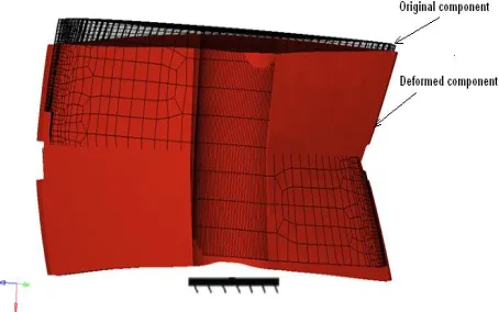
[image:3.612.316.571.158.299.2]Analysis has been carried out for three different gear configurations. Deformed shape of the component in 3D model with four critical locations is as shown in Figure 3.
Figure 3: Deformed shape of Φ1250 mm Gear
[image:3.612.53.280.386.528.2]Comparison of measured data and numerical results for three different gear configurations is provided in Table I. Distortion is measured by relating the outside diameter of the gear before and after heat treatment.
TABLE I
COMPARISON OF DISTORTION DATA AFTER HARDENING
Location of Deformation 1 2 3 4
Gear Dia 1250
mm
Actual Deformation 3.33 1.99 0.61 -0.85 Deformation Obtained
in FEA 2.15 1.36 1.04
-0.13
Gear Dia 1307
mm
Actual Deformation 3.66 1.98 1.26 -0.07 Deformation Obtained
in FEA 2.84 1.48 0.97
-0.76
Gear Dia 850
mm
Actual Deformation NA NA NA NA Deformation Obtained
in FEA 0.8 0.71 0.58 0.13
D. Outcome of distortion analysis
Problem exploration, data collection and analysis stages of Reactive improvement methodology have revealed the following important aspects of gear distortion.
• Analysis made using a reactive improvement methodology gives a clear view of the gear distortion. • The observed nature of distortion and the values from
the numerical analysis is in agreement with the nature of measured distortion and the values of the actual gears.
• The study reveals that the parameters mentioned below affect the gear distortion.
a) Higher temperature of 900 oC.
b) Longer heating time of close to 35 hours. c) Creep behavior at that time and temperature. d) The heavy weight of the gears.
• To achieve required hardness on the gears, the time and temperature parameters cannot be modified. While the creep effect is the part of material behavior and it cannot be changed. To overcome the gear distortion problem, the focus was made to analyze the effect of gear weight.
International Journal of Emerging Technology and Advanced Engineering
Website: www.ijetae.com (ISSN 2250-2459, ISO 9001:2008 Certified Journal, Volume 3, Issue 8, August 2013)216
IV. REMEDIAL MEASURES FOR DISTORTION
Thorough analysis of distortion problem was made and it was identified that there are three alternative solutions such as; (1) Improved fixture, (2) Cooling mechanism, and (3) Gear design modification which can be considered to overcome the distortion problem. These three alternative solutions were further analyzed for their suitability which is explained in the following sections.
1) Use of Improved Fixture during Heat Treatment:
Presently, three point fixture is used to support the gear during the heat treatment process. Due to self-weight of the gear it gets sagged during the heat treatment process. The reason may be due to the inadequate support provided for the gear during heat treatment. Therefore to provide better/adequate support to gear to avoid sagging during the heat treatment process following methods can be employed; a) Four Point Fixture, b) Flat cylindrical plate. It is considered that improving fixture during the heat treatment process is not the ideal remedial measure for the current gear distortion problem. So it is not considered for further application.
2) Better Cooling Mechanism:
Better cooling mechanism may be considered to reduce the gear distortion which is necessary during quenching to allow optimum heat extraction from the component. There are three methods for better cooling during quenching which are; a) Drilling holes, b) Marquenching oils and c) Agitation rate. It is considered that better cooling mechanism may not completely eliminate distortion hence this method also not considered.
3) Gear Design Modification:
In the third solution, complete modification of the gear is considered. Gear design modification is done to reduce the weight of the gear in such a way that the design is acceptable, manufacturable, cost and time should remain same or reduced. For the gear design modification, three parameters are considered, that are; a) Gear thickness, b) Drilling holes within the gear component and c) Stepped shaft and gear ring.
The gear weight can be reduced effectively by increasing the shaft diameter. But increase in shaft diameter leads to change the design of the interconnected elements. This adds to the complexity and economic burden. Therefore, instead of increasing diameter of the shaft throughout, a stepped shaft (i.e. diameter of shaft is increased at the place where gear is mounted) is used.
Since the use of the stepped shaft does not pose any problems to the interconnected elements, this solution found to be more appropriate and economical method of reducing the gear weight.
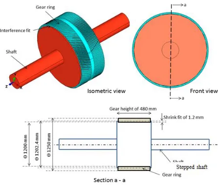
Gear design modification is done by increasing the diameter of the shaft. Since the shaft diameter is more modified so the gear is known as gear ring. The gear ring are easy to manufacture and acceptable in all levels (manufacturing, cost and performance). Thus by introducing gear ring, the time required to perform heat treatment process also get reduced drastically. The assembly of the stepped shaft and gear ring design is as shown in Figure 4.
Figure 4: D/t views and dimensional details for the Assembly of Gear Ring and Shaft
A. Analysis of gear ring
A FE Analysis is carried out for the gear ring subjected to a thermal load under heating and cooling cycles. Distortion of the component is measured at the end of quenching process. The time dependent thermal loads are applied to the Finite Element model of the component for heating and cooling as per the heat treatment cycle. The heat treatment cycle for FE analysis of gear ring is as shown in Figure 5.
B. Results of implementation
[image:4.612.331.554.296.486.2]International Journal of Emerging Technology and Advanced Engineering
Website: www.ijetae.com (ISSN 2250-2459, ISO 9001:2008 Certified Journal, Volume 3, Issue 8, August 2013)217
Figure 5: Heat Treatment Chart for Analysis of Gear Ring
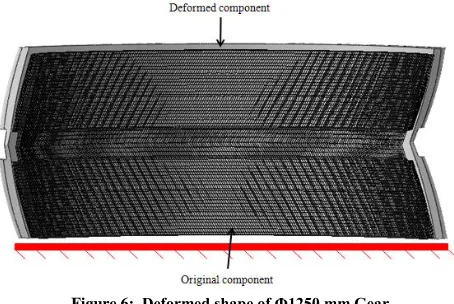
[image:5.612.47.277.141.283.2]Thus, the HTC obtained from numerical calculations helps in predicting the surface temperature of the component during the quenching process. The deformed shape of the component is shown in Figure 6.
Figure 6: Deformed shape of Φ1250 mm Gear
Comparison of measured data and numerical results for three different gear configurations is provided in the following Table II. Distortion is measured by relating the outside diameter of the gear before and after heat treatment.
TABLE II
COMPARISON OF DISTORTION DATA AFTER HARDENING
Location of deformation 1 2 3 4
Gear Dia 1250 mm
Actual deformation 0.80 0.59 0.59 0.81
Deformation obtained in
FEA 0.79 0.58 0.57 0.79
Gear Dia 1307 mm
Actual deformation 0.92 0.78 0.78 0.92
Deformation obtained in
FEA 0.85 0.71 0.7 0.81
Gear Dia 850 mm
Actual deformation NA NA NA NA
Deformation obtained in
FEA 0.42 0.34 0.34 0.42
V. CONCLUSION
Following conclusions are made from the research work on solving the gear distortion problem.
• Analysis made using reactive improvement methodology provided gives a clear view of the gear distortion.
• The numerical analysis provides an insight into the physical behaviour of the gear during carburizing, re-heating and quenching processes.
• The observed nature of distortion for different gears from the FE analysis is in agreement with nature of the measured distortion of the actual gears. The numerical values of distortion are also found to be in reasonable agreement with measured data, with any differences attributable to the assumptions made in the analysis.
• The study reveals that the parameters mentioned below affect the gear distortion.
a)Higher temperature of 900 oC. b)Heating time of close to 35 hours.
c)Creep behaviour at that time and temperature. d)The heavy weight of the gears.
• To achieve the required hardness on the heavy gears, the time and temperature parameters cannot be modified as the creep effect is the part of material behaviour and it cannot be changed.
• To overcome the gear distortion problem the focus was made to analyze the effect of gear weight. • By introducing the gear ring for diameter greater than
1000 mm, the gear distortion problem is reduced drastically without increasing the manufacturing cost and time.
• The time for heat treatment of gear ring is reduced by 65%.
Acknowledgement
We take this opportunity to give a sincere gratitude to Voith Engineering Service Pvt Ltd, for giving an opportunity to carry out the work.
REFERENCES
[1] J.R. Davis, Davis & Associates, “Gear materials, properties, and manufacture”, pp 89-90, Sept 2005.
[2] Prof. K.Gopinath & Prof. M.M.Mayuram, “Gear manufacturing”, pp 2-25, Dec 2001.
[3] S. Shiba, A. Graham, D. Walden, “A new American TQM, Productivity Press, Portland, Or”, 1993.
[image:5.612.53.280.359.511.2]International Journal of Emerging Technology and Advanced Engineering
Website: www.ijetae.com (ISSN 2250-2459, ISO 9001:2008 Certified Journal, Volume 3, Issue 8, August 2013)218
[5] Abaqus documentation, “Creep formulation and coefficients”, Version 6.7.
[6] Prof. M. Zenouzi, “Transient Response Characteristics and Lumped System Analysis of Geometrically Similar Objects”, Oct2009. [7] S. Timoshenko, “Strength of Materials”, II Edition.
[8] Kexiu Wang & Richard Pilon, “Investigation Of Heat Treating Of Railroad Wheels And Its Effect On Braking Using Finite Element Analysis”, pp 2-25, Dec 2001.