International Journal of Emerging Technology and Advanced Engineering
Website: www.ijetae.com (ISSN 2250-2459,ISO 9001:2008 Certified Journal, Volume 4, Issue 6, June 2014)
916
Design Optimization and Analysis of Pipe Holding Structure
Used in Underground Miner
Kalamadhu M T
1, Punith Gowda K
2, Dr. Maruthi B H
3, Manohar
41
PG Scholar, 2Asst. Professor, 3Professor and Head, Dept. of Mech. Engg. EWIT, Bangalore
4Technical Consultant, EMC Projects, Bangalore.
Abstract— The main aim of any design process involves
optimization of the structure, keeping in mind that the strength, manufacturability and cost involved in producing such a structure. This project aims at designing pipe holder structure to hold certain number of pipes of standard sizes and analyzed for the available mounting options. The design also involves fixing the bolts number and size used to mount the structure at the finalized mounting point.
The material selection process also obtains the reaction load which is described to achieve a better understanding of the mesh type, mesh size and boundary conditions applied to complete an effective FEA model. At last the design objective could be simply, to minimize cost of the structure by reducing material and improving the structural strength.
The results obtained from FEA analysis and numerical calculation values are validated to check the accuracy of the results.
Keywords-- FEAMODEL,PIPE HOLDER,ANSYS,MESHING, CATIA,MINING,
I. INTRODUCTION
Underground mining is done when the rocks, minerals, or gemstones are too far underground to get out with surface mining. Some kinds of underground mining are:
a) Borehole Mining b) Drift Mining c) Hard Rock Mining d) Shaft Mining e) Slope Mining [1-3]
In order for the minerals to be taken out of the mine, the miners make underground rooms to work in. The mining company chooses the best way to get the minerals out. Most mining is done using Continuous mining that uses a continuous mining machine to cut coal from the walls. This means there is less blasting and drilling and puts less miners down in the mines.
Mineral production in which all extracting operations are conducted beneath the ground surface is termed underground mining. Underground mining methods are usually employed when the depth of the deposit and/or the waste to ore ratio (stripping ratio) are too great to commence a surface operation.
Once the economic feasibility has been verified, the most appropriate mining methods must be selected according to the natural/geological conditions and spatial/geometric characteristics of mineral deposits. Considerations include:
a)Spatial/geometric characteristics of the deposit concerned: the shape, size, thickness, plunge, and depth.
b) Strength of the hanging wall, footwall, and ore body. c)Economic value of the ore and grade distribution
within the deposit.
The selection of underground mining methods is primarily based on the geological/spatial setting of the deposit. Candidate methods can therefore be chosen and ranked based on estimated operational/capital costs, production rates, availability of labors and materials/equipment’s, and environmental considerations. The method offering the most reasonable and optimized combination of safety, economics, and mining recovery is then chosen. [4]
Reflecting the importance of ground support, underground mining methods are categorized in three classes on the basis of the extent of support required: unsupported, supported, and caving.
Supported methods require substantial amounts of artificial support to maintain stability in exploitation openings, as well as systematic ground control throughout the mine.
International Journal of Emerging Technology and Advanced Engineering
Website: www.ijetae.com (ISSN 2250-2459,ISO 9001:2008 Certified Journal, Volume 4, Issue 6, June 2014)
917 The most satisfactory forms of artificial support are backfilling/stowing, timbers, cribs/packs, and hydraulic/frictional props. There are three specific methods in the supported class.
a) Cut-and-fill stopping b) Stull stopping c) Square-set stopping
Cut-and-fill and still stopping are intended for moderately competent rock, whereas square-set stopping is suitable for the least competent rock. Supported methods have declined in use since World War II, primarily because cut-and-fill stopping is the only method that lends itself to mechanization. Stull stopping and square-set stopping are infrequently used and relatively unimportant today, because of excessive labor intensity and very low productivity, in addition to a scarcity of skilled work forces and available timber resources. Only cut-and-fill stopping will be described later in detail. [4 - 13]
The main objective of this project is to optimize the structure, keeping in mind the strength, manufacturability and cost involved in producing such a structure. In this project the pipe holder is designed to hold certain number of pipes of standard sizes, the holder is analyzed for the available mounting options and the best option is chosen for manufacturing. The design involves fixing the bolts number and size used to mount the structure at the finalized mounting point.
FEA has been used to analyses the stresses and displacements of the part and also to find the reaction forces. The FEA model is described to achieve a better understanding of the mesh type, mesh size and boundary conditions applied to complete an effective FEA model. At last the design objective could be simply to minimize cost of the structure by reducing material and improving the structures strength. The reactions obtained from Ansys and hand calculated is compared to check the accuracy of results.
II. METHODOLOGY
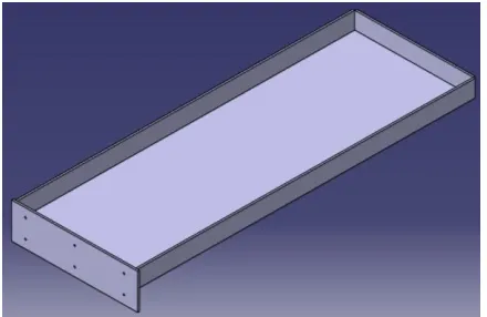
This work begins with the modeling of the pipe holding structure. This is done by using CATIA software. The CATIA model is then meshed using the SHELL63 and BEAM188 elements using the Hypermesh software. The meshing is done surface by surface and then assembled for analysis. Some of the edges are meshed using a mixture of quad and tria elements.
The meshed model is finally used for the analysis for four mounting cases using ANSYS 14.1 software. The detailed description of the elements used have been given in the ensuing paragraphs.
FEA Elements used:
SHELL63 Element Description
SHELL63 has both bending and membrane capabilities. Both in-plane and normal loads are permitted. The element has six degrees of freedom at each node: translations in the nodal x, y, and z directions and rotations about the nodal x, y, and z-axes. Stress stiffening and large deflection capabilities are included. A consistent tangent stiffness matrix option is available for use in large deflection (finite rotation) analyses. Similar elements are SHELL43 and SHELL181 (plastic capability), and SHELL93.
BEAM188 Element Description
BEAM188 has six or seven degrees of freedom at each node, with the number of degrees of freedom depending on the value of KEYOPT (1). When KEYOPT (1) = 0 (the default), six degrees of freedom occur at each node. These include translations in the x, y, and z directions and rotations about the x, y, and z directions. When KEYOPT (1) = 1, a seventh degree of freedom (warping magnitude) is also considered. This element is well-suited for linear, large rotation, and/or large strain nonlinear applications.
III. CASE STUDY
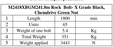
[image:2.612.333.555.543.635.2]In the present work, the pipe holding structure has been analyzed for four cases. The materials used and calculations have been detailed below. Table 1 lists the specifications of the bolts and nuts used in the study.
Table 1
Bolt & Nut Input Specification
M2418XBGM241.8m Rock Bolt- X Grade Black, Chemdrive Green Nut
1 Length 1800 mm
2 Units 65
3 Weight of one bolt 5.4 Kg
4 Total Weight 351 Kg
International Journal of Emerging Technology and Advanced Engineering
Website: www.ijetae.com (ISSN 2250-2459,ISO 9001:2008 Certified Journal, Volume 4, Issue 6, June 2014)
918 Case1: CAD model of simply supported overhanging beam with one end fixed.
Case 2: CAD model of Cantilever beam with one end fixed.
Case 3: CAD model of simply supported over hanging structure.
Case 4: CAD model of the structure with both ends fixed.
IV. ANALYSIS
The analysis is carried out by using both hand calculations and by using FEM methods (ANSYS). The obtained hand calculation results are cross checked with the results obtained by using ANSYS. As previous told this paragraph incorporates the analysis of the pipe holding structure for four different cases.
[image:3.612.59.279.163.306.2]Case 1:Simply supported over hanging beam with one side fixed.
Fig. 1: Line diagram for Case 1 analysis To find values of MA and RA from figure (1)
RA + RB = 3443.3 + 0.07 (1800) = 3569.3N
Substituting value of RB we get
RA =3569.3–2004.34= 1564.96N
MA = (3443.3*978) + (0.07*1800*1800/2) - (2004.3*1400)
=3367547.4 +113400–2806020 MA = 674927.4N-mm
Shearing force values:
Shearing force just to the right of RB= 0.07(1800 - 1400) =
28 N
Shearing force just to the left of RB= 28-2004.34 =-1976.34
N
International Journal of Emerging Technology and Advanced Engineering
Website: www.ijetae.com (ISSN 2250-2459,ISO 9001:2008 Certified Journal, Volume 4, Issue 6, June 2014)
919 Shearing force just to the left of F =-1946.8+3443.3 = 1496.5 N
Shearing force just to the right of RA= 1496.5+ (0.07*978)
=156
Bending moment values:
Bending moment at reaction RB = 0.07 * (1800 -1400) *
(1800-1400) / 2 = 5600N
Bending moment at load F = 0.07 * (1800 -978) * (1800 - 978) / 2 - 2004.34 * (1400-978)
= 23648.94-845831.48 = -822182.54N
Bending moment at reaction RA = (0.07*1800) +
[image:4.612.50.565.106.681.2](3443.3*978) – (2004.34*1400) = 561636.52N
Fig 2 : Shear force distribution of case1
Fig 3: Bending moment distribution of case1
[image:4.612.332.551.156.217.2]Case 2: Cantilever beam with one end fixed.
Fig. 4: Line diagram for Case 2 analysis RA = 3443.34+ (0.07*1800) =3569.3N
MA = (3443.34*978) + (0.07*1800*1800/2)
=3480947.4N-mm
Shear force values:
Shear force just to the right of C = 0.07*(1800-978)= 57.54N
Shear force to the left of C = 57.54+3443.34=3500.88N Shear force to the right of A = (0.07*1800)+3443.3= 3569.3N
Bending moment values:
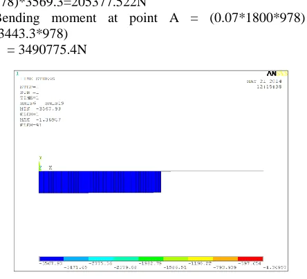
Bending moment at point C = 0.07*(1800-978)*3569.3=205377.522N
Bending moment at point A = (0.07*1800*978) + (3443.3*978)
= 3490775.4N
[image:4.612.57.278.255.628.2] [image:4.612.329.551.385.587.2]International Journal of Emerging Technology and Advanced Engineering
Website: www.ijetae.com (ISSN 2250-2459,ISO 9001:2008 Certified Journal, Volume 4, Issue 6, June 2014)
[image:5.612.330.538.134.315.2]920 Fig 6: Bending moment distribution of case2
Case 3: Simply supported over hanging beam
Fig. 7: Line diagram for Case 3 analysis RA + RB = 3443.34 + (0.07*1800) = 3569.3N
∑MA = 0
RB * 1400 = (3443.34*925) + (0.07*1800*1800/2)
RB = 2680N; RA = 889.3N
Shear force diagram
Shear force to the right of B = 0.07(1800-1400) =28N Shear force to the left of B = 28-2680=-2652N
Shear force to the right of C = 0.07*(1800-925)-2680=-2618.75N
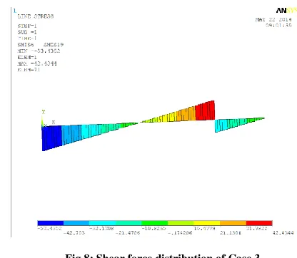
Shear force to the left of C= -2618+3443.3=825.3N Shear force to the right of A = (0.07*1800) + 3443.3-2680 = 889.3N
Fig 8: Shear force distribution of Case 3
Case 4: Both ends fixed beam
Shear force values:
Shear force to right of A=1712.9 N
Shear force to left of A=1712.9 - (0.07 * 925 * 925 / 2) = - 28233.97N
Shear force to right of B=1712.9 -(0.07 * 925 * 925 / 2) + 344 = - 24790.675N
Shear force to left of B = - 1856.4 N
Bending moment values:
Bending moment at A=-771540.68N-mm Bending moment at below load
[image:5.612.64.271.135.307.2]=-771540.68 + (0.07*925*925/2) =-741593.805N-mm
[image:5.612.336.538.480.680.2]International Journal of Emerging Technology and Advanced Engineering
Website: www.ijetae.com (ISSN 2250-2459,ISO 9001:2008 Certified Journal, Volume 4, Issue 6, June 2014)
[image:6.612.54.273.401.557.2]921 Fig 10: Bending moment distribution of Case 4
V. FEAANALYSIS
Pipe holder structure is analysed numerically for four available mounting options:
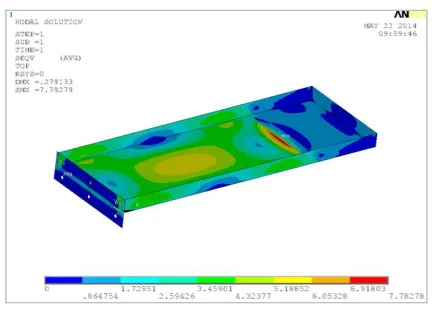
Stress and deflection plots Case 1
Maximum stress obtained= 7.78278Mpa
Maximum deflection obtained = 0.278133 mm
Stress and deflection plots Case 2
Maximum stress obtained= 91.206 Mpa
International Journal of Emerging Technology and Advanced Engineering
Website: www.ijetae.com (ISSN 2250-2459,ISO 9001:2008 Certified Journal, Volume 4, Issue 6, June 2014)
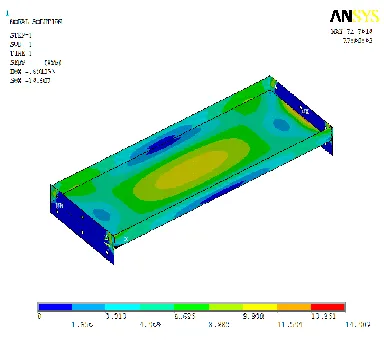
922 Stress and deflection plots Case 3
Maximum stress obtained= 17.4505 Mpa
Maximum deflection obtained = 0.940498 mm
Stress and deflection plots Case 3
Maximum stress obtained= 14.907 Mpa
Maximum deflection obtained= 0.691353 mm
[image:7.612.62.254.523.693.2]VI. RESULTS &CONCLUSION
Table 2
List of reaction force and moment reactions
Loa d case
Force Reactions(N) Moment Reactions
Analytical Ansys Analytical Ansys
1 Ra= 1564.9
Ra= 1563.2
Ma = 674927.4
Ma = 672670
2
Ra=3569. 3 Rb=2004. 3
Ra=3569. 3 Rb=2006. 3
Ma=3480947.
4 Ma=34812
3 Ra=2680 Rb=889.3
Ra=2689 Rb=880.3
4
Ra=1712. 9 Rb=1856. 4
Ra=1732. 5 Rb=1836. 8
Ma =771540.7 Mb=814548.7
Ma=777630 Mb=808730
It can be observed from the Table 2 that the Force and Moment reactions are in acceptable range. The maximum deviation for Force reaction can be observed for Reaction RA of 1.14% in Load case 4 (Both ends fixed). Similarly
for the Moment reaction it can be found in Moment MA of
International Journal of Emerging Technology and Advanced Engineering
Website: www.ijetae.com (ISSN 2250-2459,ISO 9001:2008 Certified Journal, Volume 4, Issue 6, June 2014)
923 Stress plots show that the Structure is subjected to a maximum stress of 73 Mpa in Load case 2 which is safe for ASTM A36 material.
REFERENCES
[1] http://www.chacha.com/question/what-are-underground-mines-made-of-and-how-do-they-work (accessed on: 18-06-2014) [2] http://miningyouth.blogspot.com/2009/12/underground-mining.html
(accessed on: 18-06-2014)
[3] http://www.coalsurfacemining.com/mining/used-underground-mining-equipment.html (accessed on: 18-06-2014)
[4] Underground mining methods and equipment by S Okubo and J Yamatomi, University of Tokyo, Japan, http://www.eolss.net/sample-chapters/c05/e6-37-06-02.pdf (accessed on: 18-06-2014)
[5] http://library.thinkquest.org/05aug/00461/machinery.htm#undergrou nd (accessed on 09-03-2014)
[6] Hartman H.L. ed.(1992). Mining Engineering Handbook, 2nd Ed. 2170 pp., Society for Mining, Metallurgy, and Exploration, Inc. (Littleton, USA).
[7] Hustrulid W.A. ed. (1982). Underground Mining Methods Handbook, 1754 pp., Society for Mining, Metallurgy, and Exploration, Inc. (Littleton, USA).
[8] Peng S.S. (1978). Coal Mine Ground Control, 450 pp., John Wiley & Sons, Inc. (New York, USA). [A comprehensive textbook on roof control of underground coal mine openings]
[9] Stack B. (1980). Handbook of Mining and Tunneling Machinery, 742 pp., John Wiley & Sons, Inc. (New York, USA).
[10] Stout K.S. ed. (1980). Mining Methods & Equipment, 217 pp., McGraw-Hill, Inc. (New York, USA).
[11] http://www.wisegeek.com/what-is-a-rock-bolt.htm (accessed on 20-05-2014)
[12] http://www.minova.com.au/assets/M24-Rock-Bolts-PDS-31.8.11.pdf (accessed on 20-05-2014)