VOLUME ONE
SPECIFICATIONS AND BASIC OPERATION MANUAL
02114-90398
MODEL 21148
COMPUTER
HEWLETT-PACKARD COMPANY
TABLE OF CONTENTS
Section Page
I
II
III
DOCUMENTATION DESCRIPTION
1-1. Basic Computer Manuals . . 1-1 1-3. Specifications and Basic
Opera-tion Manual . . . 1-1 1-5.
1-7.
1-11. 1-13.
Installation and Maintenance Manual . . . . Input/Output System Operation
Manual . . . . Programmer Reference Manuals System Supplement . . . .
HP 2114B SPECIFICATIONS
2-1. Definition of Computer System 2-5. Physical Specifications
2-12. Machine Timing . . 2-20. Memory.. 2-21. Type . . . 2-23. Layout. . 2-25. Addressing 2-30. Working Registers . 2-39. Panel Controls . . . 2-50. Protected Controls 2-53. Instructions.... 2-55. Formats . . .
2-60. Memory Reference Instructions 2-78. Register Reference Instructions . 2-83. Input/Output Instructions 2-105. Data Formats . . . . 2-107. Input/Output Specifications 2-108. Input/Output System Design 2-113. Interrupt Structure . . 2-122. Processor Options . . . . 2-129. Input/Output Options 2-138. Software . . . . 2-139. General . . . . 2-143. Basic Control System 2-148. Symbolic Editor 2-150. Assembler.. 2-153. FORTRAN 2-156. ALGOL.. 2-159. BASIC
2-162. Hardware Diagnostics
1-1 1-2 1-2 1-2 2-1 2-1 2-2 2-3 2-3 2-3 2-3 2-4 2-4 2-5 2-5 2-6 2-6 2-7 · . 2-10 · . 2-11 · . 2-11 2-11 · . 2-13 . 2-15 . 2-15 · . 2-16 · . 2-16 2-16 · . 2-18 · . 2-18 2-18 · . 2-18 2-18 · . 2-19
FUNDAMENTALS OF COMPUTER OPERATION 3-1. Introduction.... . . 3-1 3-5. Front Panel Presentation . . . . . . 3-1
Section 3-15. 3-23. 3-40. 3-42. 3-50. 3-59. 3-63. 3-69. 3-77. 3-80. 3-104. 3-107. 3-119. 3-133. 3-150. Number Conversions Arithmetic Operations Computer Structure
The Memory Module The Registers . . . . . The Bus System . . . . The Instruction Logic . The Input/Output System Implementation of Instructions .
Memory Reference . . . . Register Reference . . . Shift-Rotate Instructions Alter-Skip Instructions . . Input/Output Instructions Interrupt Phase . . . .
Page 3-3 3-4 3-6 3-6 3-8 · . 3-10 · . 3-10 . . . 3-11 3-12 3-13 3-19 3-19 · . 3-21 3-21 3-22
IV BASIC OPERATION OF HP 2114B COMPUTER
4-1. Introduction... 4-1
4-4. Coding... 4-1
4-8. Computer Turn-On . . . 4-2 4-11. Preliminary Operations 4-2 4-14. Manual Storing . . . 4-2 4-18. Programmed Storing 4-2 4-22. The Stored Program 4-3
4-26. Program Table 4-3
4-31. Program Execution . . ' 4-6 4-44. Referencing Other Pages 4-9 4-47. Concept of the Memory Page 4-9 4-52. Direct References . . . 4-10 4-55. Indirect References . . 4-10 4-57. Program Example . . 4-10 4-63. Jumps... . . 4-12 4-73. Introduction to Program Development. 4-13 4-78. Looping and Counting . . 4-13 4-79. The Program Loop . . 4-13 4-83_ Counting to a Limit . . . . 4-14 4-87. Tallying . . . 4-14 4-89. Initialization. . . 4-15 4-93. Complete Program . . 4-15 4-100. Special Addressing Methods . 4-16 4-104. Address Modification . . . 4-16 4-110. Addressing the Accumulators . . 4-19 4-116. Introduction to Flowcharting . . 4-19 4-133. Summary . . . 4-22
APPENDIX A REFERENCE TABLES . . . A-1
LIST OF ILLUSTRATIONS
Figure Title Page
1-1. Basic HP 2114B Computer 1-0 1-2. HP 2114B System Documentation 1-1 2-1. HP 2114B Computer Dimensions
..
2-2Figure Title
2-2. Machine Timing
2-3. Basic Instruction Formats . . . 2-4. Memory Reference Instructions . .
Page
Figure 2-5. 2-6. 2-7. 2-8. 2-9. 2-10. 2-11. 3-1. 3-2. 3-3. 3-4. 3-5. 3·6. 3-7. 3·8. 3-9. 3·10. Table 2-1. 2-2. 2-3. 3-1. 4-1. 4-2. 4-3. 4-4. 4-5. 4-6.
LIST OF ILLUSTRATIONS (CONTINUED)
Title
Shift-Rotate Instructions Alter-Skip Instructions Input/Output Instructions Basic Data Format
Input/Output Design Arrangement Components of Typical Input/Output
Interface Cards. . . . Input/Output Option Locations
(Top View) . . . . HP 2114B Computer Simplified
Block Diagram . . . . Composition of Octal Digits Binary /Octal Conversions . .
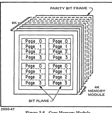
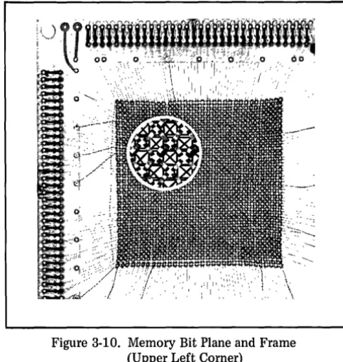
Significance of Digits in Three Systems Memory Block Diagram . . . . Core Memory Module . . . . Binary Storage in a Magnetic Core Core Addressing, Reading, and Writing Memory Cell Selection . . . . Memory Bit Plane and Frame (Upper Left
Page
2·9 2·9 2-10 . . 2-11 · 2-12
2-13 2-15 3-1 3·2 3-2 3-3 3-6 3-7 3-7 3-7 3-8
Corner) . . . . 3-8
LIST OF
Title Page
Logic Truth Table . . . 2-7 Select Code Assignments 2-13 Standard HP Software · 2-17 Shift Rotate Functions 3-20
Program Table
...
4·6Program to Show Instruction, Data, and
Address Words
.
.
. .
.
. .
.
. .
.
4-7 Single Cycle Execution of a Program 4-8 Memory Pages . . . 4-9 Program for Interpage Referencing · 4-11 Examples of Program Jumps. .
.
· 4-12Figure 3-11. 3-12. 3-13. 3-14 . 3-15. 3-16. 3-17. 3-18. 3-19. 4-1. 4-2. 4-3. 4-4. 4·5. 4·6. 4-7.
Title Page
Register Block Diagram . . . . Bus System Block Diagram . . . . Instruction Logic Block Diagram Input/Output System Block Diagram Implementing Memory Reference
3-9 3-11 3-11 · . 3-12
Instructions . . . . Implementing Register Reference
Instructions . . . . Implementing Input/Output Instructions Register Manipulations for Indirect Jump . Register Manipulations for Indirect "And" Coding a Memory Reference Instruction
Word . . . . Two Methods of Storing Information in
Memory . . . . Storing Information Manually . . . . . Storing Information by Program . . . . Direct and Indirect References to Other
Pages . . . . Examples of Interpage Referencing I . • • •
Flowchart for Shift-Rotate Demonstration 3-14
· 3-15 3-16 · 3-17 · 3-18
4-1 4-3 4-4 4-5 4-10 4-11 4-20
TABLES
Table Title Page
4-7. Preliminary Program Development . . . 4-16 4-8. Program to Illustrate Looping and
Counting
. ...
4-17 4-9. Program to Illustrate Special AddressingMethods . . . · . 4-18 4-10. Program to Demonstrate Shifts and
HP 2114B COMPUTER
IN01tx
DOCUMENTATION
AC LINE CORD
EXTENDER CARD
2038-1
)
SECTION I
DOCUM ENTATION DEseR IPTION
1-1. BASIC COMPUTER MANUALS.
1-2. Documentation supplied with the Hewlett-Packard 2114B Computer consists of four manuals, the contents of which are described briefly in paragraphs 1-3 through 1-12. When the basic HP 2114B Computer (figure 1-1) is pur-chased as part of a computer system, the system documen-tation will include a system supplement (paragraph 1-13) containing individual manuals for the peripheral equipment. Figure 1-2 illustrates the organization of the documentation supplied with a typical system.
1-3. SPECIFICATIONS AND BASIC OPERATION MANUAL.
1-4. Volume one is the specifications and basic opera-tion manual, which describes the basic HP 2114B Com-puter, treated as an independent instrument operable from the front panel. Separate sections of this manual introduce the computer from the following standpoints:
a. Specifications: The full capabilities of the HP 2114B Computer are defined, including standard hardware options and standard software. Information necessary for coding machine-language instructions is listed and described. This section is intended both as a reference for users who are familiar with computer terminology and as a source of detailed definitions, so that the material will be meaningful to readers at a wide range of levels.
b. Fundamentals of Computer Operation: For users with little or no previous experience with computers, this section gives a brief outline of how the computer works internally. This is not a detailed theory of operation, such as is presented in volume two (installation and mainte-nance) but the logic descriptions in volume two will assume at least this basic level of understanding. Thus a thorough reading of this section is advised before proceeding to the installation and maintenance manual.
c. Basic Operation of HP 2114B Computer: This is a continuation of the preceding section. Procedures for first-time usage are detailed, using the computer front-panel controls and indicators as an elementary input/output device. This section is essentially an introduction to machine-language programming. The assembler and other programming reference manuals included in volume four assume a basic knowledge of machine-language program-ming, such as presented in this section.
1-5. INSTALLATION MANUAL.
AND MAINTENANCE
1-6. Volume two gives instructions for installation and maintenance of the main unit only (see volume three for
VOLUMES ONE AND TWO
SPECIFICATIONS AND BASIC OPERATION
INSTALLATION AND MAINTENANCE
VOLUME THREE
MANUAL SUPPLEMENTS
INPUT/OUTPUT SYSTEM OPERATION
HARDWARE SYSTEM INSTALLATION RECORD
BASIC VOLUME 3 TEXT
VOLUME FOUR
PROGRAMMER'S REFERENCE MANUALS
LIBRARY 130UTINE MANUALS
UTILITY ROUTINE MANUALS
HP 2114B SOFTWARE MANUAL SUPPLEMENTS
SYSTEM SUPPLEMENT
2038-2
~
} PERIPHERAL DEVICE~ MANUALSUPPLEMEN~
~
PERIPHERAL DEVICEMANUALS
Figure 1-2. HP 2114B System Documentation
interconnection and installation of peripheral equipment). Contents of this volume are as follows:
a. General Information. This section contains a general description of the computer. Included are descriptions of the purpose and contents of the manual and a general description of the computer. Descriptions of the various computer assemblies, panel controls, and maintenance
features, and a list of required test equipment are also included.
b. Installation. This section contains procedures for installation and preparation of the unit for use. Topics covered include inspection, inventory, and performance checkout.
c. Theory of Operation. This section contains a description of the overall operation of the computer and detailed descriptions of the various operational sections of the computer. Reference is made to the logic diagrams in the maintenance section and block diagrams and waveforms in the troubleshooting section.
d. Troubleshooting. This section contains trouble-shooting procedures for the computer. Included are pretest instructions, diagnostic interpretation information, logic equations, and timing diagrams. Procedures for running the diagnostic tests are contained in the Manual of Diagnostics. Detailed procedures for troubleshooting specific opera-tional sections of the computer such as the central proces-sory, memory, and power supply are also given in this section.
e. Maintenance. This section contains preventive and corrective maintenance information for the computer. Included in this section are adjustment and test procedures, a signal index, interconnection and wiring information, and schematic and parts location diagrams. Also included are tables of replaceable parts in order of reference designations for each computer assembly.
f. Replaceable Parts. This section contains informa-tion for ordering replacement parts for the computer. All replaceable parts are listed in order of the HP part number. The total quantity of each part used, a description of the part, the manufacturer, and the manufacturer's part number are also included in this section.
g. Appendixes. Appendixes containing explanations of the logic symbology used in the manual, operating charac-teristics for the logic circuitry and backdating information for the manual are included following the last section of the manual.
1-7. INPUT/OUTPUT SYSTEM OPERATION MANUAL.
1-8. Volume three describes the input/output structure and provides theory of operation for the I/O control card. Included are sections describing the operation of the inter-rupt and priority systems as well as the encoding and decoding of interrupt requests and select code addresses.
1-9. Sections for input/output options are inserted as required, according to the interface kits purchased as part of a particular system. The information in these sections condenses operating procedures from the manuals of the individual instruments, and adds material relating specifi-cally to operation with the HP 2114B Compu~er. Mainte-nance information in these sections covers only the inter-face circuits, and not the peripheral itself. Complete operating and service manuals for the peripheral equipment are furnished in the system supplement when included in a particular system. Manual supplements describing produc-tion changes affecting volume three are included in the volume three binder.
1-2
1-10. A Hardware System Installation Record at the front of the system supplement defines the system config-uration as originally shipped, and provides an index to the supporting documents in the system supplement. Space is provided for noting changes and additions.
1-11. PROGRAMMER REFERENCE MANUALS.
1-12. Volume four consists of one or more three-ring binders containing documentation for each item of soft-ware supplied with the computer. Both standard softsoft-ware programs and software specially originated for an individual user are fully described as to specifications and usage. A Software System Installation Record at the front of volume four lists all software furnished with the original shipment, and provides an index to the supporting documents in volume four. Space is provided for noting changes and additions, so that an up-to-date record can be maintained by the user. Programmer reference manuals normally included in volume four are:
a. HP Assembler b. HP Symbolic Editor c. HP Basic Control System d. HP FORTRAN
e. HP Program Library f. HPALGOL g. HP BASIC
h. HP Standard Software Systems Operating Manual
1-13.
SYSTEM SUPPLEMENT.1-14. Supplementary documentation for the hardware system is supplied in the system supplement, which consists of one or more three-ring binders. Individual manuals for the peripheral devices in the system are included here, as well as manual supplements describing any special modifica-tions made to these devices by Hewlett-Packard.
Note
Each 2114B Computer is identified by a serial number on the rear panel (for example 1001A00600 or 949-00599). The first group of digits make up a serial prefix used to document equipment changes. This prefix does not change unless changes to the equipment have been made. The last five digits form a serial number to identify each piece of equipment. The serial prefix may be either three or four digits in length. If the serial prefix contains four digits, a code letter will be stamped between the serial prefix and the serial number indicating the country in which the equipment was manufactured. If the serial prefix on your equipment does not agree with that shown on the title page of the hardware manuals there are differences between your equipment and the equipment de-scribed in the manuals. These differences are described in change sheets and manual supplements available at the nearest HP Sales and Service Office.
)
SECTION II
HP 2114B SPECIFICATIONS
2·1. DEFINITION OF COMPUTER SYSTEM.
2·2. BASIC UNIT DESCRIPTION. The Hewlett· Packard 2114B Computer is a small general·purpose digital computer which combines performance and economy with small size. The computer has full compatibility with HP data measuring and recording instruments as well as a wide range of input/output devices. The computer is subject to rigid operational and environmental specifications. (Refer to paragraphs 2·6 and 2·7.) The logic design and software follow conventional standards of computer usage and nota· tion so that the computer may also be used as a free· standing device or in other types of systems, such as process control, media conversion, data reduction or communica· tion systems. The hardware and software are specially designed to permit interfacing of real-time devices (Le., devices running asynchronously with respect to a program being run). The word length is 16 bits. The basic HP 2114B Computer includes the processor unit (mainframe) with a 4096-word memory. All specifications in this section apply to the basic unit only, unless specifically denoted as an option specification.
2-3. OPTIONS. Options for the HP 2114B Computer are of two general types:
a. Processor Options: These options extend the memo ory and computation capabilities of the basic unit, and are identified by five digit accessory numbers. (Refer to para-graph 2-122.)
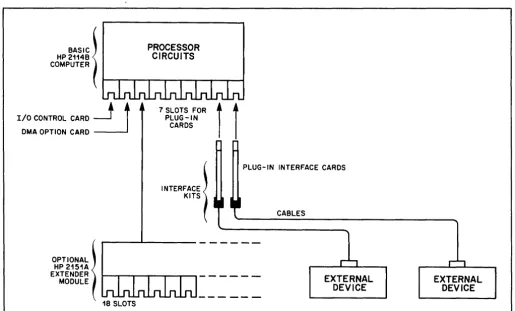
b. Input/Output Options: These options add input and/or output facilities to the basic HP 2114B Computer. The option, identified by an interface kit number (para· graph 2·129), provides the circuitry, cabling, and software to enable the computer to operate with a specific input or output instrument (measuring, reading, or recording device) or with a series of instruments. Compatible instruments, not included in the interface kit, are separately available from Hewlett-Packard. When external devices are connected to the computer, the computer then becomes part of a computer system. (Refer to paragraph 2-4.)
2·4. SYSTEMS. Two general types of computer systems are available from Hewlett-Packard.
a. HP 2114B Computer Systems: Systems may be configured to individual requirements using combinations of standard input/output options. Nonstandard input/ output options, not mentioned in this section or in the computer data sheet, can be obtained on special order; these options are also designated with interface kit acces-sory numbers. The software packages which are hardware dependent (basic control system and system input/output) will be made up in accordance with the hardware system configuration.
b. Data Acquisition Systems: Systems are available in standard configurations which combine Hewlett-Packard digital scanning, measuring, and recording equipment with the HP 2114B Computer. In these systems, the computer is programmed to exercise partial or complete control over the data taking process and to perform computations on data measured by the system. A data acquisition program is furnished with these systems. Capabilities of available instruments include measurements of ac or dc voltages, resistances, frequencies, time periods, temperatures, gas pressures, nuclear events, etc., from multiple inputs. (The functions of some instruments such as linearizers, compara-tors, scanner programmers, and output couplers are present in the basic HP 2114B Computer, or may be accomplished by options or programming.)
2·5. PHYSICAL SPECIFICATIONS.
2-6. POWER REQUIREMENTS.
a. Line voltage: 115 volts ac ± 10 percent (7 amperes) or 230 volts ac ± 10 percent (3.5 amperes) with a special transformer.
b. Line frequency: 47.5 to 66 hertz.
c. Power consumption: 800 watts maximum and 500 watts minimum (computer and teleprinter option only, for minimum value).
d. Power cable: uses a standard three-prong connector.
2-7. ENVIRONMENTAL LIMITS.
a. Temperature: 10° to 40°C (50° to 104°F). b. Relative humidity: to 80 percent at 40°C.
2·8. VENTILATION.
a. Intake at rear and exhaust on sides. b. Air flow: 400 cubic feet per minute. c. Heat dissipation: 2200 BTU /hr, maximum.
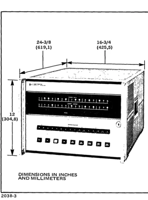
2-9. PHYSICAL DIMENSIONS.
a. Width: 16-3/4 inches with adapters for standard 19 inch rack mounting (see figure 2·1).
b. Panel height: 12 inches. c. Depth: 24.3/8 inches.
d. Recommended cable clearance at rear: 5 inches minimum.
f. Net weight: 106 lb (48 kg). g. Shipping weight: 132lb (59,9 kg).
2038-3
16-3/4 (425,5)
I
• II ,. 'I • III , l , ,. ~ .. • • i I • III
.DODDDDDD
[image:11.623.31.272.85.410.2]DIMENSIONS IN INCHES AND MILLIMETERS
Figure 2-1. HP 2114B Computer Dimensions
2-10. SERVICE ACCESS.
a. The front panel opens, providing access to test switches and protected controls.
b. The top panel slides back and up, permitting top access to input/output connectors, plug-in circuit boards, and wiring.
c. The bottom panel is removable for access to back-plane wiring.
2-11. INPUT/OUTPUT EXTENDERS. The computer has two options for extending its input/output capability. The HP 2151A Input/Output Extender provides an added 17 I/O slots to the basic computer. It can be quickly and easily installed and has its own self-contained power supply. The multiplexed I/O option provides up to 56 I/O channels. Both units make use of the computer's priority interrupt system.
2-12. MACHINE TIMING.
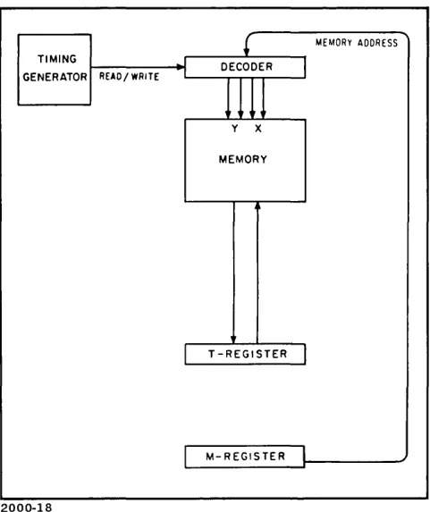
2-13. An internal 8-MHz timing generator automatically generates read/write memory cycles every 2.0 microseconds when running (see figure 2-2). The basic HP 2114B Com-puter has four machine phases (fetch, indirect, execute,
2-2
interrupt) of which the first three include a memory cycle.
If the direct memory access option is installed, a fifth phase is possible, the suspend phase. (Refer to paragraph 2-19.)
2-14. Phases do not occur in a fixed sequence, but rather are determined by conditions which occur during opera-tion. The computer can go directly from one of the first three phases to certain others in the manner indicated in figure 2-2, and an external device can cause the computer to go into the interrupt phase on completion of any current phase. The fetch phase may be thought of as the normal condition; the processing of each instruction begins with a fetch phase, and in many cases is fully executed within that phase. Each phase takes 2.0 microseconds with one excep-tion: the execute phase of the ISZ (increment, and skip if zero) instruction takes 2.5 microseconds .
....
, ~t----MEMORY CYCLE---~""'I
READ WRITE
EXECUTE
FETCH (1 PHASE) OR TO INDIRECT
OR TO EXECUTE TO EXECUTE
INDIRECT OR, REPEAT INDIRECT, OR TO FETCH EXECUTE,
EXECUTE THEN RETURN TO FETCH PHASE TO FETCH
INTERRUPT (NO MEMORY CYCLE) PHASE (AT INTERRUPT LOCATION)
I I I I I
,
o .25 .50 .75 1.0 1.25 1.50 1.75 20
2000-44
Figure 2-2. Machine Timing
2-15. FETCH PHASE. The contents of the currently-addressed memory cell are read into the T-register during the read portion of the memory cycle, and written back into the memory cell during the write portion of the memory cycle. The information left in the T-register is taken as an instruction when read during the fetch phase. If
the instruction is a memory reference instruction, and includes an indirect address bit (refer to paragraph 2-27), the computer sets the indirect phase condition. If the instruction does not have an indirect address bit but is a memory reference instruction, the computer sets the execute phase condition. Otherwise, the current instruction is fully executed at the end of the fetch phase, and the computer remains in the fetch state for the next memory cycle. An exception to these conditions is the JMP (jump) instruction, which is a memory reference group instruction but does not require an execute phase. The computer executes the instruction at the end of the fetch phase or the indirect phase and then sets the fetch phase again for the next memory cycle.
2-16. INDIRECT PHASE. The contents of the memory cell referenced during the fetch phase are read into the T-register and the entire 16-bit word (15 bits of address, plus a new direct/indirect bit) is taken as a new memory reference for the same instruction. The use of 15 bits for an address permits addressing of maximum memory capacity.
If the direct/indirect bit again specifies indirect addressing,
)
the computer remains in the indirect state and reads another 16-bit address word out of memory as a continua-tion of multiple-step indirect addressing. If the direct/ indirect bit specifies direct addressing, the computer sets the execute phase (or, in the case of a jump indirect, the fetch phase).
2-17. EXECUTE PHASE. The 16-bit data word in the memory cell referenced during a fetch phase or an indirect phase is read into the T-register and is operated on by the current instruction (retained from the fetch phase) at the end of the execute phase. At the end of this phase, the computer sets the fetch phase again to read the next instruction.
2-18. INTERRUPT PHASE. An input/output device requesting service at any time during one of the phases is acknowledged at the end of that phase, unless the interrupt is inhibited for any reason by the program being run. The computer then goes into the interrupt phase, which does not have a memory cycle. During this phase, the P-register is decremented so that no instruction in the main program will be skipped or executed twice. At the end of this phase, the interrupt address of the interrupting device is trans-ferred into the M-register and the fetch phase is set to read the instruction contained in the interrupt address location. The interrupt phase cannot occur again until (at least) this instruction is completed.
2-19. SUSPEND PHASE. When the direct memory access accessory kit is installed, a fifth machine phase is used. When the DMA option is ready to make a data transfer between an I/O device and the computer memory, the normal phases are suspended at the completion of the current machine cycle. The DMA option then uses one machine cycle to perform the data transfer. At the end of the suspend phase the computer resumes operation at the point of the DMA interrupt.
2-20. MEMORY.
2-21. TYPE.
2-22. The HP 2114B Computer uses a ferrite core storage module capable of storing 4096 words or 8192 (option 04) words, 17 bits per word (16 bits of the com-puter word, plus a parity bit which is used by memory parity option 02, when included in the instrument).
2-23. LAYOUT.
2-24. The 4096-word module is logically divided into four pages of 1024 words each. A page is defined as the largest block of memory which can be addressed by the memory address bits of a memory reference instruction (excluding the zero/current page bit; see figure 2-3). In the HP 2114B Computer, memory reference instructions have 10 bits to specify a memory address, and thus the page size is 1024 locations (2000 in octal notation). Octal addresses of the four pages of the basic module, and also the double module (which can be added by option 04) are therefore:
Basic Module:
Double Module:
00000 to 01777 02000 to 03777 04000 to 05777 06000 to 07777
10000 to 11777 12000 to 13777 14000 to 15777 16000 to 17777
2-25. ADDRESSING.
2-26. ZERO/CURRENT PAGE. For direct addressing purposes, generally only two pages are of interest: page zero (the base page, consisting of locations 00000 through 01777), and the current page (the page in which the instruction itself is located). All memory reference instruc-tions include a bit (bit 10) reserved to specify one or the other of these two pages. To address locations in any other page, indirect addressing is used (paragraph 2-27). Page references for direct addressing of memory reference instructions are specified by bit 10 as follows:
Logic 0 = Page Zero (Z) Logic 1 = Current Page (C)
2-27. DIRECT /INDIRECT. All memory reference instructions use bit 15 to specify direct or indirect addres-sing. Direct addressing combines the instruction code and the effective address into one word, permitting a memory reference instruction to be executed in two machine phases (fetch and execute). Indirect addressing uses the address part of the instruction word to access another word in memory, which is taken as a new memory reference for the same instruction. This new address word is a full 16 bits long, 15 bits of address plus another direct/indirect bit. The 15-bit length of the address permits access to any location in any module. If bit 15 again specifies indirect addressing, still another address is obtained; this multiple-step indirect addressing may be done to any number of levels. The first address obtained in the indirect phase which does not specify another indirect level becomes the effective address for the instruction. Instructions with indirect addresses are therefore executed in a minimum of three machine phases (fetch, indirect, execute). Direct or indirect addressing is specified by bit 15 as follows:
Logic 0 = Direct Logic 1 = Indirect
2-28. RESERVED LOCATIONS. The first 64 memory locations of the base page (octal addresses 00000 through 00077) are reserved as listed below. The first two addresses are the A and B flip-flop register addresses and are not core storage locations. Locations 5 through 77 are reserved in the sense that interrupt wiring is present for the priority order given. As long as the locations do not have actual interrupt assignments (as determined by the input/output devices included in the user's system), these locations may be used for normal program purposes.
00000 00001 00002 00003 00004
00005 00006 00007 00010 thru 00077
Address of A-register. Address of B-register.
For exit sequence if A and B contents are used as executable words.
Interrupt location, highest priority (re-served for power fail interrupt).
Reserved for memory parity interrupt. Reserved for direct memory access. Not assigned.
Interrupt locations in decreasing order of priority.
2-29. LOADER PROTECTION. The last 64 locations of memory (octal addresses 07700 through 07777 in the standard HP 2114B Computer) are reserved for the basic binary loader. The basic binary loader (not to be confused with the relocating loader program described in paragraph 2-146) is a manually-entered program to permit reading and storage of binary information from punched paper tape, as read by an input device, such as a punched tape reader or a teleprinter. Absolute addresses are required in the loaded data. A protect switch (LOADER ENABLE), when set to NORMAL, protects the basic binary loader locations so that they cannot be altered in any way. For entering the basic binary loader manually into the computer this switch must be set to ON. For actual loading of tapes, both the LOAD and PRESET front panel switches must be pressed simultaneously. The LOADER ENABLE switch is effective for the last 64 locations of memory, regardless of memory size. Plug-in options which expand memory relocate the protected area automatically to the 64 highest numbered locations.
2-30.
WORKING REGISTERS.2-31. The HP 2114B Computer has seven working regis-ters and gives continuous display of the contents of the T (MEMORY DATA) and M (MEMORY ADDRESS) registers by lights on the computer front panel. Five of these are 16 bit flip-flop registers, and two are 1-bit flip-flop registers indicated by panel lighting (on or off) of the register name.
2-32. T-REGISTER (MEMORY DATA). All data trans-ferred into or out of memory is routed through the 16-bit T-register (transfer register). The T-register display there-fore indicates exactly what information went into or out of a memory cell during the preceeding memory cycle.
2-33. P-REGISTER (PROGRAM COUNTER). On com-pletion of each instruction, the P-register indicates the address of the next instruction to be fetched out of mem-ory. The P-register automatically increments by one (or two, when executing a skip instruction) after the execution of each instruction. A jump instruction (JMP or JSB) can set the P-register to any core location number.
2-4
2-34. REGISTER (MEMORY ADDRESS). The M-register holds the address of the memory cell being read or written into. The M-register indication will differ from the P-register indication when multi-phase instructions are being processed, since the M-register will be changed by memory references in the instruction (which may be several in the case of indirect addressing) or by an interrupt, whereas the P-register remains constant until completion of the instruction. The M-register will equal the P-register during the fetch phase.
2-35. A-REGISTER (ACCUMULATOR). The A·register is an accumulator, holding the results of arithmetic and logical operations performed by programmed instructions. This register may be addressed by any memory reference instruction as location 00000, thus permitting inter·register operations such as "add B to A", "compare B with A", etc., using a single·word instruction.
2·36. B·REGISTER (ACCUMULATOR). The B·register is a second accumulator, which can hold the results of arithmetic and logical operations completely independent of the A·register. The B.register may be addressed by any memory reference instruction as location 00001 for inter-register operations with A.
2·37. EXTEND. The extend bit is a one-bit (E) register, and is used to link the A and B registers by rotate instruc· tions or to indicate a carry from bit 15 of the A or B registers by an add instruction (ADA, ADB) or increment instruction (INA or INB, but not ISZ) which references these registers. This is of significance primarily for multiple. precision arithmetic. If already set, the extend bit is not complemented by a carry. It may be cleared, com· plemented, or tested by program instruction. The extend bit is set when the EXTEND panel light is on ("1") and clear when off ("0").
2-38. OVERFLOW. The overflow bit is a one·bit register which indicates, if on, that an add instruction (ADA, ADB) or an increment instruction (INA or INB, but not ISZ) referencing the A· or B·register has caused one of these accumulators to exceed the maximum positive or negative number which can be contained (+32767 or -32768, deci· mal). This condition is implied by a carry (or lack of carry) from bit 14 to bit 15 (paragraph 3·58). By program instruc-tions, the overflow bit may be cleared, set, or tested. The OVERFLOW panel light remains on until the bit is cleared by an instruction and is not complemented if a second overflow occurs before being cleared. It will not be set by shift or rotate instructions.
2-39.
PANEL CONTROLS.2-40. SWITCH REGISTER. The switch register consists of sixteen proximity sense switches used to enter manually-set information into and output data from the computer. The switch register (on is a "1", off is a "0") may be used in the following ways:
)
a. A program may load the switch register setting into the A- or B-register using LIA or LIB instructions with switch register select code 01.
b. A program may merge the switch register setting (inclusive "or") into the A- or B-register using a MIA or MIB instruction, respectively, and a select code of 01.
c. A program may set the switch register by an output from the A- or B-register using OT A or OTB, respectively, and a select code of 01.
d. The switch register setting may be loaded into the P- and M-registers (simultaneously) by using the LOAD ADDRESS switch, thus directing the computer to a specific memory cell.
e. The switch register setting may be entered into the memory cell specified by the M-register by using the LOAD MEMORY switch, thus permitting the user to change the contents of any memory cell.
2-41. PRESET. Momentary proximity switch to preset the computer to the fetch phase, to turn off the interrupt system and all input/output control bits, to set all input/ output flag bits, and to reset the parity halt light located on the computer front panel. It also clears the power fail interrupt circuits. An internal pulse accomplishing the same functions is generated each time power is switched on or off.
2-42. RUN. Momentary proximity switch to start opera-tion at the current state of the computer. Switch is set when a program is running and cleared when the computer halts. When the RUN light is on, all front panel control switches except HALT, and CLEAR REGISTER are disabled.
2-43. HALT. Momentary proximity switch to stop com-puter operation at the end of the current phase. When the computer is halted, the HALT switch is lit and all front-panel control switches are enabled. (The P-register will not increment if the HALT and LOAD MEMORY or HALT and DISPLAY MEMORY switches are touched simultaneou~ly.)
2-44. LOAD. Proximity switch associated with the last 64 locations in memory; for example, octal addresses 07700 through 07777 in 4K computers, or 17700 through 17777 in 8K computers. These locations are normally occupied by the basic binary loader. The LOAD switch is electrically coupled with the PRESET SWITCH. To load any absolute binary program using the last 64 locations of memory, clear the switch register, hold the PRESET button and simultaneously press LOAD. If switch register bit 0 is a "1", the loader program will read the tape and perform a checksum operation but will not alter memory. If the checksum is incorrect, a HLT 00 will occur; otherwise, the computer will go to a normal HLT 77. If bit 15 of the switch register is a "1", the loader program will perform a compare between the program tape and the stored program in memory but will not alter memory. If the taped program does not compare with the program stored in memory, a HLT 00 is generated; otherwise, the computer will go to a
normal HLT 77. If both bit 0 and bit 15 are true, the compare operation will take precedence over the checksum operation.
2-45. LOAD MEMORY. Momentary proximity switch to store the contents of the switch register into the memory location specified by the address in the M-register. The P-and M-registers are automatically incremented after opera-tion of the LOAD MEMORY switch to simplify storing data into consecutive memory locations. (Refer to para-graph 2-43.) The stored data remains displayed in the T-register, and the fetch phase is set at the end of the load operation.
2-46. LOAD ADDRESS. Momentary proximity switch to transfer the contents of the switch register into both the P- and M-registers, thus directing the computer to the desired address. The fetch phase is set at the end of the operation.
2-47. DISPLAY MEMORY. Momentary proximity switch to display, in the T-register, the contents of the location specified by the address in the M-register. The P-and M-registers are automatically incremented after opera-tion of the DISPLAY MEMORY switch so that consecutive memory locations may be displayed simply by repeated operation of this switch. The P- and M-registers are there-fore one step ahead of the T-register display. (Refer to paragraph 2-43.) The fetch phase is set after incrementing the P-and M-registers.
2-48. SINGLE CYCLE. Momentary proximity switch to execute one machine cycle each time the switch is pressed. The interrupt phase is not recognized in this mode.
2-49. CLEAR REGISTER. Momentary proximity switch to reset the switch register to "0".
2-50. PROTECTED CONTROLS.
2-51. POWER ON/OFF switch located behind the front panel on the computer chassis. Contents of memory are not affected by switching power off and on; contents of the working registers, however, are lost when power goes off (contents random following turn-on).
2-52. LOADER ENABLE ON/NORMAL switch located on the inside of front panel. The NORMAL position pro-tects the basic binary loader (located in the last 64 positions in memory) making it available for loading tapes. The ON position allows the basic binary loader program to be loaded or changed.
2-53.
INSTRUCTIONS.2-54. NUMBER. The HP 2114B Computer has 70 basic one-word instructions, all executable in 2.0 or 4.0 seconds (except for ISZ, which is executable in 4.5 micro-seconds). These instructions are grouped in three types, described in paragraphs 2-60 through 2-104. Combinations of the register reference microinstructions, which are all
one-word instructions, executable in 2.0 microseconds, extend the total of different one-word instructions to over 1000.
2-55. FORMATS.
2-56. The three types of basic instructions are grouped according to the bit format of the instruction word. These types are: memory reference, register reference, and input/ output instructions. A comparison of the three formats is given in figure 2-3, and detailed binary coding is included with the instruction descriptions following. A consolidated coding table appears in the appendix of this manual.
1
2
3
15 14 13 12 II 10 9 e 7 6 5 4 3 2 1 0
.1 • • • 1 • • • 1 • • • 1 • • • 1 • • •
OIL
I
INSTRUCTIONI
Z/cI
MEMORY ADDRESS REG. REF. GROUPI
REGISTER MICROINSTRUCTIONSI/O GROUP
I
INSTRUCTIONJ
SELECT CODE1 MEMORY REFERENCE INSTRUCTIONS 2 REGISTER REFERENCE INSTRUCTIONS 3 INPUT/OUTPUT INSTRUCTIONS
2000-5
Figure 2-3. Basic Instruction Formats
2-57. The first type comprises the memory reference instructions, using 10 bits (0 through 9) for a memory address, bit 10 to specify zero or current page, and bit 15 for direct or indirect addressing. This leaves four bits (14, 13, 12, 11) to encode the 14 instruction commands in this group.
2-58. The other two types use four bits (15, 14, t3, 12) to distinguish the register reference and the input/output instructions. The register reference type uses bits 11 through 0 to combine up to eight microinstructions (Le., instructions formed by only 1, 2, or 3 bits), with the resulting multiple instruction operating on the A-, B-, or E-register as a single-word instruction. The input/output type uses bits 11 through 6 for a variety of input/output instructions and bits 5 through 0 to make the instruction apply directly to one of the input/output devices or functions.
2-59. The following paragraphs describe in detail each of the instructions in the three type groups.
2-6
Note
Functions of bits appearing in the form A/B, D/I, D/E, Z/C, or H/C throughout these specifications are obtained by coding
"a"
or "1" respectively (0/1). For example, A is specified by a zero-bit, and B by a one-bit.2-60. MEMORY REFERENCE INSTRUCTIONS.
2-61. The 14 memory reference instructions execute some operation involving memory locations, such as trans-ferring information in or out of a memory cell or checking the memory cell contents. The cell referenced (Le., the absolute address) is determined by a combination of the ten memory address bits in the instruction word (0 through 9) and five bits (10 through 14) assumed from the current condition of the P-register. This means that memory refer-ence instructions can directly address any word in the current page; additionally, if the instruction is given in some location other than the base page (page zero), bit 10 of the instruction word doubles the addressing range to 2048 words by allowing selection of either page zero or current page (Le., bits 10 through 14 of the address in the M-register can be reset to zero, instead of assuming the current indication of the P-register). This feature provides a convenient linkage between all pages of memory, since page zero can be reached directly from any other page.
2-62. Note that since the A- and B-registers can be addressed (paragraphs 2-35 and 2-36), any memory refer-ence instruction can apply to either of these registers as well as to memory cells. For example, ADA 0001 means add the contents of the B-register (its address being 0001) to the A-register; specify page zero for these operations, since the A and B register addresses are on page zero.
2-63. Figure 2-4 gives instruction codes and mnemonics for all 14 memory reference instructions. All memory ref-erence instructions take a minimum of two machine phases (one to read the instruction word, and one to read the referenced memory cell), except for JMP, which is a one-phase instruction. Logic truth tables relating to the first three instructions described below are given in table 2-1. Note that logic operations are performed on a bit-for-bit basis (Le., no carries).
15 14 13 12 11 10 9 8 7 6 5 4 3 2
,
0.1 • • • 1 • • • 1 • • • 1
• •• 1.
• •
10/rl
INSTRUCTIONI
Z/e!
MEMORY ADDRESSAND 0 0 1 0
XOR 0 1 0 0
lOR 0 1 1 0
JSB 0 0 1 1
JMP 0 1 0 1
ISZ 0 1 1 1
ADA 1 0 0 0
ADB 1 0 0 1
CPA 1 0 1 0
CPB 1 0 1 1
LDA 1 1 0 0
LDB 1 1 0 1
STA 1 1 1 0
STB 1 1 1 1
[image:15.627.294.537.495.715.2]2000-6
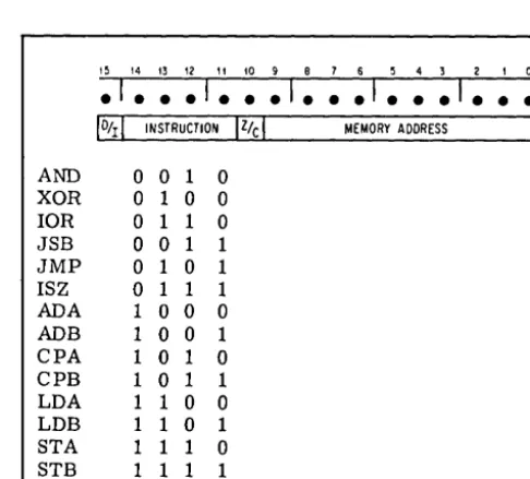
Figure 2-4. Memory Reference Instructions
)
Table 2-1. Logic Truth Table
AND XOR lOR
A-Register 001 1 001 1
o
0 1 1 ContentsMemory
o
1 0 1 010 1 010 1Result (in 000 1
o
1 1 0o
1 1 1 A-Register)1 = True, 0= False
2-64. AND: "And" to A. The contents of the addressed location are logically "anded" to the contents of the A-register. The contents of the memory cell are left unaltered.
2-65. XOR: "Exclusive or" to A. The contents of the addressed location are combined with the contents of the A-register as an "exclusive or" logic operation. The con-tents of the memory cell are left unaltered.
2-66. lOR: "Inclusive or" to A. The contents of the addressed location are combined with the contents of the A-register as an "inclusive or" logic operation. The contents of the memory cell are left unaltered.
2-67. JSB: Jump to Subroutine. This instruction, exe-cuted in location P, causes computer control to jump unconditionally to the memory location (X) specified in the address portion of the JSB instruction word. The contents of the P-register plus one (return address) is stored in location X, and the next instruction to be executed will be that contained in the next location (X + 1). A return to the main program sequence at P + 1 may be effected by a jump indirect through location X.
2-68. JMP: Jump. This instruction transfers control to the addressed location. That is, JMP causes the P- and M-registers to be set according to the memory address portion of the instruction word, thus addressing memory cell X, so that the next instruction will be read from location X.
2-69. ISZ: Increment, and skip if zero. An ISZ instruc-tion adds one to the contents of the addressed memory location. If the result of this operation is zero, the next instruction is skipped; i.e., the P- and M-registers are advanced by two instead of one. Otherwise, the program proceeds normally to the next instruction in sequence. The incremented value is written back into the memory cell in either case. An ISZ instruction referencing locations zero or one (A- or B-register) cannot cause setting of the extend or overflow bits (unlike INA and INB).
2-70. ADA: Add to A. The contents of the addressed memory location are added to the contents of the A-register, and the sum remains in the A-register. The result of the addition may set the extend or overflow bits (para-graphs 2-37 and 2-38). The contents of the memory cell are unaltered.
2-71. ADB: Add to B. The contents of the addressed memory location are added to the contents of the B-register, and the sum remains in the B-register. Extend or overflow bits may be set, as for ADA. The contents of the memory cell are unaltered.
2-72. CPA: Compare to A, skip if unequal. The contents of the addressed location are compared with the contents of the A-register. If the two 16-bit words are different, the next instruction is skipped; i.e., the P- and M-registers are advanced by two instead of one. If the words are identical, the program proceeds normally to the next instruction in sequence. The contents of neither the A-register nor the memory cells are altered.
2-73. CPB: Compare to B, and skip if unequal. Same as CP A, except comparison is made with B-register.
2-74. LDA: Load into A. The A-register is loaded with the contents of the addressed location. The contents of the memory cell are unaltered.
2-75. LDB: Load into B. The B-register is loaded with the contents of the addressed location. The contents of the memory cell are unaltered.
2-76. STA: Store A. The contents of the A-register are stored in the addressed location. The previous contents of the memory cell are lost; the A-register is unaltered.
2-77. STB: Store B. The contents of the B-register are stored in the addressed location. The previous contents of the memory cell are lost; the B-register is unaltered.
2-78. REGISTER REFERENCE INSTRUCTIONS.
2-79. The register reference instructions, in general, manipulate bits in the A-, B-, and E-registers. There is no reference to memory; thus these instructions are executed in only one machine phase. This type includes 39 basic instructions, which are combinable to form a one-word multiple instruction that can operate in various ways on the contents of the A-, B-, or E-registers. These microinstruc-tions are divided into two subgroups, the shift-rotate group (SRG) and the alter-skip group (ASG). Three instructions (SLA, SLB, and CLE) appear in both groups and, being combinable in these different contents, are counted twice in the total of basic instructions. Microinstructions may be combined under the following general rules:
a. Instructions from the two groups cannot be mixed.
b. References to both A and B registers cannot be mixed.
c. Only one microinstruction can be chosen from each column of the selection tables in figure 2-5 and 2-6.
d. Use zeros to exclude unwanted microinstruction bits.
e. The sequence of execution is left to right in the selection tables (column 1, then column 2, etc.).
f. If two (or more) skip functions are combined, the skip will occur if either or both conditions are met. One exception exists for the RSS instruction (paragraph 2-82).
2-80. Register Reference. Instructions are recognized by the computer when the four most significant bits of the instruction word are zeros; the general format for this type of instruction (the dots representing variable microinstruc-tion bits) is therefore:
15 14 13 12 11 10 9 8 7 6 543 210 0 0 0 0
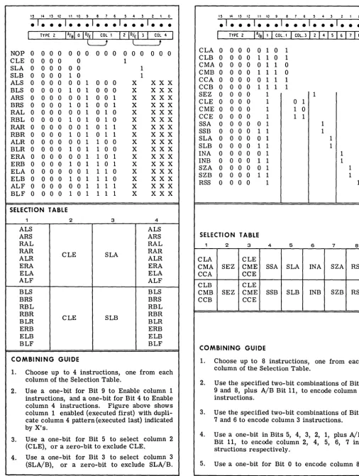
2-81. SHIFT-ROTATE GROUP. The SRG instructions are specified by a zero for bit 10. (Compare figures 2-5 and 2-6.) Figure 2-5 gives both the bit format and the selection table for using these instructions. Definitions for the mne-monics used are listed below. Note that the extend bit is not affected by shifts or rotates unless specifically stated. All of the shift and rotate instructions can be executed either first or last in a combined instruction, or both times. This permits sequencing of CLE and SLA/B either before or after shifts and rotates.
NOP No operation. Memory read/write cycle only.
CLE Clear E-register.
SLA Skip next instruction if least significant bit of A-register is zero (i.e., skip if an even number is in A-register).
SLB Skip next instruction if least significant bit of B-register is zero (i.e., skip if an even number is in B-register).
ALS A-register left shift one place, arithmetically (15 bits only). A zero replaces vacated bit 0; bit shifted out of bit 14 is lost; bit 15 (sign bit) is not affected.
BLS B-register left shift one place, arithmetically (15 bits only). A zero replaces vacated bit 0; bit shifted out of bit 14 is lost; bit 15 (sign bit) is not affected.
ARS A-register right shift one place, arithmetically. Bit shifted out of bit 0 is lost; copy of sign bit (bit 15) shifted into bit 14; bit 15 is not affected.
BRS B-register right shift one place; arithmetically. Bit shifted out of bit 0 is lost; copy of sign bit (bit 15) shifted into bit 14; bit 15 is not affected.
RAL Rotate A-register left one place, all 16 bits. Bit 15 is rotated around to bit O.
2-8
RBL Rotate B-register left one place, all 16 bits. Bit 15 is rotated around to bit O.
RAR Rotate A-register right one place, all 16 bits. Bit
o
is rotated around to bit 15.RBR Rotate B-register right one place, all 16 bits. Bit
o
is rotated around to bit 15.ALR A-register left shift one place, same as ALS, but clear sign bit after shift.
BLR B-register left shift one place, same as BLS, but clear sign bit after shift.
ERA Rotate E-register right with A-register, one place (17 bits). Bit 0 is rotated into extend-register; extend content is rotated into bit 15.
ERB Rotate E-register right with B-register, one place (17 bits). Bit 0 is rotated into extend-register; extend content is rotated into bit 15.
ELA Rotate E-register left with A-register, one place (17 bits). Bit 15 is rotated into extend-register; extend content is rotated into bit O.
ELB Rotate E-register left with B-register, one place (17 bits). Bit 15 is rotated into extend-register; extend content is rotated into bit O.
ALF Rotate A-register left four places, all 16 bits. Bits 15 14 13 12 are rotated around to bits 3, 2, 1,
o
'resp'ecti~ely.
Equivalent to four successive RAL instructions.BLF Rotate B-register left four places, all 16 bits. Bits 15, 14, 13, 12 are rotated around to bits 3, 2, 1,
o
respectively. Equivalent to four successive RBL instructions.2-82. ALTER-SKIP GROUP. The ASG instructions are specified by a "1" in bit 10. Figure 2-6 gives both the bit format and the selection table for using these instruc-tions. Definitions for the mnemonics are used as follows:
CLA Clear A-register.
CLB Clear B-register.
CMA Complement A-register. One's complement, reversing the state of all 16 bits.
CMB
Co~plement
B-register. Reverses state of all 16 bits.CCA Clear, then complement A-register. Puts 16 ones in the A-register; this is the two's complement form of-1.
CCB Clear, then complement B-register. Puts 16 ones in the B-register; this is the two's complement form of-1.
)
1~ 14 13 12 11 10 9 8 7 6 ~ 4 3 2 1 0
.1 • • •
1 • • •1 • • • 1 • • • 1 • • •
TYPE 2
IAtalolog'
121%131 COL 4I
l
tNOP 0 0 0 0
CLE 0 0 0 0
SLA 0 0 0 0
SLB 0 0 0 0
ALS 0 0 0 0
BLS 0 0 0 0
ARS 0 0 0 0
BRS 0 0 0 0
RAL 0 0 0 0
RBL 0 0 0 0 RAR 0 0 0 0
RBR 0 0 0 0
ALR 0 0 0 0
BLR 0 0 0 0
ERA 0 0 0 0
ERB 0 0 0 0
ELA 0 0 0 0
ELB 0 0 0 0
ALF 0 0 0 0
BLF 0 0 0 0
0 0 0 0 0 0
o
o
01 0
o
0 1 0 0 0 1 0 1 0 0 0 0 0 1 0 0 1 1 0 1 0 0 1 0 0 1 0 1 0 1 0 1 0 1 0o
0 1 0 1 1 1 0 1 0 1 1 0 0 1 1 0 0 1 0 1 1 0 0 0 0 1 1 0 1 1 0 1 1 0 1 0 0 1 1 1 0 1 0 1 1 1 0 0 0 1 1 1 1 1 0 1 1 1 1SELECTION TABLE
ALS ARS RAL RAR ALR ERA ELA ALF BLS BRS RBL RBR BLR ERB ELB BLF 2 CLE CLE
COMBINING GUIDE
3
SLA
SLB
0 0 0 0 0 0 1
1 1
X X X X X X X X X X X X X X X X X X X X X X X X X X X X X X X X X X X X X X X X X X X X X X X X X X X X X X X X X X X X
X X X X
4 ALS ARS RAL RAR ALR ERA ELA ALF BLS BRS RBL RBR BLR ERB ELB BLF
1. Choose up to 4 instructions, one from each column of the Selection Table.
2. Use a one-bit for Bit 9 to Enable column 1
instructions, and a one-bit for Bit 4 to Enable column 4 instructions. Figure above shows column 1 enabled (executed first) with dupli-cate column 4 pattern (executed last) indicated by XIS.
3. Use a one-bit for Bit 5 to select column 2 (CLE), or a zero-bit to exclude CLE.
4. Use a one-bit for Bit 3 to select column 3 (SLA/B), or a zero-bit to exclude SLA/B.
[image:18.624.65.571.58.728.2]2000-7
Figure 2-5. Shift-Rotate Instructions
1 5 14 13 12 11 10 9 8 7 6 ~ 4 3 2 1 0
.1 • • • 1 • • • 1 • • • 1 • • • 1 • • •
I
TYPE 2I
%
I
II
COL. II
COL.3I
2I
4I
5I
6I
7I
8I
CLA 0 0 0 0 0
CLB 0 0 0 0 1
CMA 0 0 0 0 0
CMB 0 0 0 0 1
CCA 0 0 0 0 0
CCB 0 0 0 0 1
SEZ 0 0 0 0
CLE 0 0 0 0
CME 0 0 0 0
CCE 0 0 0 0
SSA 0 0 0 0 0
SSB 0 0 0 0 1
SLA 0 0 0 0 0
SLB 0 0 0 0 1
INA 0 0 0 0 0
INB 0 0 0 0 1
SZA 0 0 0 0 0
SZB 0 0 0 0 1
RSS 0 0 0 0
SELECTION TABLE
2 3
CLA CLE
CMA SEZ CME
CCA CCE
CLB CLE
CMB SEZ CME
CCB CCE
COMBINING GUIDE
1 0 1 1 0 1 1 1 0 1 1 0 1 1 1 1 1 1
1 1 1 1 1 1 1 1 1 1 1 1 1
4 5
o
1 1 0 1 1SSA SLA
SSB SLB
1 6 INA INB 1 1 1 1 1 1 1 1 1
7 8
SZA RSS
SZB RSS
1. Choose up to 8 instructions, one from each column of the Selection Table.
2. Use the specified two-bit combinations of Bits 9 and 8, plus AlB Bit 11, to encode column 1 instructions.
3. Use the specified two-bit combinations of Bits 7 and 6 to encode column 3 instructions.
4. Use a one-bit in Bits 5, 4, 3, 2, 1, plus A/B Bit 11, to encode column 2, 4, 5, 6, 7 in-structions respectively.
5. Use a one-bit for Bit 0 to encode column 8.
2000-8
Figure 2-6. Alter-Skip Instructions
CLE Clear E-register.
CME Complement E-register. Reverses state of the extend bit.
CCE Clear, then complement E-register. Sets the extend bit.
SEZ Skip the next instruction if E-register is zero.
SSA Skip next instruction if sign bit (bit 15) of A-register is zero; Le., skip if the content of A is positive.
SSB Skip next instruction if sign bit (bit 15) of B-register is zero; i.e., skip if the content of B is positive.
SLA Skip next instruction if least significant bit of A-register is zero (Le., skip if an even number is inA).
SLB Skip next instruction if least significant bit of B-register is zero (Le., skip if an even number is in B).
INA Increment A-register by one. Can cause setting of extend or overflow bits (paragraphs 2-37 and 2-38).
INB Increment B-register by one. Can cause setting of extend of overflow bits (paragraphs 2-37 and 2-38).
SZA Skip next instruction if A-register is zero (16 zeros).
SZB Skip next instruction if B-register is zero (16 zeros).
RSS Reverse skip sense. Skip occurs for any of the preceding skip instructions, if present, when the non-zero condition is met. RSS without a skip instruction in the word causes an unconditional skip. If a word with RSS also includes both SSA/B and SLA/B, bits 15 and 0 must both be one for skip to occur; in all other cases the skip occurs if either or both conditions are met.
2-83. INPUT/OUTPUT INSTRUCTIONS.
2-84. The HP 2114B Computer has 17 basic input/ output instructions, which provide the following general capabilities.
a. Fix the state of the flag, control, and overflow bits. (These bits are described in paragraphs 2-111 and 2-38.)
b. Test the state of the flag and overflow bits (Le., skip if set or clear, as specified).
c. Enter data from a specific device into the A- or B-register.
2-10
d. Output data to a specific device from the A- or B-register.
e. Halt the program.
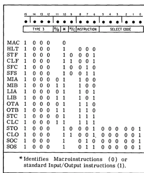
2-85. Input/output instructions are recognized by the computer when the four most significant bits of the instruc-tion word are 1000 and bit 10 is al
"1". The codes and mnemonics for all 17 instructions are given in figure 2-7 (the MAC instruction is not counted as a basic instruction; see paragraph 2-87). All input/output instructions are executed in one cycle (the fetch phase).
2-86. Note that bit 11, where relevant, specifies A- or B-register; otherwise it may be "1" or "0" without affecting the instruction, although the assembler will assign zeros (as shown). Bit 9, where not specified, offers the choice of holding (0) or clearing (1) the device flag after execution of the instruction. (Exception: the H/C bit asso-ciated with the last two instructions in this list holds or clears the overflow bit instead of the flag bit.) Bits 8, 7, and 6 identify the instruction; some of the instructions, how-ever, require additional specific bits for the complete code. Bits 5 through 0 form select codes to make the instruction apply to one of up to 64 input/output devices or functions (see paragraph 2-107).
2-87. The MAC instruction listed in figure 2-7 is avail-able to provide up to 2048 entries to macroinstruction subroutines. Since it is used only by special options and special software, MAC is not counted as one of the 70 basic machine instructions. The basic HP 2114B will treat MAC as a no-operation (NOP) instruction.
15 14 13 12 11 10 9 8 7 6 5 4 3 2 I 0
.1 ••
• 1 • • • 1 • • • 1 • • • 1 • • •I
TYPE 31% 1"*
IH/d'NSTRUCTIONI
SELECT CODEI
MAC 1 0 0 0 0
HLT 1 0 0 0 1 0 0 0
STF 1 0 0 0 1 0 0 0 1 CLF 1 0 0 0 1 1 0 0 1 SFC 1 0 0 0 1 0 0 1 0 SFS 1 0 0 0 1 0 0 1 1 MIA 1 0 0 0 0 1 1 0 0
MIB 1 0 0 0 1 1 1 0 0 LIA 1 0 0 0 0 1 1 0 1 LIB 1 0 0 0 1 1 1 0 1 OTA 1 0 0 0 0 1 1 1 0 OTB 1 0 0 0 1 1 1 1 0 STC 1 0 0 0 0 1 1 1 1 CLC 1 0 0 0 1 1 1 1 1
STO 1 0 0 0 1 0 0 0 1 0 0 0 0 0 1 CLO 1 0 0 0 1 1 0 0 1 0 0 0 0 0 1
SOC 1 0 0 0 1 0 1 0 0 0 0 0 0 1
SOS 1 0 0 0 1 0 1 1 0 0 0 0 0 1
*
Identifies Mac roinstructions (0) or standard Input/Output instructions (1). [image:19.620.302.545.431.721.2]2000-9
Figure 2-7. Input/Output Instructions
2·88. HLT. Halt. Stops the computer and holds or clears the flag (according to bit 9) of any desired input/output device (bits 5 through 0). The HLT instruction has the same effect as the HALT pushbutton: the HALT switch lights, all front·panel control switches are enabled, and no interrupts may occur. The HLT instruction will be displayed in the T·register, and the M·register will normally indicate the HALT location plus one.
2·89. STF. Set flag. Sets the input/output flag of the selected device, thus causing an interrupt during the next machine phase if the interrupt system is enabled (paragraph 2·113), and the corresponding control bit is set. The inter· rupt system itself is enabled by an STF instruction with a select code of 6 zeros (octal 00).
2·90. CLF. Clear flag of selected device. Resets the flag, thus permitting the device to present another flag when ready again. A CLF with a select code of 6 zeros (octal 00) disables the entire interrupt system; this does not affect the status of individual input/output flags.
2·91. SFC. Skip if flag clear. Causes the computer to skip the next instruction if the flag bit of the selected device is zero (Le., the device is not ready).
2·92. SFS. Skip if flag set. The next instruction is skipped if the flag bit of the selected device is one (Le., the device is ready).
2·93. MIA. Merge input into A. The contents of the input/output buffer associated with the selected device are merged ("inclusive or") into the A·register.
2·94. MIB. Merge input into B. The contents of the input/output buffer associated with the selected device are merged ("inclusive or") into the B·register.
2·95. LIA. Load input into A. The contents of the input/output buffer associated with the selected device are loaded into the A·register. Previous contents of the A· register are lost.
2·96. LIB. Load input into B. The contents of the input/output buffer associated with the selected device are loaded into the B·register. Previous contents of the B· register are lost.
2·97. OT A. Output from A. The contents of the A· register are loaded into the input/output buffer associated with the selected device. If the buffer is less than 16 bits in length, the least significant bits of the A·register normally are loaded. (Some exceptions exist, depending on the type of output device.) A·register contents are not altered.
2·98. OTB. Output from B. The contents of the B· register are loaded into the input/output buffer associated with the selected device.
2·99. STC. Set control bit of the selected device. This commands or prepares the device to perform its input or output function, and enables its flag bit to interrupt the program being run (provided the program is not disabling the interrupt system).
2·100. CLC. Clear control bit of the selected device. This prevents the device from interrupting. A CLC instruc· tion with a select code of 00 (octal) clears all control bits, effectively turning off all input/output devices. CLF 00 may be combined with this to additionally turn off the interrupt system.
2·101. STO. Set overflow. The overflow bit remains set until cleared by one of the following three instructions.
2·102. CLO. Clear overflow. Resets the overflow register.
2·103. SOS. Skip if overflow set. If the overflow register is set, the next instruction of the program is skipped. Use of the H/e bit will hold or clear the overflow bit following execution of this instruction (whether the skip is taken or not).
2·104. SOC. Skip if overflow clear. If the overflow regis· ter is clear, the next instruction of the program is skipped. Use of the H/C bit will hold or clear the overflow bit following execution of this instruction.
2·105. DATA FORMATS.
2·106. Data is represented in two's complement form internally in the computer. The basic format for arithmetic operations on numerical data is defined in figure 2·8. The data is assumed to be an integer (binary point to the right of bit 0), and is positive if the sign bit is "0", or negative if "1". The largest possible positive number (in octal) is +77777, or (in decimal) +32767; the largest possible nega· tive number is -100000 (octal) or -32768 (decimal). Other possible formats, including packed data words, double· length fixed point, and floating point representations, are defined in standard software packages.
15 14 13 12 I I 10 9 8 7 6 5 4 3 2 I 0
.1 • • • 1 • • • 1 • • • 1 • • • 1 • • •
i
'
v/j
MAGNITUDE MAGNITUDE
SIGN
2000-10
Figure 2-8. Basic Data Format
2·107. INPUT/OUTPUT SPECIFICATIONS.
2·108. INPUT/OUTPUT SYSTEM DESIGN.
BINARY POINT