A Flexible Multichannel Digital Random
Pulse Generator Based on FPGA
Mohammad Arkani1,2, Hossein Khalafi2*, Naser Vosoughi3 1Physics Department, Amir-Kabir University of Technology, Tehran, Iran
2Radiation Application Research School, Nuclear Science & Technology Research Institute (NSRTI), Atomic Energy Organization of Iran (AEOI), Tehran, Iran
3Department of Energy Engineering, Sharif University of Technology, Tehran, Iran Email: *[email protected]
Received June 19, 2013; revised July 21, 2013; accepted August 9, 2013
Copyright © 2013 Mohammad Arkani et al. This is an open access article distributed under the Creative Commons Attribution Li-cense, which permits unrestricted use, distribution, and reproduction in any medium, provided the original work is properly cited.
ABSTRACT
The present paper describes a multichannel digital random pulse generator implemented in a 65-nm FPGA device. The random time interval generation is based on inverse transformation method. The output pulse generation rate, pulse width and the probability distribution function (PDF) of each channel might be individually selected by the computer through a USB cable connection. Statistical properties of the output channels can be adjusted and recorded in a fully dynamic flexible manner. The Poisson and uniform PDFs were tested and implemented for up to eight different chan- nels in experiment, however, the implementation of any arbitrary PDF is possible by programming capability of the de- vice as well. Detailed experimental results are expressed in the manuscript. The proposed equipment makes it possible to verify the complicated multichannel detection systems without having the radioactive experimental tests. This is a low cost instrumentation due to the FPGA-based construction.
Keywords: Field Programmable Gate Array (FPGA); Random Pulse Generator; Probability Distribution Function
1. Introduction
Nuclear particle detection is a stochastic process. Having a random pulse generator with a known PDF is an essen- tial tool for a range of experimental laboratory tests and verifications of nuclear instrumentation modules (NIMs) [1-6]. A good example of a random pulse generator is the work done by Ponikvar [7] for testing and calibrating of dead time correction algorithms in spectroscopy systems. It is a digital random pulse generator with TTL compati- ble based on Pseudo Random Bit Sequence (PRBS) tech- nique. The rate of pulse generation can be set to different values from 2.5 kP/s to 100 kP/s. That is controllable in steps of 2.5 kP/s. The minimum achievable time interval between two successive random pulses is 97.6 ns. All pulses have a fixed duration equal to 49 ns. The instru- ment suffers from the limited capability of output para- meters adjusting. Abdel-Aal [8] has proposed a random pulse generator with a greater flexibility in selecting the desired statistical properties of the output pulses by soft- ware control basis. Ferrucci [9] has developed a FPGA- based random pulse generator for emulation of neutron
detectors. The developed random pulse generator is bas- ed on Bernoulli trials ranging from 0.5 P/s to 1 MP/s. Neutron detection systems of nuclear reactors might be emulated in start-up and shutdown regimes by the men- tioned equipment. This equipment can help the mainten- ance team to check and verify the electronic circuitry of the detection systems of nuclear reactors in a safe and re- liable condition.
Analogue random pulse generators are also developed as reported in the literature [10-12]. In analogue designs, features of the output pulses are controlled via an analo- gue parameter like resistor or voltage of the circuitry. Therefore, the generator shall be facilitated with an ap- propriate measuring device to indicate the statistical pa- rameters of the generated pulses. One of the advantages of digital implementation is the possibility of setting the output parameters accurately. This feature was well-de- fined in the present work as a built-in function of the in- novative design to adjust different parameters of the out- put channels.
timing characteristics of the output pulses and the li- mited output pulse generation rate (no more than several thousand pulses per second is possible). Therefore, hard- ware implementation is preferred at the expense of prac- tical complications for accurate tests. Anyhow, software programming is preferred while the hardware implemen- tation of an arbitrary function is not possible.
The current paper presents an investigation about the digital hardware implementation of an arbitrary random pulse generator by the aid of HDL programming and FPGA technology. The method is potentially capable to be applied to any arbitrary analytical PDF since the ana- lytical functions are solved.
Random Time Interval Generation Based on Inverse Transformation Method
In this part, related theory for generation of uniform and Poisson random time intervals based on inverse trans- formation method is presented. Firstly, this is defined for Poisson PDF. Then in a similar way, the results for uni- form PDF are described as well.
The probability of adjacent random events in Poisson PDF is a well-known relation [13,14]. By integration of the PDF in the limits of time interval of two successive events, the result would be the probability of the next event. Equating the integration result (CDF) to the nor- malized random number
results in Equation (1):Poisson Poisson 0 1 t nt nt
ne dt e
(1)The time interval might be expressed by rearrange- ment of Equation (1) as:
Poisson
1 1
t Ln
n
(2)
where tPoisson is the time interval of the next event with
Poisson PDF. Time is assumed as a discrete parameter by a reference clock in digital circuits. Therefore, the time interval between pulses is counted by the number of dig- itization periods:
Poisson
Poisson Poisson Poisson
1 Ln t
N K
T n T
f
(3)
Poisson 1
f Ln
Poisson 1 K n T
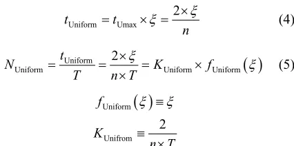
Similarly, for a uniform PDF, the uniform time inter- val variable1 Uniform Umax 2 t t n
(4)
Uniform
Uniform Uniform Uniform
2
t
N K
T n T
f
(5)
Uniform
f
Unifrom 2 K n T
Generally, number of digitization periods between two successive random events can be written as Equation (6):
N K f (6)
K is a constant which depends on the digitization pe- riod and the average pulse generation rate. While, f
is a maths function which operates on . This is the ba- sic idea behind the proposed method. Solution of random time interval needs arithmetic operations. Using FPGA technology, the hardware-based arithmetic operations are possible. [image:2.595.325.538.85.191.2]2. Methods and Results
Figure 1 shows the schematic diagram of the multichan-
nel random pulse generator. A 32-bit integer pseudoran- dom number generator2 is used to generate uniform ran-
dom numbers. Then, they are converted to 32-bit IEEE floating point format [15]. The random numbers are nor- malized between [0, 1] interval to generate the number of digitization periods with selected PDF by the block la-belled as “Arithmetic IP cores”. This block performs the arithmetic floating-point operations (Equations (3) and (5)) using the dedicated hardware for high speed and ac- curate random time interval generation. A comprehensive explanation about the arithmetic operations is given in the next section. FIFO memory is necessary as a tempo- rary memory buffer for data saving because of stochastic principal of pulse generation. The generated random time interval stored in FIFO memory buffer is fetched by a written VHDL code to generate the output pulses. Relat- ed hardware and timing of the system are synchronized with the clock provided by the PLL. Average output pulse generation rate, pulse width, and PDF of each channel are adjusted by the Nios II processing core [16] through USB cable connection to the computer and its intercon- nections to different parts of the design. Figure 1 shows more information in details. The maximum working fre- quency is practically determined. It depends on the com- plexity of the architecture and the speed characteristics of the device. Detailed experimental features of the archi-
ecture are reflected in Table 1 for one-channel and
1 and the corresponding number of digitiza-
tion periods can be expressed as Equations (4) and (5): t
2Linear Feedback Shift Register (LFSR) technique is utilized. The
ab-solute value of the random number is used as a uniform random num-ber variable.
Table 1. Experimental test results comparing the amount of provided hardware resources and the maximum possible per- formance for different number of output channels.
FPGA Family (Device Code) STRATIX III (EP3SL150F1152C2N)a
Number of Output Channels 1 8
Logic ElementsTotal (%Used) 113600 (%7) 113600 (%32)
FPGA Memory BitsTotal (%Used) 5630976 (%15) 5630976 (%23)
DSP BlocksTotal (%Used) 384 (%13) 384 (%71)
PLLsTotal (Used) 8 (2) 8 (2)
32-bit FIFO Memory Depth 1 × 2048 8 × 2048
Maximum Digitization Frequency(Minimum Digitization Period) 200 MHz (5 ns) 200 MHz (5 ns)
Minimum Inter Event Dead Timeb(= Minimum Output Pulse Width + 5 ns) 15 ns 15 ns
Maximum Output Pulse Generation Ratec 6 MP/s 750 kP/s (each channel)
Adjustable Output Pulse Widthd 10 ns to (216 × 5 ns) 10 ns to (216 × 5 ns)
Selectable Probability Distribution Functione Uniform/Poisson Uniform/Poisson
Nios II on Chip Memory Size 25 kB 25 kB
aExperimental verification tests on the STRATIX III device [18] are accomplished by STRATIX III DSP Development Kit [19]. bAt least three digitization
periods are needed to finalize each pulse generation process. cThe maximum output pulse generation rate depends on minimum inter event dead time and the
maximum random number generation rate. A detailed description is explained in Section 4. dThe output pulse width increases the inter event dead time. There-
fore, at high generation rates the output pulses must be narrow enough. eImplementation of any arbitrary probability function is also possible.
[image:3.595.72.531.392.711.2]eight-channel structures.
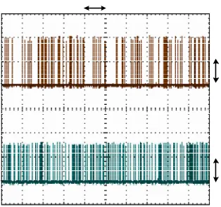
Figure 2 shows the captured information of the ran-
dom pulses by a typical laboratory digital oscilloscope.
In Figure 2, random pulses generated by channels 1 and
2 are demonstrated. These channels have different PDFs with the same selected pulse generation rate. More ex- planation about the results will be given shortly in next sections.
2.1. Use of IP Cores in Hardware-Based Arithmetic Operations
Wide varieties of configurable IP cores of different sizes and complexities optimized for FPGAs have been pro- vided. Therefore, performing the arithmetic operations by HDL programming is readily possible [17]. Figure 3 shows the method of hardware based implementation of arithmetic operations for Poisson random time interval generation. The random number generated by LFSR and the coefficient KPoisson determined by the NIOS II proc-
essing core are integer inputs of the blocks. They are converted to floating point numbers to be operated by the next arithmetic operations.
The floating point random number is normalized and inverted to generate the fPoisson(ξ) by the Natural Loga-
rithm Block. Finally, NPoisson is calculated and the result
is converted to integer format to be stored by FIFO me- mory buffer. The calculation time using a typical FPGA is around 100 ns. The method of hardware implementa- tion accelerates the speed of pulse generation significant- ly. The PDF of output pulses is also perfect since analy- tical solution is employed.
2.2. Experimental Tests and Verifications
Each output channel generates a train of pseudorandom pulses. Therefore, the statistical features of the pulses shall be examined properly. The followings are major tests performed on the system.
2.2.1. The PDF of Output Pulses
In order to assure the proper functioning of the generator,
Figure 2. Output random pulses generated by eight-channel architecture. Channel one (top) and channel two (bottom) show random pulses with Poisson and uniform PDFs, re- spectively (Captured by a typical laboratory digital oscillo- scope).
the output PDFs of the output pulses are analysed by utilizing the time interval measuring capability implement- ed in the design. The “Time Interval Measurement Block” (shown in Figure 1) functions as a utility for PDF meas- urement. The time resolution and inter event dead time are 2.22 ns and 6.67 ns respectively. Up to 500 kP/s can be analysed by the block continuously. Both uniform and Poisson output random pulses are analysed and the re- sults are illustrated in Figures 4 to 7. Figures 4 and 5 show the recorded time intervals of 104 output pulses with
uniform and Poisson PDFs respectively. As it is clearly seen, for Poisson PDF pulses with short intervals are more probable. Figures 6 and 7 are better indications for ana- lysis of the output PDFs. At output mean generation rate of 500 kP/s, 2 × 10⁵ pulses are analysed and the resultant
PDFs are shown.
2.2.2. The Effect of Dead Time on Mean Generation Rate
During the time that the generator is involved in the pre- vious random pulse generation (= three digitization pe- riods), no output pulse generation can take place if the next event falls in this period. The dead time is equal to
Conversion Block Integer-to- Float
Inversion
Block Natural Logarithm Block
Multiplication Conversion Block Float-to-Integer
Conversion Block Integer-to- Float
32-bit Floating Point Operation Blocks
Normalization (Division by )
Random Number Generated by LFSR
31 2
) 1 (
Poisson N )
( f KPoisson Poisson )
1 ( Ln ) ( fPoisson )
(
[image:4.595.75.519.592.716.2]KPoisson(Determined by the Nios II Processing Core)
0 2 0 0 0 4 0 0 0 6 0 0 0 8 0 0 0 1 0 0 0 0 0
0 . 5 1 1 . 5 2 2 . 5 3 3 . 5 4 4 . 5 5
Ti
m
e I
n
te
rv
a
l,
s
[image:5.595.58.285.81.280.2]Data Point
Figure 4. Time interval of the output pulses with uniform PDF (GRset = 500 kP/s, N.S. = 104).
0 2 0 0 0 4 0 0 0 6 0 0 0 8 0 0 0 1 0 0 0 0 0
0 . 2 0 . 4 0 . 6 0 . 8 1 1 . 2 1 . 4 1 . 6 1 . 8
2x 1 0 4
T
im
e I
n
te
rval
,
s
Data Point
Figure 5. Time interval of the output pulses with Poisson PDF (GRset = 500 kP/s, N.S. = 104).
15 ns (3 × T) as it is mentioned in Table 1. At high gen- eration rates, this effect is more probable. Therefore, mean generation rate is shifted to the lower values due to the loss of short interval pulses. Table 2 shows the de- tailed information of the output mean generation rate of the system at different values of GRset. The maximum de-
viation is expected at 7 MP/s. This is greater for Poisson PDF as pulses with short intervals are more probable. The error is approximately eight per cent. Note that these data are averaged over 2.5 × 10³ measurements perform-
ed on the output pulses.
A comprehensive comparison of uniform and Poisson pulse generation rate against different values of GRset is
illustrated in Figure 8. Greater losses is seen by the
0 1 2 3 4
0 50 100 150 200 250 300 350
Time Interval, s
A
b
unda
nc
e
[image:5.595.318.522.84.278.2]Average Time Interval = 2.0097 s
Figure 6. Histogram of the time intervals of the output puls- es with uniform PDF (GRset = 500 kP/s, N.S. = 2 × 10⁵, 800
bins).
0 5 1 0 1 5 2 0 2 5
1 00 1 01 1 02 1 03 1 04
Time Interval, s
A
b
unda
nc
e
[image:5.595.60.284.320.529.2]Average Time Interval = 2.0097 s
Figure 7. Histogram of the time intervals of the output puls- es with Poisson PDF (GRset = 500 kP/s, N.S. = 2 × 10⁵, 400
bins).
curve of Poisson PDF. This figure shows important in- formation about the practical rate range of output pulse generation. Above the 6 MP/s, the curves are distorted due to the maximum random number generation rate. Therefore, the maximum pulse generation rate with an error less than 5 per cent is limited to 6 MP/s. The mea- surements are performed by the capability of output fre- quency measurement block shown in Figure 1. As pulses are lost due to the inter event dead time, GRExp is lower
than GRset generally.
2.2.3. Stability Check of Mean Generation Rate T
[image:5.595.316.531.326.530.2]Table 2. Statistical properties of the random pulse generator at different pulse generation rates. The data is computed over 2.5 × 10³ measuring samples of the parameters.
Exp
GR [kP/s] GRExp [kP/s] %
Exp set
GR GR
set GR
[kP/s]
Uniform Poisson Uniform Poisson Uniform Poisson
10 9.998 ± 0.057 9.999 ± 0.101 −0.002 −0.001 −0.02 −0.01
50 49.966 ± 0.128 49.983 ± 0.227 −0.034 −0.017 −0.07 −0.03
100 99.879 ± 0.180 99.908 ± 0.322 −0.121 −0.092 −0.12 −0.09
200 199.512 ± 0.260 199.644 ± 0.452 −0.488 −0.356 −0.24 −0.18
500 496.985 ± 0.406 497.850 ± 0.751 −3.015 −2.150 −0.60 −0.43
1000 988.381 ± 0.560 991.315 ± 1.096 −11.619 −8.685 −1.16 −0.87 2000 1957.031 ± 0.764 1965.124 ± 1.631 −42.969 −34.876 −2.15 −1.74 3000 2896.647 ± 0.908 2906.646 ± 2.098 −103.353 −93.354 −3.45 −3.11 4000 3853.748 ± 1.001 3856.190 ± 2.493 −146.252 −143.810 −3.66 −3.60 5000 4788.984 ± 1.050 4769.003 ± 3.023 −211.016 −230.997 −4.22 −4.62 6000 5774.486 ± 1.074 5704.490 ± 3.401 −225.514 −295.510 −3.76 −4.93 7000 6548.000 ± 1.096 6422.123 ± 3.750 −452.000 −577.877 −6.46 −8.26
0 1 2 3 4 5 6 7
0 1 2 3 4 5 6 7
GRset, MP/s
P
u
ls
e G
en
era
ti
o
n
R
a
te,
MP
/s
GRset
Uniform
Poisson
Figure 8. Dead time effects on output pulse generation rate at different values of GRset.
ond. The histograms of the results are plotted in Fig-
ures 9 and 10 for the two different PDFs. Data is scat-
tered in a Gaussian shape. Statistical properties of the re- sults are mentioned by the figures. No shift in output mean generation rate is seen during the data collection time interval. A good stability for timing features is expected as the basis for the time discretization is a temperature compensated crystal oscillator. This is one of the advan- tages of digital technology.
3. Discussion
A description of the proposed method and its experimen- tal results were given in previous sections. In this part, a general discussion about the results is initiated. Table 1
5 6 9 00 5 6 9 5 5 7 0 0 5 7 0 5 5 7 1 0 5 7 1 5 5 7 2 0 2 0
4 0 6 0 8 0 1 0 0 1 2 0 1 4 0 1 6 0
GRset, kP/s
A
bu
nda
nc
[image:6.595.62.302.116.528.2]e
Figure 9. Histogram of the output pulse generation rate with Poisson PDF (GRset = 6 MP/s, GRExp = 5.704488 MP/s,
STD = 3.456 kP/s, N.S. = 104, 200 bins).
shows a summary of the provided resources and the prac- ticable performance by the device based on the structures. The maximum digitization frequency determines the ma- ximum output pulse generation rate. The maximum digi- tization frequency is measured equal to 200 MHz for the structures based on the FPGA device used for the test and the implementation. The timing features of the sys- tem are given in Table 1 in details.
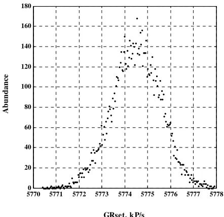
[image:6.595.311.538.120.543.2]57700 5771 5772 5773 5774 5775 5776 5777 5778 20
40 60 80 100 120 140 160 180
GRset, kP/s
A
b
un
da
nc
e
Figure 10. Histogram of the output pulse generation rate with uniform PDF (GRset = 6 MP/s, GRExp = 5.774492 MP/s,
STD = 1.056 kP/s, N.S. = 104, 200 bins).
IP cores have clock latencies. Therefore, calculation process performed by the hardware generates random time intervals every 30-digitization period. The maxi- mum random time interval generation rate is limited to the values, which are smaller than 7 million samples per second. As the inter event dead time is a source of error, the maximum possible output pulse generation rate with an error less than 5 per cent was measured equal to 6 MP/s for one channel architecture. Since there is a single random number generator in the design, while there are eight output channels, random pulse generation rate can- not exceed more than 750 kP/s for each channel. This is the only possible limitation imposed by multichannel implementation.
FPGAs support multiple digital voltage standards. The output pulses shown in Figure 2 are either 2.5-V LVTTL or 1.2-V LVTTL standards depending on the chosen IO pin of the device. This is an advantage, which makes the design easily compatible with different digital voltage standards. Another important capability of FPGAs is the possibility of upgrading and revising of the design based on programming. The unique features of the technology make the system as a cost-effective tool for future in- depth research into the certification of multichannel sto- chastic detection systems by non-radioactive experiments.
4. Conclusion
Random pulse generator is one of important apparatuses in nuclear experiments. A range of equipment with dif- ferent features has been invented previously. An efficient multichannel random pulse generator, which is low cost due to implementation on a single FPGA device, was
presented. The simple architecture can be easily modified to be compatible with any especial experimental case stu- dy. Uniform and Poisson PDFs were tested in experiment. Average output pulse generation, output pulse width, and PDF of each channel can be adjusted by the computer through USB cable connection. Detailed useful experi- mental test results were shown in Table 1. The time re- solution is 5 ns, minimum pulse width is 10 ns, and the minimum inter event dead time is 15 ns for the design.
The maximum tested in experiment output pulse gen- eration rate is 6 MP/s with a relative error less than 5 per- cent. This error is due to the dead time effects of the equipment. As the generator is capable of generating pul- ses with different statistical characteristics, this is a use- ful flexible instrument to handle the complex experimen- tal tests on nuclear detection systems especially for those are multichannel types. The core of the random pulse ge- nerator is the random number generator. This is perform- ed by LFSR (a pseudorandom number generator) techni- que which is the only source of random number genera- tion for all output channels. Useful scientific papers have been published on random number generators based on FPGAs. The architecture can be facilitated with modern techniques to be more efficient. Multiple random number generators in the design can make the output pulse gen- eration speedier for multichannel structure as well. Fu- ture experimental tests on nuclear detection systems can gain useful knowledge of the design to become more pro- ficient as much as FPGA technology allows.
REFERENCES
[1] M. Wiernik, “Normal and Random Pulse Generators for the Correction of Dead-Time Losses in Nuclear Spectro- metry,” Nuclear Instruments and Methods, Vol. 96, No. 2, 1971, pp. 325-329.
http://dx.doi.org/10.1016/0029-554X(71)90324-7 [2] J. J. Gostely and P. Lerch, “Counting Signals from Radio-
activity-Measurement Systems,” Nuclear Instruments and Methods in Physics Research Section A: Accelerators,
Spectrometers, Detectors and Associated Equipment, Vol. 290, No. 2-3, 1990, pp. 521-528.
http://dx.doi.org/10.1016/0168-9002(90)90572-N
[3] J. Gál, B. György and J. Pálvölgyi, “A Random Tail Pulse Generator for Simulation of Nuclear Radiation Detector Signals,” Nuclear Instruments and Methods, Vol. 171, No. 2, 1980, pp. 401-406.
[4] P. C. Johns and M. J. Yaffe, “Correction of Pulse-Height Spectra for Peak Pileup Effects Using Periodic and Ran- dom Pulse Generators,” Nuclear Instruments and Meth- ods in Physics Research Section A: Accelerators, Spec- trometers, Detectors and Associated Equipment, Vol. 255, No. 3, 1987, pp. 559-581.
http://dx.doi.org/10.1016/0168-9002(87)91227-7
[image:7.595.62.283.83.297.2]Nuclear Instruments and Methods in Physics Research Section A: Accelerators, Spectrometers, Detectors and As- sociated Equipment, Vol. 276, No. 3, 1989, pp. 573-576. http://dx.doi.org/10.1016/0168-9002(89)90585-8
[6] P. Dajing, “A Uniform Amplitude Spectrum Generator for Test of the Maximum Effective Pulse Rate of MCAs,”
Nuclear Instruments and Methods in Physics Research Section A: Accelerators, Spectrometers, Detectors and Associated Equipment, Vol. 251, No. 3, 1986, pp. 531- 535. http://dx.doi.org/10.1016/0168-9002(86)90648-0 [7] D. Ponikvar, “Generator of Pseudo Random Pulses,” Nu-
clear Instruments and Methods in Physics Research Sec- tion B: Beam Interactions with Materials and Atoms, Vol. 83, No. 1-2, 1993, pp. 295-299.
http://dx.doi.org/10.1016/0168-583X(93)95941-W [8] R. E. Abdel-Aal, “A Versatile Programmable CAMAC Ran-
dom Pulse Generator,” Nuclear Instruments and Methods in Physics Research Section A: Accelerators, Spectrome-ters, Detectors and Associated Equipment, Vol. 309, No. 1-2, 1991, pp. 331-338.
[9] F. N. Ferrucci, C. A. Verrastro, G. E. Ríos and D. Estryk, “FPGA-Based Random Pulse Generator for Emulation of a Neutron Detector System in a Nuclear Reactor,” IEEE VII Southern Conference on Programmable Logic (SPL), Cordoba, 2011, pp. 103-108.
http://dx.doi.org/10.1109/SPL.2011.5782633
[10] J. Lauch and H. U. Nachbar, “Random Pulse Generator with a Uniformly Distributed Amplitude Spectrum,” Nu-
clear Instruments and Methods in Physics Research Sec-
tion A: Accelerators, Spectrometers, Detectors and Asso- ciated Equipment, Vol. 267, No. 1, 1988, pp. 177-182. http://dx.doi.org/10.1016/0168-9002(88)90645-6
[11] W. B. Divon and B. Rozen, “A Random Pulse Generator,”
Nuclear Instruments and Methods, Vol. 39, No. 1, 1966, pp. 77-87.
http://dx.doi.org/10.1016/0029-554X(66)90046-2
[12] G. White, “The Generation of Random-Time Pulses at an Accurately Known Mean Rate and Having A Nearly Per- fect Poisson Distribution,” Journal of Scientific Instru- ments, Vol. 41, No. 6, 1964, pp. 361-364.
http://dx.doi.org/10.1088/0950-7671/41/6/302
[13] G. F. Knoll, “Radiation Detection and Measurement,” John Wiley & Sons, Inc., 1999.
[14] C. H. Vincent, “Random Pulse Trains Their Measurement and Statistical Properties,” Peter Peregrinus Ltd., 1973. [15] IEEE 754, “Standard for Binary Floating-Point Arithme-
tic,” 1985.
[16] ALTERA Corporation, “Nios II Software Developer’s Handbook Version 11.1,” 2011. www.altera.com
[17] ALTERA Corporation, “QUARTUS II Handbook Ver- sion 11.1,” 2011. www.altera.com
[18] ALTERA Corporation, “STRATIX III Device Handbook,” 2011. www.altera.com
[19] ALTERA Corporation, “STRATIX III DSP Development Kit Reference Manual,” 2008. www.altera.com
Nomenclature
P/s: Pulse per second.STD
21
1 1
n
i
x x
n
CDF: Cumulative distribution function. : Standard deviation.
FIFO: First-in, First-out.
FPGA: Field programmable gate array. t: Time variable.
GRExp: Measured output mean generation rate. tPoisson: Time interval between two successive random
pulses with Poisson PDF. GRset: Selected output mean generation rate.
IEEE: The institute of electrical and electronics engi-
neers. tform PDF. Umax: Maximum time interval between pulses with
uni-IP: Intellectual property. tUniform: Time interval between two successive random
pulses with uniform PDF. n: Average number of random pulses per second.
NPoisson: Number of digitization periods between two
successive random pulses with Poisson PDF (an integer number).
:
U Average time interval between pulses with uni- form PDF.
t
T: Digitization period.
N.S.: Number of samples. TTL: Transistor-transistor logic.
NUniform: Number of digitization periods between two
successive random pulses with uniform PDF (an integer number).
VHDL: Virtual hardware description language. ζ: Normalized uniform random variable (0 ≤ ζ ≤ 1).
Exp
GR
: Output mean generation shift fromGRset. PDF: Probability distribution function.