EMERGENCY VEHICLE DETECTION SYSTEM USING RF MODULE AND
ULTRASONIC SENSOR
CHESTI ALTAFF HUSSAIN
1CH.JEEVAN KISHORE
2M. SAI TIRUMALESH
3M.DEDEEPYA
4Asst. Professor
1, Dept of Electronics and Communication Engineering, Bapatla, Andhra Pradesh, India
UG Student
234, Dept of Electronics and Communication Engineering, Bapatla Engineering College, Bapatla, Andhra
Pradesh, India.
---***---Abstract
---
This paper proposes an intelligent lane clearance and collision avoidance system as a prototype, which avoids delay and crashing of ERVs (EMERGENCY RESPONSE VEHICLE) and provides greatest security to the ERVs. Here ultrasonic sensor is used to continuously track for any obstacle. If the obstacle is detected then microcontroller will continuously compare the distance given by the ultrasonic sensor. If the obstacle is closer to the ERVs then a control signal is sent to the nearby vehicle and its speed is controlled by the microcontroller placed in the obstacle. The lane clearance is done based on the warning signals given to the nearby vehicles. A warning display unit and sound producing unit is placed on the dashboard of the vehicles. Here RF transmitter and receiver are used to communicate between the two microcontrollers.Keywords
---
Ultrasonic sensor, ATMEL 89S52, RF-434Mhz Tx and Rx, IR sensor.I.INTRODUCTION
There are several advanced technology and innovations are available for vehicle safety. Even though there are advanced technological innovations for vehicle safety, the growth in number of accidents and increase in death rate due to delay is continuously increasing. And these accidents are due to collision or intersectional accidents and due to delay in reaching the accident spots and to hospitals. Delay of ERVs is because of vehicles not giving side this is because of mainly two reasons. They are car’s audio and sound isolation may prevent a driver from hearing an ERV siren. Collision of vehicles occurs due to mistakes done by driver and intersectional accidents are caused due to bad weather conditions and over-speeding. Hence, to overcome these mistakes an intelligence collision avoidance and lane clearance system is proposed. Only sports cars and other luxury vehicles consist of antilock
brake system, speed sensor, and other automatic systems. But these cars are not affordable by everyone. So, this system is developed which can be implemented in every vehicle.
This system consists of sensors that are placed in the
ERV and warning systems are placed within the vehicles which provide warning to the driver about the approaching of ERVs. There is a two level warning system for lane clearance. The warning signals are issued by the ERV driver. It is done by using the selection buttons mounted on the dashboard of the ERV. The warning signal is displayed on the LCD screen and also a sound-producing unit is mounted on the dashboard of the vehicle produces maximum sound which alerts the driver. It helps in the cases when driver fails to respond to the warning displayed on the LCD screen. And coming to collision avoidance the ultrasonic sensor will measure the distance in reference to the preceding car. If the distance measured is less than the permissible limits then a control signal is sent to the nearby vehicle microcontroller then the speed of the vehicle is limited. A good example of the system is how it works when an ERV driver is about to change lanes and there is an obstacle in his blind spot. The sensor will detect that obstacle, calculates the distance and control signal is given to the vehicle he start turning his car, and prevent him from getting into serious accident.Rx for issuing and receiving of warning signals to the vehicles nearby to ERVs. This project effectively avoids collision of ERVs with other vehicles and decrease the delay time in significant manner.
II.FUNCTIONAL DESCRIPTION
The functional block diagram of the system for both
transmitter and receiver parts are shown in the fig 1 and fig 2.This prototype consists of different blocks and there function is explained as follows:
Fig1.Functional Block diagram in ERV
Based on the selection of buttons the micro controller transmits corresponding signal through RF-Tx, and it is received by the RF-Rx. The ultrasonic sensor measures the distance and continuously sends the data to the microcontroller.
Fig. 2. Block diagram for Non-Emergency Vehicles
On receiving of signals the corresponding warning signal is displayed on the LCD screen, correspondingly the sound producing unit produces the sound. Here the DC motor driver is controlled by the microcontroller in the ERV.
A.
ATMEL 89S52
The ATMEL 89S52 is a low-power and
high-performance 8-bit microcontroller which is designed using CMOS technology with 8K bytes of in-system programmable Flash memory. Atmel designed this IC using high-density nonvolatile memory technology and is compatible with the Industry standard 80C51 instruction set and pin out. The on-chip Flash memory in this IC allows the program memory to be reprogrammed in-system or by a conventional nonvolatile memory programmer. The Atmel AT89S52 is a powerful microcontroller which provides a highly-flexible and cost-effective solution to many embedded control applications.The AT89S52 has the following standard features: 8K bytes of Flash memory, 256 bytes of RAM, Watchdog timer,32 I/O lines, two data pointers, three 16-bit timer/counters, a six-vector two-level interrupt architecture, a full duplex serial port, on-chip oscillator, and clock circuitry. In addition to this it is designed with static logic for operation down to zero frequency and it also supports two software selectable power saving modes in which it can be operated. During Idle Mode the CPU stops working while allowing the RAM, serial port, timers/counters and interrupt system to continue their functioning. And in the Power-down mode the RAM contents are saved but it freezes the oscillator, disabling all other chip functions until the next interrupt or hardware reset.
B.
Ultrasonic sensor
Ultrasonic ranging sensor HC - SR04 is used for non-contact measurement function up to 2cm-400cm, the ranging accuracy can be equivalent to 3mm. The module includes ultrasonic transmitter, receiver and control circuit within a unit.
Micro controller
(ATMEL 89S52)
Power supply
Selection buttons
RF-Tx
Distance measurement
(Ultrasonic sensor)
Micro controller
(ATMEL 89S52)
Power supply
RF-Rx
Display
(LCD)
Buzzer
Dc Motor driver
Motor
IR sensor
The module consists of 4 pins. They are VCC of 5v, input trigger pulse, output echo pulse, and ground. The electric parameter of ultrasonic sensor is, its working voltage is 5v DC, its operating frequency is 40 KHz. The triggered input signal is 10us TTL pulse.
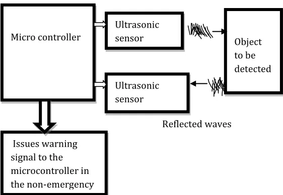
Ultrasonic sensor works on the piezoelectric effect principle. The block diagram shown in figure 3 depicts the working principle of sensor.
Burst of Ultrasonic Waves
[image:3.612.29.310.278.472.2]Reflected waves
Fig. 3.Working principle of ultrasonic sensor
The basic principle of work:
(1) Using IO trigger for at least 10us high level signal
(2) The Module automatically sends eight 40 kHz and detect whether there is a pulse signal back.
(3) IF the signal reflects back, through high level, time of high output IO duration is the time from sending ultrasonic to returning. Test distance = (velocity of sound x high level pulse time/2).where velocity of sound in air=340m/s.
Once the obstacle is detected, the reflected waves (echo) are sensed by the receiver and analyzed by the microcontroller. If the distance is not in the safe limit, then the microcontroller in the ERV issues a warning signal to
the microcontroller in the non-emergency vehicle. When the received echo is faded, then the next trigger pulse is sent and the total time period is called cycle period. The cycle period must not be below 50ms for this corresponding sensor HC-SR04.
C.
RF-434Mhz Tx and Rx modules.
This prototype utilizes the RF module (Tx/Rx) which is used to drive an output from a faraway place. The RF module uses radio frequency to send signals. These signals are transmitted at a particular frequency and a baud rate based on requirement. The corresponding Radio frequency range varies from 30 kHz & 300 GHz. In the RF system, the digital data which is transmitted is represented as the variations in the amplitude of the carrier wave. This kind of modulation used here is known as Amplitude Shift Keying (ASK).
Transmission through Radio Frequency is better than Infrared because of many reasons. Signals through RF can travel larger distances by making it suitable for long range applications. While IR is mostly operated in line-of sight mode, RF signals can travel even when there is an obstruction between transmitter & receiver. Next, RF is more strong and reliable for transmission. RF communication uses a particular frequency for applications.
The transmitter/receiver (Tx/Rx) pair operates at a frequency of 434 MHz The RF transmitter receives serial data and transmits it wirelessly through RF through its antenna connected at pin4. The parallel to serial data conversion is done the Encoder. The transmission rate is of 1Kbps - 10Kbps.The transmitted data is received by an RF receiver operating at the same frequency as that of the transmitter and it is decoded. The RF module is often used along with a pair of encoder and decoder. HT12E-HT12D, HT640-HT648, etc. are some commonly used encoder and decoder pair ICs for different applications.
D.
Infrared sensor
Infrared sensor Infrared sensor is an electronic device which is used for lane detection. It consists of an emitter (infrared LED) and a receiver (photo diode). The light emitted by the LED is collected by the photo diode. If there is any black surface, it absorbs the light emitted by LED and receiver cannot sense light. If the surface is white in Micro controller
Ultrasonic sensor Ultrasonic
sensor Object
to be detected
color, then the light emitted by IR LED gets reflected and it will be sensed by photo diode situated in the module.
Fig.4. Infrared sensor
The output of the sensor is given to the comparator inverting terminal as the input, and compares this signal with reference voltage set by potentiometer. So, when the emitter pair is on the reflecting surface, the sensor will be on. Hence, brightness of the object can be measured by using this type of sensor. This sensor is useful in case of lane line tracking.
III. WORKING
The ERV consists of ultrasonic sensor and infrared sensors. Ultrasonic sensor and IR sensors are placed outside of the vehicle in the front and backside. Initially the nearby vehicles are sensed by the IR sensors, and then RF transmitter transmits the 2nd level of warning signal. And if
the vehicles are very distant from the ERV the 1st warning
signal is displayed. This process is for lane clearance. Similarly for collision avoidance ultrasonic sensor is used to measure the distance. If the vehicle crosses the permissible limits then a warning signal is sent to the non-emergency vehicle, it is displayed in the LCD screen and speed is controlled.
IV.SOFTWARE IMPLEMENTATION
Keil µvision3 IDE is the software used to program
microcontrollers used in the designing of the prototype. The microcontroller used in our system is AT89S52.It supports in-system programming, and the programming interface is called serial programming interface where the code is transferred from PC to microcontroller. To dump the he code from keil IDE into microcontroller the software used is flash magic through SPI interface.
No
Yes
No
Yes
Fig.5. Flow chart regarding to the prototype working.
V.CONCLUSION
The proposed system is designed as a prototype to display the working of the system. By the use of IR sensors the variation in warning signals is given to the vehicles. Similarly the ultrasonic sensor is used to avoid the collision between ERVs and non-ERV.
By using this proposed system the deaths due to delay and ERV collisions can be decreased and the implementation of the system is also very easy and it can be implemented at a low cost. The alert mechanism used in system will facilitate the ERV driver at any unusual movement of the vehicle. It can be integrated with the already existing systems.
Start
Initialization
Read ultrasonic sensor
If distance< fixed value
Emit RF signal
Check the IR signal
Display 2nd warning signal and lower the speed
Display 1st warning signal
REFERENCES:
[1] Triveni Shinde and B. V. Pawar, ―Car anti-collision and intercommunication system using communication protocol‖, International journal of engineering sciences and research technology ISSN:2319-7064,Volume-2, No-6, pp.187-191, June-2013
[2] S. Saravanan, T. Kavitha, ―Vehicle navigation and obstacle detection system using RFID and GSM‖, Journal of Theoretical and Applied Information Technology, Vol. 38,No-2, pp.206-209, 30th April 2012
[3] N. S. Vaidya and A. V .Nikalje, ―Arm based invention in car mobility and atomization‖, International journal of engineering and innovative technologyISSN: 2277-3754, Volume-3, No-5, pp.238-244, november-2013
[4] Vivek agarwal, N. Venkata Murali, and C. Chandramouli, ―A Cost-Effective Ultrasonic Sensor-Based Driver- Assistance System for Congested Traffic Conditions‖, IEEE Trans. Intell. Transp. Syst., vol.10, NO.3, pp. 486498, Sep -2009
[5] Shival Dubey and Abdul Wahid Ansari, ―Design and development of vehicle anti-collision system using electromagnet and ultrasonic sensors‖, International Journal on Theoretical and Applied Research in Mechanical Engineering ISSN: 2319 – 3182, Volume-2, No-1, pp.80-83, Jan-2013
[6] Anusha c, Dr. P. Venkataratnam―Collision Control and collision avoidance using ultrasonic sensor‖, International Journal of Current Engineering and Scientific Research ISSN: 2393-8374, VOLUME-2, ISSUE-7, 2015
[7] Mitchell, W. L. Traffic light control for Emergency Vehicles, US 4443783, 1984.
[8] Obeck C. J. Traffic signal control for Emergency Vehicles, US 5014052, 1991.
[9] Rose C. R. et all. Emergency vehicle detection system, US 5894279, 1999
[10] Shruthi, K R, and K Vinodha. 2012. “Priority based traffic lights controller.” International journal of Electronics signals and systems (IJESS) 1(4): 58–61.
[11] Singh, H.K Kumar and H Kaur. 2012. “Intelligent traffic lights based on RFID.” International Journal of Computing and Business Research.
[12] Talluri, P, and A Kumar M. 2013. “Intelligent Traffic system which responds to Emergencies.” International Journal of Engineering Trends and Technology (IJETT) 4(April): 1132–33.
[13] Vicente Milanes, Jorge Villagra, Jorge Godoy, Javier Simo, Joshue Perez, and Enrique Onieva, “An Intelligent V2IBased Traffic Management System”, IEEE Transaction on Intelligent Transportation System, Vol. 13, No. 1, March 2012.s
[14] Ganesh Khekare, Apeksha Sakhare, “Intelligent Traffic System for VANET: A Survey”, International Journal of Advanced Computer Research, Volume-2 Number-4 Issue-6 Dec 2012.
[15] Sanjay S. Dorle, Pratima L. Patel, “Design Approach for Dynamic Traffic Control System Based on Radio Propagation Model in VANET”, International Journal of Computer Science and Network, Vol 2, Issue 1, 2013.
[16] Ms. Promila Sinhmar, “Intelligent Traffic Light and Density Control using IR Sensors and Microcontroller”, International Journal of Advanced Technology & Engineering Research (IJATER) ISSN No: 2250-3536 VOLUME 2, ISSUE 2, March 2012.
[17] Hosna Tashakkori Hashemi and Siavash Khorsandi, “Load Balanced VANET Routing in City Environments”, Vehicular Technology Conference (VTC Spring), 2012
[18] Peyman Babaei, “Vehicles tracking and classification using traffic zones in a hybrid scheme for intersection traffic management by smart Road Side Units”, 2010
[19] Kartik Pandit, Ghosal, D., Zhang, H.M., Chen-Nee Chuah, “Adaptive Traffic Signal Control With Vehicular Ad hoc Networks”, IEEE Transactions on Vehicular Technology, Volume: 62 , Issue: 4 May 2013.