AERODYNAMIC PERFORMANCE ANALYSIS OF A CO-FLOW JET AEROFOIL
USING CFD
Sridhar Ethiraj
11
Student, School of Mechanical and Building Science, VIT University Chennai, Tamilnadu, India
---***---Abstract -
The research demonstrates the new performance method for co-flow jet Aerofoils using discrete jets. Our aim is to use a flow control method, which would be incorporated in the wing to attain the same required value of lift, thus there by relieving off the additional penalty in terms of movable control surfaces. The intention is to achieve this by implementing Co flow jet control. By injecting the high pressurized air towards the streamline of the Aerofoil from leading edge and sucks the same amount of air in trailing edge using pumps. By achieving this, there is a high kinetic energy across the wing surface and by translating a major portion of the suction surface downwards thus zero net mass flux will occur across the Aerofoil section. This enhances a lateral transport of energy from the jet to the main flow, thereby establishing a circulation control which in turn increases the lift produced. In this Research a CFD analysis is done on a wing which has Co flow jet control implemented in it. Thus this implementation is changing the aerofoil series and gives the comparative results of the baseline and Co flow jet aerofoil. CFD analysis is done using the Reynolds averaged 3d compressible naiver-stokes (rans) equations as the governing equations. The analysis is done for various angle of attack this will shows high lift and stall angle at higher angle of attack, with decrease the drag force.Key Words:
Aerodynamic forces, Non-planar wings, Mach number, Angle of attack, Induced drag, L/D ratio.1.
INTRODUCTION
The wing is the major lift producing part in an aircraft, but the usage of wing alone will not produce the required lift necessary for take-off or landing hence we use the additional high lift devices. The configuration of the wing, divided into three surfaces, as slat, mid-wing and the flap is called the trap wing configuration, this is currently used for producing the necessary lift. This configuration calls for a separate avionics, and auxiliary control surfaces which act as an additional penalty on aircraft. Flow control (FC) is the most promising route to break through the conventional aerodynamic design limit and bring dramatic performance improvement to aircraft. NASA, Air Force and aerospace industry have recently made great efforts to develop flow control technology. To enhance lift and suppress separation, various flow control techniques have been used, including rotating cylinder at leading and trailing edge, circulation control using tangential blowing
at leading edge and trailing edge, multi element Aerofoil, pulsed jet separation control, etc. When a flow control technique is developed, there may be three issues needed to be considered.
• Effectiveness • Energy Efficient • Easy Implementation
1.1 Co- Flow Jet Aerofoil
Fig -1: Row of Co-Flow Jets
2.
OBJECTIVE
The purpose of this research is to apply the co-flow jet flow control method to a typical thin aerofoil in order to demonstrate its performance enhancement capabilities. This work included the design and manufacturing of a thin co-flow jet aerofoil with adjustable slot sizes. CFD analysis was performed for a baseline aerofoil and for the co-flow jet aerofoil with two different momentum coefficients, Cµ= 0.05andCµ= 0.1.Cµ is a dimensionless parameter.
3.
METHODOLOGY
3.1.
Design
3.1.1. Co-flow jet Aerofoil
A thin cambered aerofoil was chosen for this research to demonstrate that Co-Flow Jet implementation is possible for any Aerofoil thickness. Previous studies of wind tunnel experiments and CFD analysis have been done using a NACA 0025 aerofoil, which is thicker and symmetric. The NACA 63-015 Aerofoil was chosen in this project for the baseline shape and as a guide for the translation of the suction surface to become a Co-Flow Jet Aerofoil. The Aerofoil has a 1m chord length and a 2m span. The injection and suction slot heights are measured as the distance of the openings normal to the upper curved surface of the baseline Aerofoil. The thinner injection slot has a lower mass flow rate and requires less power from the compressor bleed. The suction slot is larger so that the same mass flow expended by the injection slot can be removed by the suction slot without choking, due to the lower static pressure achieved by the vacuum. The form is NACA 63-015-INJ SUC, where INJ and SUC are replaced by the injection and suction slot heights as a percentage of the chord. The resulting aerofoil is the Co-Flow Jet 63-015 -080-142. The injection slot should be located as close to the leading edge as possible but still downstream of the suction peak on the Aerofoil. Description of the aerofoil design includes exterior coordinate generation for baseline and co-flow jet aerofoils, development of interior cavities required for the Co-Flow Jet Aerofoil.
3.1.2. External Geometry of an Aerofoils
Coordinate data was used from a NACA 63-015 aerofoil as the baseline shape of the co-flow jet aerofoil. The
coordinates were then used to generate 2- and 3-dimensional models using CATIA V5R20 3-D modelling software. Each number in a NACA 6-digit series aerofoil has a specific function to determine the resulting shape. The wing shape begins with a mean line which is then offset with a thickness distribution function for both the upper and lower surfaces of the aerofoil. The resulting coordinates give the shape of the wing section.
3.1.3. Internal Geometry of an Aerofoil
With the exterior profiles of the baseline and co-flow jet aerofoil complete, the internal ducting for the injection and suction cavities were created. The shapes of the interior curves were driven by three factors: the minimum area required for flow without being choked, internal aerodynamic characteristics, and ease of machining. Since air will be supplied to and removed from the aerofoil to create the co-flow jet, the internal cavities needed to have large enough areas so that there would be no choked flow and the mass flow rates could be controlled for various tests. The internal features should include aerodynamic shapes for the most effective use of high pressure air to generate the jet. Throughout the design of the model, manufacturing capabilities were considered to ensure that the final aerofoil would be easy to machine without complicated and costly features.
In the injection cavity, the pressure will increase as Cµ increases. Also, the increased mass will require higher pressure. The pressure can be regulated by controlling the amount of flow entering the cavity from the air delivery system. The minimum 2-D area for the injection cavity is therefore not as critical as the minimum area for the suction cavity, because the pressure will increase as mass flow increases on the injection side. The minimum area was found to (3.222 x 10⁻⁴m2) for the injection cavity.
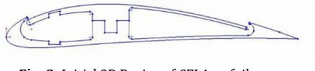
Fig -2: Initial 2D Design of CFJ Aerofoil
[image:2.595.321.546.534.585.2]in CATIA V5R20 using splines that followed the desired internal shape for the cavities.
An Aluminium foam and suction supports are shown in the injection cavity and suction cavity respectively. They are transparent so that the fasteners can be seen. For the adjustable slot size aerofoil, shims will also be placed under each suction support to assist in maintaining the desired suction slot distance. Near the trailing edge, another cut was made so that the upper lip of the suction opening could be removed.
Fig-3: Final 2D Design of CFJ Aerofoil
Fig-4: Aluminium Foil for Speed Control
Fig-5: Final 3D Design of CFJ Aerofoil
3.1.4. End plates
To close the cavities off at the ends of the aerofoil and to provide a connection to the force balance and air systems, end plates were added to the model. A 0.25 thick end plate was placed at each end of the model. One end has a solid end plate and one has an end plate with a connection to the force balance and an opening for a manifold connection to the vacuum system.
Fig-6: End plates to cover an Aerofoil
3.2.
Meshing
3.2.1. Meshing of Baseline and CFJ Aerofoil
For any CFD code simulation, the first task is to generate a mesh within the flow field. Sometimes the space will contain the geometry of a solid body that will interact with the flow. In the case of this research, the free stream flow field contains baseline and co-flow jet aerofoils. If the solution space can be reduced to a single point, then the mesh within that space is considered simply connected. The mesh size at wall boundaries is much finer than further out in the flow field.
If a mesh is very large, CPU time can be reduced by splitting the mesh into sections and running them simultaneously using an MPI (Message Passing Interface parallel computing process. The mesh that fits the actual solution space is often built around complicated geometries, depending on the application. The position of each node is assigned a real coordinate in Cartesian space. This is referred to as the physical domain and has values for each x, y, and z coordinate.
Fig-7: 3D Meshing of Baseline Aerofoil
Fig- 8: 3D meshing of CFJ Aerofoil
3.3.
Boundary Conditions
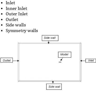
Once the meshing is done, the next step is to assign the boundary conditions for analysis the performance of an aircraft. The various conditions considered here are,
• Inlet • Inner Inlet • Outer Inlet • Outlet • Side walls • Symmetry walls
Fig- 9: Boundary Conditions
3.4.
Analysis of an Aerofoil
3.4.1. Solver Controls
[image:4.595.60.263.304.497.2]After generating mesh it was feed to a solver to calculate the flow properties. Here the solver used was a fluent. Ansys fluent is a state-of-the-art computer program for modelling fluid flow, heat transfer, and chemical reactions in complex geometries. Ansys Fluent uses a client/server architecture, which allows it to run as separate simultaneous processes on client desktop workstations and powerful computer servers.
Table -1: Solver Controls
Baseline
Aerofoil
CFJ Aerofoil
Advance scheme High Resolution
High Resolution Turbulence First Order First Order
Numeric
Min. Iteration 1 1
Max. Iteration 1000 1000
Timescale Control Physical Time scale
Physical Time scale
Physical Time scale 2s 2s
This architecture allows for efficient execution, interactive control, and complete flexibility between different types of machines or operating systems. Ansys Fluent provides complete mesh flexibility, including the ability to solve the flow problems using unstructured meshes that can be generated about complex geometries with relative ease. Supported mesh types include2D triangular/quadrilateral, 3D tetrahedral/ hexahedral/ pyramid/ wedge/ polyhedral, and mixed (hybrid) meshes. Ansys fluent also allows to refine or coarsen the mesh based on the flow solution.
4.
RESULTS AND DISCUSSION
Thus the CFD analysis of baseline and CFJ aerofoil are discussed below and the comparative results are generated, the Analysing of the Aerofoil is shown as
Fig- 10: Analysing with Solver Control
Fig- 11: Pressure Contour at 0, 4, 8, 12, 16 degree AOA
Fig-12: Velocity Contour at 0, 4, 8, 12, 16 degree AOA
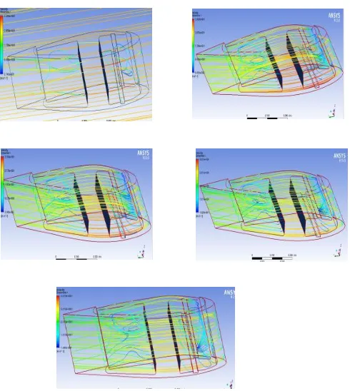
Fig-13: Surface Flow at 0, 4, 8, 12, 16 degree AOA
4.2. Co-Flow Jet Aerofoil
Fig-14: Pressure Contour at 0, 4, 8, 12, 16 degree AOA
Fig-16: Surface Flow at 0, 4, 8, 12, 16 degree AOA
4.3.
Coefficient of lift for all angles
[image:6.595.36.281.96.370.2]The coefficient of lift versus angle of attack for the Base aerofoil and CFJ aerofoil model studied in the present investigation are shown. From the below table it is observed that the lift increases with increase in angle of attack to a maximum value and there by decreases with further increase in angle of attack. The maximum values of the lift coefficient occur at an angle of attack of 12 degrees for Base aerofoil and angle of attack of 14 degrees for CFJ-wing.
Table -2: Co-efficient of Lift
Fig-17: AOA vs CL
4.4.
Coefficient of drag for all angles
The drag coefficients of all the Aerofoil is shown in below table. From the below graph it is observed that the drag coefficient for the AEROFOIL model measured under all the configurations under this study shows an increasing trend with angle of attack. The drag increases slowly with increase in angle of attack to a certain value and then it increases rapidly with further increase in angle of attack. The rapid increase in drag coefficient, which occurs at higher values of angle of attack, is probably due to the increasing region of separated flow over the wing surface,
which creates a large pressure drag.
Table -3: Co-efficient of Drag
Fig-18: AOA vs C
D4.5. C
L
/C
DRatio for all angle
The co-efficient of lift/co-efficient of drag ratio is the outcome of the observations made in the two preceding sections. It is observed from the below figure that the co-efficient of lift/co-co-efficient of drag ratio for all the configurations considered increases with an angle of attack to its maximum value and thereby it decreases with further increase in angle of attack.
Table -4:
C
L/C
DRatio
SN.NO Angle of
Attack Baseline Aerofoil CFJ Aerofoil
1 0 13.09 15.26
2 4 15.85 16.2
3 8 12.65 13.15
4 12 11.23 11.043
[image:6.595.313.561.298.431.2]Fig-19: AOA vs CL/CDRatio
5.
CONCLUSION
From the drag coefficient and lift coefficient graph it is clearly shown that using co-flow jet aerofoil will increase lift force and reduce drag force. With increasing the thrust.
This co-flow jet aerofoil design is capable to reduce drag force and convert streamline vortices to additional thrust which will save cost by reducing the usage of fuel, noise level reduction and increase the efficiency of the aircraft engine.
The analysis results will shows 25-30 percent reduction in drag and 10-20 percent increase in lift coefficient by using these configuration for angle of attack of 12 degree.
The analysis results will increase in stall angle at an angle of attack of 140-160, when compared to results of previous studies.
This investigation provides a better understanding for the co-flow jet aerofoil and its inclusion to the aerofoil of aircraft wing model.
REFERENCES
[1] NASA, AIAA CFD High Lift Workshop (http: //hiliftpw.larc.nasa.gov.).
[2] Ge-Cheng Zha, Bruce F. Carroll, Craig D. Paxton, Clark A. Conley and Adam Wells, High Performance Aerofoil Using Co-Flow Jet Flow Control, AIAA Paper 2005-1260.
[3] Ge-Cheng Zha, Wei GAO and Craig Paxton, Numerical Simulation of Co-Flow Jet Aerofoil Flows, AIAAPaper2006-1060, 44th AIAA Aerospace Sciences Meeting and Exhibit, January 2006, Reno, Nevada.
[4] Ge-Cheng Zha,Wei Gao,Craig D. Paxton and Alexis Palewicz, Numerical Investigations of Co-Flow Jet Aerofoil with and without Suction, AIAA Paper 2006-1061, 44th AIAA Aerospace Sciences Meeting and Exhibit, January 2006, Reno, Nevada.
[5] Bertrand P. E. Dano, Gecheng Zha and Michael Castillo, Experimental Study of Co-Flow Jet Aerofoil Performance Enhancement Using Discrete Jets, AIAA paper 2011-941, 49th AIAA Aerospace Sciences Meeting including the New Horizons Forum and Aerospace Exposition, January 2011, Orlando, Florida.
[6] Ge-Cheng Zha and Wei Gao, Analysis of Jet Effects on Co-Flow Jet Aerofoil Performance with Integrated Propulsion System, AIAA Paper 2006-0102, 44th AIAA Aerospace Sciences Meeting and Exhibit, January 2006, Reno, Nevada.
[7] G. Zha, J. J. Dussling, S. Aspe, N. R. Heinz and D. J. Martinez, Quiet Ultra-Efficient Integrated Aircraft Using Co-Flow Jet Flow Control, AIAA Paper 2009-1437, 47th AIAA Aerospace Sciences Meeting Including The New Horizons Forum and Aerospace Exposition, January 2009, Orlando, Florida.
[8] A. J. Wells, Experimental Investigation of An Aerofoil with Co-Flow Jet Flow Control, Master thesis, University of Florida, 2005.
[9] Somajyoti Majumder, Steve Scheding, Hugh Durrant-Whyte., Sensor fusion and map building for underwater navigation, Australian Centre for Field Robotics(ACFR), University of Sydney(2006).