© 2017, IRJET | Impact Factor value: 5.181 | ISO 9001:2008 Certified Journal | Page 2106
Load Frequency Control of Single Area Power System Using JAYA
Algorithm
Vikas Singh
1, Alok Kumar Singh
2, Vibhor Chauhan
3,Dr. Alok Kumar Bharadwaj
41
M.Tech. Scholar, Jaipur Institute of Technology, Jaipur, Rajasthan
2,3Associate Professor, Jaipur Institute of Technology, Jaipur, Rajasthan
4
Professor, Bengal College of Engineering and Technology, Durgapur
---***---Abstract -
The constant frequency with reliability of poweris a frame set to drive the enormous industrial and other loads in the power systems of modern time. As per unremitting development of size and complexity of electrical power system with growing interconnections, the problem to maintain the power and frequency free from oscillations has become increasingly severe because of irregular load variations. These undetermined load fluctuations result in mismatch of generated power and load demand for consumption, which finally distresses the quality and reliability of electric power supply. This can be achieved by the load frequency control (LFC) methods. Now a days lot of work is going on to make the systems intelligent so the systems can smartly serve for the betterment of mankind. Even the power sector is also being benefitted by that which is being done by the help of soft computing techniques. This study is an effort in the same direction in which we implemented the JAYA algorithm along with PID controllers to improve the frequency response of single area power system.
Key Words: frequency control, PID controller, transients,
controller parameters, JAYA technique
1. INTRODUCTION
The LFC has crucial role in large size electric power systems with complex interconnections between the areas it has. The main goal of operation of the LFC is to sustain the frequency within the limits of every area in the power system and to keep tie-line power flows within some given or decided limit which is achieved by amending the wattage outputs of the generating alternators to match the inconsistent load demands. In the past few years enormous improvement has been made in the area of load frequency control in interconnected system of power transfer. Designing the LFC with the help of PID controllers makes it prominent and trustworthy, but the main challenge is to decide the parameters of PID controllers.
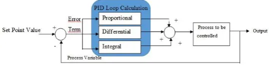
1.1 PID CONTROLLERS
It is well known fact that a proportional integral derivative controller (PID controller) is a standard close loop controller without which the process control in the industries will become a hard nut to crack. A PID controller basically
initiates an action to remove the error between output and reference point, consequently and swiftly, to keep the error trivial within endurable limit. It is an encapsulate unit of proportional, integral and derivative control mode. As it has non-complex structure while it is delivering robust performance is the major reason that it why it is widely used in global applications. The PID controller constraints are set such that closed loop system performance encounters the required specifications and over an extensive range of change input or change in system parameters due to stray effects gives the stout performance and keep the output within required perimeter. Practically, it is almost impossible to have such controller which offers the output with required level and shape of waveform under every internal or external disorder.
1.2 Parameters of PID Controllers
The designing of PID controller actually deals with the scheming of its parameters; i.e. the proportional, integral & derivative coefficient. The process control industries are mostly backing by the PID controller usage in its control strategies.
Fig -1: PID controller in closed loop system
Let,
Kprop = Proportional Gain
Kinti = Integral Gain
Kderiv = Derivative Gain
Then the output of proportional, integral and derivative control mode is given by (Kprop X Error), (Kinti X ∫Error.dt)
and (Kderiv X d/dt(Error))respectively. It shows that the
[image:1.595.309.579.522.587.2]© 2017, IRJET | Impact Factor value: 5.181 | ISO 9001:2008 Certified Journal | Page 2107
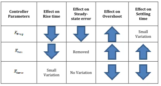
changing. Finally the process is controlled by the pooled [image:2.595.29.289.249.388.2]actions of all three. In simple manner, Proportional mode depends on the current going error, Integral mode depends on the sum of errors of past, and Derivative mode depends on the errors of future based on current rate of change of errors. In a closed loop system (CLS) the variation in the gain parameters shows relevant variations in the characteristics which can be clearly understand by the following observations.
Table -1: Effect on Close loop System Characteristics Due to Gain Parameters of PID Controllers
Controller Parameters
Effect on Rise time
Effect on Steady-state error
Effect on Overshoot
Effect on Settling time
Small Variation
Removed
Small
Variation No Variation
2. TUNING METHODS of PID
The main thing is to be done in the closed loop system with PID controller is to elect the mathematical values of Proportional, Integral and Derivative deciding parameters known as tuning of controller. There are many tuning methods are available to the PID controllers like manual tuning which requires experienced workforce, Ziegler-Nichols method which is said to an aggressive method and online tuning process, Cohen-coon method which is an offline method and only first order process can be determined nicely by it etc., In these methods it is very urgent to get exact transfer function of the system only than it is possible to practice the traditional methods for tuning the PID controller. But in real-world it is very challenging to attain the exact process controlling using traditional tuning methods to tune the PID controllers due to the persistence of high ambiguity in the modelling of practical systems. A precise type of mathematical model is required like first order plus dead time for tuning the process model by traditional methods. Soft computing methods can be the good solution for the problem of precise tuning as these techniques has superiority in solving the complicated and lengthy calculations and even those problems that are mathematically untrack able. The few examples of soft computing methods are Neural Network, Fuzzy Logic, Particle Swarm Optimization etc., But recent JAYA optimization methods has some aids over others. To understand it
3. JAYA TECHNIQUE
The most advantageous thing about this algorithm is its ease of implementation as there is no algorithm-specific variable which are required to be set on which the success of algorithms to converge will depend. The algorithm by itself move closer to best solution avoid failure by avoiding the worst solutions. The algorithm endeavors to become victorious by achieving the best solution and hence it is named as Jaya (a Sanskrit word meaning victory).
To implement and understand JAYA Algorithm following variable terms has to be taken:
f(x) = our objective function which is to be minimized or maximized.
i = number of iteration going on
m = number of design variables assumed (i.e. j=1,2,…,m) n = number of candidate solutions (k=1,2,…,n).
At ith iteration if the best candidate gives the most optimal
value of f(x) i.e. meet our requirement among all the candidate solutions and for the worst candidate we get the worst value of f(x) means it is at farthest from required optimal solution among all the candidate solutions. Now any jth variable whose value at kth iteration is Lj,k,i, is modified according to following equation.
L’j,k,i = Lj,k,i + y1 j,k,i (Lj,best,i- |Lj,k,i|) - y2 j,k,i (Lj,worst,i - |Lj,k,i|)
Here
Lj,best,i = j th variable corresponding to best solution Lj,worst ,i = j th variable corresponding to worst solution L’j,k,i = modified value of Lj,k,i
y1 j,k,i& y2 j,k,i = random numbers during i th iteration for the j
th variable in between [0, 1]
“y1 j,k,i (Lj,best,i- |Lj,k,i|)” is the term which makes the solution to
get closer and closer to optimal solution and the term “- y2 j,k,i
(Lj,worst,i - |Lj,k,i|)” makes the solution to get to sidestep the
worst solution. Finally L’j,k,i will be accepted as our required optimal solution when it gives better function value. At the end of iteration all accepted optimal values will be retained and will serve as input to the next iteration.
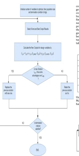
3.1 Workflow in “JAYA” Algorithm
© 2017, IRJET | Impact Factor value: 5.181 | ISO 9001:2008 Certified Journal | Page 2108
Fig -2: Flow chart of JAYA Algorithm to determine tuningparameters for PID controllers
4. SYSTEM SIMULATION & RESULT ANALYSIS
In this the effectiveness of JAYA optimization technique has been scrutinized by applying it in power system for the problems in load frequency control. To accomplish this anticipated method has been applied to determine the controller parameters for load frequency controllability of single area power system. The purpose of load frequency
[image:3.595.30.556.57.647.2]control is to preserve the balance of real power demand and generation in the system at acceptable nominal frequency by control of system frequency. Whenever there is a change in load demand its results in the change in speed of alternator finally led to change in system frequency. The deviation in nominal frequency is amplified and mixed. Finally a proportional command signal is generated which controls the mechanical input to turbine through governor. The governor deeds such that to reestablish the equilibrium between the generation and demand by maintaining the turbine output. The system parameters for the study are tabulated further.
Table -2: System parameters taken for study
S. No. Description Symbol Value
1 Inertia constant H 10
2 Load constant D 0.8
3 Governor time
constant τ
g 0.2
4 Turbine time
constant τt 0.5
5 Droop
coefficient R 0.01
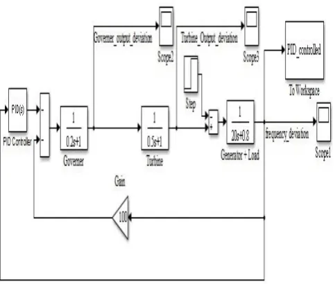
Using these values of various parameters we produced a Matlab Simulink Model of isolated load frequency control has been developed which is shown below in figure
Fig -3: Simulink Model of Isolated Non-reheat Type Power System.
[image:3.595.43.319.84.629.2] [image:3.595.313.562.465.630.2]© 2017, IRJET | Impact Factor value: 5.181 | ISO 9001:2008 Certified Journal | Page 2109
Fig -4: Step Response of generator load frequency withoutsecondary control loop
From the step response graphical representation (figure 4) of the system frequency it is clear that there is inherent steady state error in load frequency response of system for a step input.
There is urgent need of stable feedback control which could reduce the frequency error to zero after a load change. So now to the previous shown isolated system along with PID controller in which parameters are decides by applying JAYA optimization technique and the value of Kinte = 278 and Kprop
= 130 and Kderiv = 381 are obtained. Using these values the
new Matlab Simulink Model has been developed shown in the figure below.
Fig -5: Simulink Model of Isolated Non-reheat Type Power System with JAYA based secondary PID controller
Above shown single area system has been provided with a PID controller for purpose of controlling the deviation of
system frequency. The frequency response of system for a 20% load change controlled with JAYA based PID controller has been shown in figure
Fig -6: Step Response of generator load frequency with JAYA based PID secondary control loop
Dynamic response of the system has been compared in table below for 20% step load change for with and without load frequency controller.
Table -3: Comparison of Dynamic Responses
without
Controller Controller with PID
Steady state error 0.012pu 0
% reduction in Steady
state error 100 %
Peak overshoot -0.0048 -0.0009
% reduction in peak
overshoot 81.25 %
Settling time 6 Sec 3 Sec
% reduction in
settling time 50 %
5. CONCLUSIONS
[image:4.595.38.291.99.275.2] [image:4.595.306.563.145.317.2] [image:4.595.42.284.488.693.2]© 2017, IRJET | Impact Factor value: 5.181 | ISO 9001:2008 Certified Journal | Page 2110
REFERENCES
[1] Armin Ebrahimi Milani and Babak Mozafari, “Genetic Algorithm Based Optimal Load Frequency Control In Two-Area Interconected Power Systems”, Global Journal of Technology and Optimization, pp. 6 – 10, Vol. 2, January 2010.
[2] A.Soundarrajan, Dr.S.Sumathi and C.Sundar, “Particle Swarm Optimization Based LFC and AVR of Autonomous Power Generating System”, IAENG International Journal of Computer Science, pp. 37 – 44, Vol. 1, February 2010. [3] Babak Keyvani Boroujeni, “Two-Area Load Frequency Control Using IP Controller Tuned Based on Tabu Search”, Journal of Basic and Applied Scientific Research, 1(12)2817-2822, 2011.
[4] Ndubisi Samuel .N., “A single area load frequency control: a comparative study based on pi, optimal and fuzzy logic controllers”, American Journal Of Scientific And Industrial Research, pp. 748-754, Vol. - 2(5), 2011. [5] Surya Prakash and S.K. Sinha, “Load frequency control of three area interconnected hydro-thermal reheat power system using artificial intelligence and PI controllers”, International Journal of Engineering, Science and Technology, pp. 23-37, Vol. 4, No. 1, 2011.
[6] Mohamed. M .Ismail and M. A. Mustafa Hassan, “Load Frequency Control Adaptation Using Artificial Intelligent Techniques for One and Two Different Areas Power System”, International Journal of Control, Automation And Systems, pp. 12 – 23, Vol. 1, No. 1, January 2012. [7] Isha Garg and Mohd. Ilyas, “Study of Two Area Load
Frequency Control in Deregulated Power System”, International Journal of Innovative Technology and Exploring Engineering (IJITEE) pp. 42 – 45, ISSN: 2278-3075, Volume-1, Issue-2, July 2012.
[8] V. Ganesh, K.Vasu and P.Bhavana, “LQR Based Load Frequency Controller for Two Area Power System”, International Journal of Advanced Research in Electrical, Electronics and Instrumentation Engineering, Vol. 1, Issue 4, October 2012.
[9] G.Karthikeyan, S.Ramya And Dr. S.Chandrasekar, “Load Frequency Control For Three Area System With Time Delays Using Fuzzy Logic Controller”, International Journal Of Engineering Science & Advanced Technology, Pp. 612 – 618, Volume-2, Issue-3, May-Jun 2012. [10] Sachin Khajuria and Jaspreet Kaur, “Load Frequency
Control of Interconnected Hydro-Thermal Power System Using Fuzzy and Conventional PI Controller”, International Journal of Advanced Research in Computer Engineering & Technology (IJARCET), pp. 65 – 72, Volume 1, Issue 8, October 2012.
[11] Ashok Mohan Jadhav, K. Vadirajacharya and Elijah Tintius Toppo, “Application Of Particle Swarm Optimisation In Load Frequency Control Of Interconnected Thermal-Hydro Power Systems”, Int. J. Swarm Intelligence, pp. 91 – 113, Vol. 1, No. 1, 2013. [12] Atul Ikhe and Anant Kulkarni, “Load frequency control
for interconnected power system using different
controllers”, Automation, Control and Intelligent Systems, Science Publishing Group, pp. 85-89, Vol. 1, No. 4, 2013.
[13] Prathibha M and Bhavani M, “Automatic Generation Control in Restructured Power System with Wind Integrated System”, International Journal of Innovative Research in Science, Engineering and Technology, pp. 461 – 467, Volume 3, Special Issue 3, March 2014. [14] R.V. Rao, V.J. Savsani, D.P. Vakharia,
“Teaching-learning-based optimization: a novel optimization method for continuous non-linear large scale problems”, Inform. Sci. 183 (2012)1–15.