© 2018, IRJET | Impact Factor value: 6.171 | ISO 9001:2008 Certified Journal | Page 300
DESIGN AND IMPLEMENTATION of PLC BASED AUTOMATIC BOTTLE
FILLING
Md. Abdulla Al Nakib
1, Md. Rana Ahmmad
1, Shahruk Osman
21 Student of Electrical & Electronics Engineering, Presidency University, Dhaka, Bangladesh.
2Assistant professor, Dept. of Electrical and Computer Engineering, Presidency University, Dhaka, Bangladesh
---***---Abstract -
The objective of this paper is to design and implement an Automatic Bottle filling machine to fill bottle with liquid. Filing is the method carried out by a machine that package liquid such as water, cold drink and various types of liquid into a bottle. The method of bottle filling embroiled placing bottle onto a conveyor belt and filling only one bottle at a time. By this method, production of goods is increased and economic growth is also increased. Our paper aims is to describe the whole method of filling system. The whole system is controlled by PLC (Programmable Logic Controller) using ladder logic process. It includes user defined volume selection at the wished for level. In a conveyor system, gear motor is used. In this system less number of sensors is used so it is less expensive. In the overall system, PLC is the heart and sensor is the eye. Both play important roles in the whole system. The filling is done by using time operation. The whole system is flexible, time saving and user friendly as well. The finished machine will not be autonomous, but will rely on a human operator.Key Words: PLC, Photo Sensor, Conveyor system, Solenoid Valve, Ladder Logic.
1. INTRODUCTION
Automation is a vital part in manufacturing industries. In the world, automation has a leading impact behind production of goods. Automation is used for controlling system and human work is reduced by PLC technologies. Consequently, the production of goods and services is being increased. Automation technologies provide more advantages. For instance, to decrease human sensory and mental requirement. Automation also plays a vital character in world economy. PLC provides a vital character behind production of goods in automation industry. It acts a major function in the automation field which tends to reduce the complexity, increases safety and cost efficient [2]. In this system, we have applied a PLC to control overall system and ladder logic is used to control overall process. The machine of this project fills liquid in a bottle with a fixed quantity or fixed level by using time. Soft drink and other beverage industries also used these types of application but the water level is fixed by time count or water level sensor.
Our project is also a small application of automation. We have used several kinds of tools to complete the filling process.
2. OBJECTIVE
1. To implement an automatic bottle filling machine. 2. To reduce the man power and to reduce interrupt in
production system of industry.
3. TOOLS
There are various tools used in our system.
3.1 Programmable Logic Controller (PLC)
A PROGRAMMABLE LOGIC CONTROLLER (PLC) is a digital computer used for automation of electromechanical process, such as control of machinery on factory assembly lines, control of amusement rides, or control of lighting fixtures [5].
The National Electrical Manufacturers Association (NEMA) as defines a programmable logic controller, a digitally operating electronic apparatus which uses a programmable memory for the internal storage of instructions for implementing specific functions such as logic, sequencing, timing, counting, and arithmetic to control, through digital or analog input/output modules, various types of machines or processes. In brief A Programmable Logic Controller (PLC) is-
industrial equipment.
3.2 Solenoid Valve
A photoelectric sensor, or photo eye, is a device used to detect the distance, absence, or presence of an object by using a light transmitter, often infrared, and a photoelectric receiver. They are used extensively in industrial manufacturing.
Photoelectric sensor are made up of a light source (LED), a receiver (phototransistor), a signal converter, and an amplifier and it shown in figure 1. The phototransistor analyzes incoming light, verifies that it is from the LED, and appropriately triggers an output.
A microprocessor based control system,
Designed for using in an industrial environment,
© 2018, IRJET | Impact Factor value: 6.171 | ISO 9001:2008 Certified Journal | Page 301 Fig-1: Inside of Photo Sensor
3.3 Photo Sensor
It is an electromagnetic valve used to control various types of liquids by opening and closing automatically and it shown fig. 1. Various types of applications are performed by using this solenoid valve and variable-position control is possible by varying the input voltage.
A solenoid valve has two parts namely- Electrical solenoid, mechanical valve. Solenoid converts electrical energy to mechanical energy and this energy is used to operate a mechanical valve that is to open, close or to adjust in a position.
3.4 Conveyor System
A conveyor system is a common piece of mechanical handling equipment that moves materials from one location to another. Conveyors are especially useful in applications involving the transportation of heavy or bulky materials. Conveyor systems allow quick and efficient transportation for a wide variety of materials, which make
them very popular in the material
handling and packaging industries.
4. MACHINE SPECIFICATION
Iron plate (2.5 feet length and 10 inches width) is used for the body of the machine as shown in figure 2. The two rollers are fitted on two sides of the iron plate. The conveyor belt (2.5 feet length and 6 inches width) is fitted on the iron plate. Due to iron plate the conveyor belt cannot go downward. One 12V DC gear motor is fitted by the screw along with right side of the roller. The shaft of the gear motor is connected with pinium, as if it can drive conveyor belt easily.
Fig-2:Front view of the finished automatic bottle filling machine
One iron stand is used for the tank. The tank is fitted top of the stand and bottom of the stand is fitted a small stand by the screw for sensor. A solenoid valve is fitted under the tank. One step down (220V-12V) transformer is used for the motor. One 24V DC power supply also used for PLC, photo sensor and this power supply also drive 220V AC transformer, 220V AC solenoid valve, 220V AC indicator light as well.
Fig-3:Top view of the finished automatic bottle filling machine
The electronics wiring has been done as neatly as possible, and cable ties have been used to keep everything organized and plastic pipe has been used to drawn wire. All wire has been drawn into the plastic pipe for safety and the beauty
For safety, panel board has been kept behind the body of the machine. One steel box is fitted in front side of the body of the machine. Start button, stop button, and all indicators light is fitted in this box. The whole machine is stand above 5 inches from the ground level.
5. WORKING PRINCIPLE
Fig-4:PLC Based Automatic Bottle Filling
© 2018, IRJET | Impact Factor value: 6.171 | ISO 9001:2008 Certified Journal | Page 302 supply is connected to M (Left side) terminal. Q1, Q2 and Q3
terminal are connected to Conveyer belt, Solenoid Valve, Indicator respectively and M point of the output side of the PLC was used 220v AC power supply.
5.1 Bottle Detection Using Sensor
Bottles are kept on the conveyor belt. Photo sensor I3 is
used to detect the presence of bottle on the conveyor belt.
5.2 Filling Operation
When a bottle is detected by photo sensor I3, the sensor
sends a signal in the PLC module. When PLC takes the signal then the conveyor will stop and solenoid valve at Q2
will open. As the solenoid valve opens, the filling operation will be completed as per our desired time. For our experiment a time span of 30 sec was given to complete the filling of our experimental bottle.
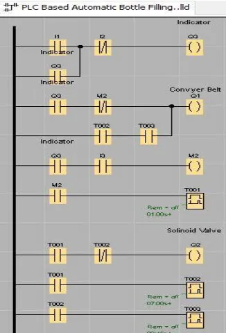
6. LADDER DIAGRAM
The ladder diagram for the system is shown in figure 5. To turn on the PLC, the switch at port I1 is used and to turn it
OFF the switch at port I2 is used. When system is started by I1 than the conveyor belt (Q1) and indicator (Q3) will be
datrats as well. When I3 sensed by photo sensor at that
time, the conveyor belt (Q1) will be stopped after one
second from timer T001, the solenoid valve leblllitopened.
When solenoid valve will be opened at that time, the bottle will be filled within 30 seconds.llAfter 30 seconds, from
timer T002, the solenoid valve will be closed. From timer T003, it takes 45ms to start the conveyor belt (Q1). enthl
htral itaaltl eblll ttftl bhl mrthal tml antl intatl dthdtrl ahis
process will continue.
Fig-5:Ladder Diagram
7. ALGORITHM
Algorithm is vital part for program. To write a logical step by step method to solve the problem is called algorithm. The algorithm for the system is in the following steps:
Step 1: I1 is sensed by push button.
Step 2: Conveyor system Q1 is activated by I1.
Step 3: I3 is sensed through photo sensor.
Step 4: If sensor I3 is detected any object or bottle, it
moves to the next step, if “NO” than returns to the step 3.
Step 5: If bottle is detected through photo sensor I3 than
conveyor system Q1 will stop and solenoid valve Q2 will
open.
Step 6: If the bottle is fulfilled, it moves to the next step, if “NO” than it will stay at step 5.
Step 7: If the bottle is fulfilled than conveyor system Q1
will start and solenoid valve Q2 will stop.
Step 8: If another bottle is detected through photo sensor I3, then it returns to step 5, if “NO” than it will stay at step
7 or manually it can be turned off.
8. FLOW-CHART
A flowchart is the graphical or pictorial representation of an algorithm with the help of different symbol, shapes and arrows in order to demonstrate a process or a program. Figure 6 shows the flowchart of our program. At first, the system will energize by power supply. If I1 is sensed by
push button than the conveyor system will start. If a bottle is detected through the sensor I3, the process will move to
step 5, but if a bottle is not detected, the process returns to step 3. In step 5 operation, the conveyer belt is stopped and the bottle is filled by activating the solenoid valve. After the bottle is filled up, the system goes to step 7.
If another bottle is detected through the sensor I3 then the
process retunes to step 5, but if a bottle is not detected, than the process stay at step 7 or manually it can be turned off.
8. PERFORMANCE OF MACHINE
[image:3.595.79.242.508.748.2]© 2018, IRJET | Impact Factor value: 6.171 | ISO 9001:2008 Certified Journal | Page 303 Fig-6:Flow-chart
9. SHORTCOMING
It can only fill one bottle at a time. This process can be efficiently used in water filling system. These types of fluids are operated mainly by using the solenoid valve and nozzle. So the range of fluid types is not so wide. Positioning the solenoid valve is a critical issue and proper care is needed. This system is constrained by height (max 6.6’’ inch) of the bottle of a specific volume.
10. CONCLUSIONS
PLC is immensely useful device in automation system to increase production of goods. The production of goods is being increased by automation system. Consequently, it can develop economic growth. The main goal of this paper is to implement “PLC based automatic bottle filling system”. The cost of machine installation is not cheap and it is a time consuming work. But it can run for a long period of time. The performance of this machine is depending on the cost of installation. This machine has been implemented successfully. In this machine, PLC has been used to control the overall system by using ladder logic. The overall process is more reliable. It also time saving and operating system of this machine is so easy.
REFERENCES
[1] T.Kalaiselvi and R.Praveen, “PLC Based Automatic Bottle filling and Capping System with User Defined Volume Section,” International Journal of Emerging Technology and Advance Engineering 2012, pp. 134-138.
[2] D.Baladhandabany and S.Gowtham, “PLC Based Automatic Liquid Filling System,” International Journal of Computer Science and Mobile Computing 2015, pp. 684-692.
[3] Blog. (2014, September 09). The basic of PLC operation [Online]. Available: https://goo.gl/duSiwm
[4] Peter. (2015, June 27). Ladder Logic Examples and PLC Programming Examples [Online]. Available: https://goo.gl/87UDVb
[5] Siemens. (2003, June). LOGO! [Online]. Available: https://goo.gl/3UWsqx
BIOGRAPHIES
Md. Abdulla Al Nakib received B.Sc. in Electrical & Electrical Engineering from Presidency University, Dhaka, Bangladesh in 2017. He wants to pursue his Masters Studies in Sweden. His research interests include Electronics, Automation and Embedded Electronics System Design.
© 2018, IRJET | Impact Factor value: 6.171 | ISO 9001:2008 Certified Journal | Page 304
Shahruk Osman received the B.Sc.