© 2017, IRJET | Impact Factor value: 6.171 | ISO 9001:2008 Certified Journal | Page 675
Humanoid Dual Arm Robot with Neural Learning of Skill Transferring
Control
Mrs. G.Sangeetha Lakshmi
1, Ms. K. Indumathi
2, Ms. K. Gowthami
31Assistant Professor, Dept of Computer Science and Applications, D.K.M College for Women (Autonomous),
Vellore, Tamilnadu, India.
2,3 Research Scholar, Dept of Computer Science and Applications, D.K.M College for Women (Autonomous),
Vellore, Tamilnadu, India.
---***---Abstract - This arrangement of visual serving (VS) control
and neural network (NN) learning on humanoid dual-arm robot. A VS control system is built by using stereo vision to obtain the 3D point cloud of a target object. A least square-based method is planned to reduce the stochastic error in workspace standardization. An NN controller is designed to pay for the erect of doubts in payload and other parameters during the tracking control. In contrast to the conventional NN controller, a deterministic learning technique is utilized in this work, to enable the learned neural knowledge to be reused before current dynamics changes. A skill transfer mechanism is also developed to apply the neural learned knowledge from one arm to the other, to increase the neural learning efficiency. Tracked path of object is used to provide target position to the coordinated dual arms of a Baxter robot. Robotic implementations have demonstrated the efficiency of the developed VS control system and have verified the effectiveness of the proposed NN controller with knowledge reuse and skill transfer features.
Keywords: Visual Serving, Humanoid Dual-arm, tracking control, Baxter Robot, Stochastic error
1. INTRODUCTION
The issues pertaining to robot control have gained increasing research attention, recently. Visual serving (VS) is a technique of control using computer vision information to control the motion of a robot. It mainly depends on techniques of computer vision, image processing and control theory. It is of great importance in improving the edibility of robot control systems and has been widely applied. There are two central setups of the camera and the robot end-ejector: eye-in-hand, or End-point open-loop control, in which the position of the object is watched by the camera appended to the robot hand; eye-to-hand, or end-point closed-loop control, in which the movement of the end-ejector and the object are both watched by a camera settled on the world frame. There were several approaches aiming to provide a better observation of target objects by increasing the number of cameras, e.g. a system using multiple cameras and a combination of eye-in-hand camera and eye-to-hand camera system. However, they have low adaptability to a changing environment. In this paper, the control of a Baxter robot arm end-ejector using a stereo visual camera ZED as the eye-to-hand camera is addressed.
Due to a narrower held of view that eye-in-hand VS provides, as the sensors are attached in the hand. A least squares-based method is proposed to reduce stochastic errors during camera calibration process.
To improve robot arms control performance, an adaptive controller was developed for robot manipulators. It employed a barrier Lyapunov function-based synthesis to design controller for the manipulator to operate in an ellipsoidal con-strained region. An adaptive neural network (ANN) control for the robot system in the presence of full-state constraints is designed. The NN enables the System to deal with uncertainties and disturbances effectively. Among these work, we see that NN technique has been extensively used for robot control system due to its universal approximation ability and its capability to cope with unmodeled dynamics of the robot systems. The highly nonlinear nature of the robot dynamics makes it challenging to obtain an accurate model under practical operational conditions. However, conventional NN control was focused on internal uncertainties. To overcome the uncertainties that arise from unknown payload, a novel NN-based intelligent controller is designed in this paper and obtains an enhanced performance of VS control.
© 2017, IRJET | Impact Factor value: 6.171 | ISO 9001:2008 Certified Journal | Page 676 With the aim of improving the intelligence of robot, a
robot-to-robot skill transfer mechanism is proposed. By using surface electromyography signal, human arm stiffness was extracted to transfer human writing skills to robot. A communication language was developed of transferring grasping skills from human user to a robot. Unlike these conventional approaches of transferring human skills to robot, the learned knowledge from NN controller is transferred from arm-to-arm with dual-arm robot. With guaranteed performance, NN controller only needs to learn once about the system uncertainties on one side of dual-arm. The other arm can perform the same task without readapting the same uncertainties. It can help to increase the neural learning efficiency and also to further reduce the computational load.
In this context, this paper presents a neural learning enhanced VS control system with knowledge reuse and skill transfer features. The system was successfully implemented on a Baxter humanoid robot and test results are demonstrated, which show the potential of the novel learning controller.
Preliminaries Consider a parameterized linear time-varying (LTV) multivariable system in the following form:
Where
2. KINEMATICS MODELING OF HUMANOID BAXTER ROBOT ARMS
2.1. Dual-arms workspace identification for humanoid Baxter robot
Baxter robot is a humanoid robot with an identical pair of seven degree of freedom (DOF) manipulators installed. Each manipulator has seven rotational joints and eight links as shown in Fig. 1(a). The names of the arm joints are labeled in Fig. 1(b).
[image:2.595.325.540.127.301.2]Baxter robot's kinematic model together with Denavit– Hartenberg (DH) Para-meters and joint rotation limits were discussed from our previous work.
Fig. 1.Baxter humanoid robot and its joint labels. S0 shoulder roll, S1 shoulder pitch, E0 elbow roll, E1 elbow
pitch, W0 wrist roll, W1 wrist pitch, W2 wrist roll.
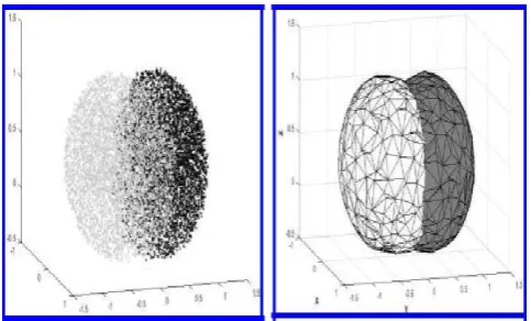
It is essential to estimate the robot manipulator workspace for optimized robotic design and algorithm. The previous method used on single armies extended to both arms to calculate the reachable workspace. Randomly chosen 6000 points in the joint space for each arm were generated by using homogeneous radial distribution. Then, point clouds of the reachable workspace for both manipulators were generated based on the end-ejector positions calculated with forward kinematics, as illustrated in Fig. 2(a). Furthermore, Delaunay triangulation is applied to the point cloud to generate a convex hull of the joint space, as illustrated in Fig. 2(b). These are used to constrain the individual workspace for left and right arms independently in order to let them co-operate more efficiently.
The point cloud of reachable workspace of Baxter robot arms
The convex hull of reachable workspace of Baxter robot arms
[image:2.595.313.555.532.678.2]© 2017, IRJET | Impact Factor value: 6.171 | ISO 9001:2008 Certified Journal | Page 677
3. SETUP OF STEREO VISION SENSOR
3.1
System structure overviewThe robot control system is shown in Fig. 3. The ZED stereo camera is a passive depth camera consists of two RGB-cameras with fixed alignment. It is used as the visual sensor by the robotic control system. It captures videos in 30 frames per second (fps) under 1280 720 resolutions to produce dense colored depth maps for estimating the positions of objects. In experiments, ZED keeps capturing videos of objects by its two sensors and sends them to a client computer via a Universal Serial Bus (USB) 3.0 cable. Based on the difference between two videos, client computer constructs disparity maps where the 3D position information of objects can be read. Then, the target object's position information will be sent to the Sever Computer via User Datagram Protocol (UDP) packets. Sever Computer will receive, decode them and then command Baxter to follow the target object along a reference trajectory.
3.2. Stereo camera calibration
Raw pictures captured by ZED are distorted because lenses in ZED introduce non-linear lens distortion deviating from the simple pin-hole model. To solve this problem, camera parameters calibration is necessary. The aim is to ¯nod out the camera parameters such as the intrinsic, extrinsic and distortion. Usually researchers used a 2D checker-board pattern to evaluate them; avoiding complexity of 3D reference models and high cost of precise calibration objects. In our work, these parameters are provided by the manufacturer, we can employ them directly.
After we completed the camera parameters calibration, undistorted pictures can be captured from ZED. Then, we can get object's coordinates in ZED coordinate system. However, in practice, the position of objects is presented in Baxter coordinate system rather than ZED. Therefore, we need to transform the ZED coordinates into the Baxter coordinates, i.e. the position calibration is necessary.
The transform equation:
Where T is the transformation matrix. (Xi; Yi;Zi) represents
the ZED coordinates and (xi;yi;zi) represents the Baxter
coordinates. The aim of position calibration is to form the coordinate transform matrix T. T can be achieved by
where (xi;yi;zi) and (Xi; Yi;Zi), i = 1, 2, 3, 4, are four
non-coplanar point coordinates in the robot coordinate system and the ZED coordinate system, respectively.
To measure coordinates in Baxter coordinate system, the simplest way is to use rulers. However, it is very coarse because the origin of the Baxter coordinate system is inside Baxter's body which is unavailable. Furthermore, it is also hard to ensure the horizontality and verticality of the ruler. Another way to measure coordinates is to use the kinematics of Baxter. At first some established reference coordinates are given and then we command Baxter's end-ejector to move to these positions by using kinematics. In this way, we can get the end-ejector's coordinates without direct measurement. Then, we use ZED to measure the end-ejector's coordinates in ZED's coordinate system, which will be introduced in the next section. In this way, the point’s coordinates in both Baxter coordinate system and ZED in Eq. (4) are easily achieved.
© 2017, IRJET | Impact Factor value: 6.171 | ISO 9001:2008 Certified Journal | Page 678 While A is a known matrix with dimension of 4n x 16. X
represents the transformation matrix T with dimension of 16 1. B is a column vector with dimension of 4n x 1. In most cases, this equation has no solution. However, we can compute the least square solution of it by the following approach. Initially, Eq. (6) is transformed as below:
If ATA is nonsingular, the transformation matrix can be
calculated as below:
According to Eq. (8), the solution of Eq. (5) can be achieved, i.e. the transform matrix T can be solved by the method of least squares. We can get a more precise solution by completing more coordinates measurement in ZED and Baxter.
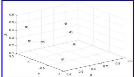
Since the robot arms contain red color, and green color itself is easily impacted by illumination, a blue object was used for detection. Initially, the (Xi; Yi;Zi), i = 1, 2, 3, 4 of the object's
centroid from four different positions were obtained, out of ZED camera, as the black XYZ shown in Fig. 4(a). The end-ejector's position (xi ;yi ; zi),i =1,2,3,4 were recorded
simultaneously. The end-ejector was posed10 cm behind the object's centroid, in order to follow the object without blocking the object from camera view, as the white xyz shown in Fig. 4(a).
Then we substituted (xi;yi;zi) and (Xi; Yi;Zi), i = 1, 2, 3, 4 were
substituted into Eq. (5) to get the transformation matrix T. T will be applied to the object's centroid position, and the data will be sent to the robot as reference coordinates for following the object. The results are shown in Figs. 4(b) and 5, black XYZ stands for object's reference coordinates and white xyz stands for the coordinates that robot end-ejector actually followed.
3.3. Theory of depth measurement in ZED
Both pictures captured under active ambient lighting by the ZED stereo camera are aligned utilizing the camera intrinsic and are amended for distortion. In this way, the undistorted images will be stereo rectified to adjust both the projection plane’sepipolar lines and guarantee comparable pixel’s present in a predetermined row of the image. The pictures acquired are then frontal paralleled and are estimated correspondingly. The fundamental and the essential frameworks are figured by utilizingepipolar geometry. There are seven parameters in the fundamental matrix representing two image’s pixel relations, three for two image planeshomographic and two for each epipole. The essential matrix has five parameters in a 3 x 3 matrix; three of them are the rotation values between the camera projection planes and two for translation. Then, the epipolar lines were
adjusted and the epipoles was moved to infinity. Figure 6(a) delineates the results of stereo correction with row adjusted pixels.
The definition of variables utilized underneath is given in Table 1. Stereo correspondence is a technique for coordinating pixels with comparative surface texture over two co-planar picture planes. The separation between the columns of these splendidly coordinated pixels is characterized as d =xt- xr
Fig. 5. Precision of calibration. Cross mark: object's position. Circle mark: end-ejector's position.
(a) Rectified stereo images (b) Disparity map.
Fig. 6. Stereo images and 3D reconstruction.
Block matching is actualized for assessing the image correspondence. With the use of sum of absolute differences (SAD), a 15-pixel window block is used to discover the matching results. Considering computational load, the disparity range is selected as low as [0 40] to match the low texture difference of the experiment environment.
Table 1. Definition of variables.
1 xl
Column value of left image pixel
2 xr
Column value of right image pixel
3 D Depth (mm)
[image:4.595.318.549.210.342.2] [image:4.595.318.550.387.534.2]© 2017, IRJET | Impact Factor value: 6.171 | ISO 9001:2008 Certified Journal | Page 679 5 F Focal length (mm)
6 D Disparity
7 P Projection matrix
8
X/, Y/,
Z/ 3D world coordinates
In order to get a more complete outcome, Semi-Global method is used to drive the disparity values to the neighboring pixels. The output of disparity map is illustrated in Fig. 6(b). Disparity can be calculated by the triangulation equation D = B (f/d). It isinverselyproportional to the depth of the pixel. Bouguets algorithm is used to obtain the Cartesian coordinates from the reconstruction of the image, and the equation is
P[x; y; d; 1]T= [X, Y , Z,]T; (9)
where1 is the homogeneous component.
4. DETECTION AND LOCALIZATION OF TARGET OBJECT
4.1 Color object detection
Color-based segmentation is utilized in order to isolate a single color object from the captured image. One approach is to convert the entire RGB frame into corresponding hue-saturation-value (HSV)-plane and concentrate the pixel values of the color you want to detect. By using this method, you may be able to detect almost every single distinguishable color in a frame. However, implementing this approach in live video is challenging because of ambient light. An alternative approach has been used in this paper in view of our previous work, to convert the captured image into L*a*b* color space where the value of “a" and “b" is related to the color information of a point.
During the experiments, all images are converted into L*a*b* color space and the variance between every point's color and the standard color marks will be calculated. The estimations are selected based on the minimum variance value of each images. Furthermore, intersection of the diagonals was used to calculate the centroid and Harris corner detector was used to calculate the corners of the object. According to the centroid point in the image, the object's coordinates in ZED is then extracted from the images. By applying the transformation matrix in Sec. 4.2, the object's coordinates in Baxter's coordinate system can be calculated. Figure 4(b) demonstrates the calculated centroid of the object in robot coordinates after the coordinate transformation.
4.2. Object detection regulation
In experiments, we find that because of the nonuniform distribution of light in space, object's color in images keeps changing as the object moves. Sometimes the value of “a" and “b" changes considerably and it affects the stability of object
detection. To solve this problem, a regulation algorithm in object detection was employed. The algorithm is described below. (i) Calculate the variance between the image points' color and the color marks. (ii) If the value of the variance of the object is not so large, go back to (i) and continue next detection. Conversely, go to (iii). (iii) Calculate theaverage value of “a" and “b" around the centroid points, and update the older color marks with the new value. Then, start next detection based on these new color marks.By employing the algorithm above, object detection becomes more stable and more adapted to the environment.
5. CONTROL AFTER NN LEARNING
During the last set of experiments, the NN will ¯rst learn the dynamics while both manipulators tracking the object along a repeated trajectory, same as previous two. After four cycles, the NN was adapted with the external dynamics (attached pay-load). So that the trained NN will be reused for the further teleoperation. The control torque inputs of right and left arms are shown in Figs. 10(c) and 10(d). The per-formance of tracking is illustrated in Fig. 8(c).From Fig.8(d), it can be seen that the designed adaptive controller can help system to compensate tracking error from both internal and external dynamics. The trained NN has a steady performance with reusing the trained knowledge to increase tracking performance.
6. CONCLUSION
An NN learning enhanced VS control method was developed in this paper and implemented on a humanoid dual-arm Baxter robot. The object and its color was detected by a stereo camera and an regulation algorithm was applied to ensure the e®ectiveness of detection. The calibration between camera and robot's coordinates was done with the proposed least square-based method to reduce stochastic errors.The dynamic parameters of the manipulator are estimated by the radial basis function NN and an improved adaptive control method is designed for compensating the e®ect of uncertain payload and other uncertainties during the dynamic control of the robot. Speci¯cally, a knowledge reuse method with skill transfer feature has been created to increase the neural learning decency. This ensures that the learned NN knowledge can be easily reused furnishing repetitive tasks and also can be transferred to another arm for performing the same task. The proposed NN controller was validated with tests on a Baxter humanoid robot, and can realize optimal perfor-mance of the designed VS control.
REFERENCES
[1] B. Siciliano, L. Sciavicco, L. Villani and G. Oriolo, Robotics: Modelling, Planning and Control, Springer Science Business Media (Springer, 2010).
© 2017, IRJET | Impact Factor value: 6.171 | ISO 9001:2008 Certified Journal | Page 680 [3] S. Hutchinson and F. Chaumette, Visual servocontrol,
Part II: Advanced approaches, IEEE Robot. Automat. Magn. 14(1) (2007) 109–118.
[4] S. L. Dai, M. Wang and C. Wang, Neural learning control of marine surface vessels with guaranteed transient tracking performance, IEEE Trans. Indust. Electron. 63(3) (2016) 1717–1727.
[5] A. Loria and E. Panteley, Uniform exponential stability of linear time-varying systems: Revisited, Syst. Control Lett. 47(1) (2002) 13–24.
[6] C. Yang, S. Amarjyoti, X. Wang, Z. Li, H. Ma and C. Y. Su, Visual servoing control of Baxter robot arms with obstacle avoidance using kinematic redundancy, in Int. Conf. Intelligent Robotics and Applications (Springer International Publishing, 2015), pp. 568– 580.
[7] C. Wang and D. J. Hill, Deterministic Learning Theory for Identification, Recognition, and Control, Vol. 32 (CRC Press, 2009).
[8] C. Wang and D. J. Hill, Deterministic learning and rapid dynamical pattern recognition, IEEE Trans. Neural Networks 18(3) (2007) 617–630.
[9] Z. Xue, C. Wang and T. Liu, December. Deterministic learning and robot manipulator control, in IEEE Int. Conf. Robotics and Biomimetics (ROBIO) (2007), pp. 1989–1994.
[10] C. Wang and T. Chen, Rapid detection of small oscillation faults via deterministic learning, IEEE Trans. Neural Netw. 22(8) (2011) 1284–1296.
[11] P. Liang, C. Yang, Z. Li and R. Li, Writing skills transfer from human to robot using sti®ness extracted from SEMG, in IEEE Int. Conf. Cyber Technology in Automation, Control, and Intelligent Systems (CYBER) (2015), pp. 19–24.
[12] M. Ralph and M. A. Moussa, Toward a natural language interface for transferring grasping skills to robots, IEEE Trans. Robot. 24(2) (2008) 468–475.
[13] F. Chaumette and S. Hutchinson, Visual Servoing and Visual Tracking (Springer, Berlin, 2008).
[14] C. Dune, E. Marchand and C. Leroux, One click focus with eye-in-hand/eye-to-hand cooperation, in IEEE Int. Conf. Robotics and Automation (2007), pp. 2471–2476.
[15] E. Guizzo and E. Ackerman, How Rethink Robotics Built Its New Baxter Robot Worker (2017). Available at http://sdk.rethinkrobotics.com/wiki/Hardware Speci¯cations [acces-sed on 1 March 2017].
[16] W. He, Y. Chen and Z. Yin, Adaptive neural network control of an uncertain robot with full-state constraints, IEEE Trans. Cybern. 46(3) (2015) 1.
[17] H. Hirschmuller, Accurate and e±cient stereo processing by semi-global matching and mutual information, in IEEE Computer Society Conf. Computer Vision and Pattern Recognition (CVPR), Vol. 2 (2005), pp. 807–814.
[18] S. Hutchinson, G. D. Hager and P. I. Corke, A tutorial on visual servocontrol, IEEE Trans. Robot. Automat. 12(5) (1996) 651–670.
[19] Z. Ju, C. Yang and H. Ma, Kinematics modeling and experimental veri¯cation of Baxter robot, in 33rd Chinese Control Conf. (CCC ) (2014), pp. 8518–8523.
[20] J. Stavnitzky and D. Capson, Multiple camera model-based 3D visual servo, IEEE Trans. Robot. Automat. 16(6) (2001) 732–739.
[21] K. P. Tee, S. S. Ge, R. Yan and H. Li, Adaptive control for robot manipulators under ellipsoidal task space constraints, in IEEE/RSJ Int. Conf. Intelligent Robots Systems (2012), pp. 1167–1172.