© 2017, IRJET | Impact Factor value: 5.181 | ISO 9001:2008 Certified Journal | Page 157
Speed Controller Design of PMSM using Balanced Model Reduction
Technique and CRA Method
K.Navya
1, Dr. N.Prema kumar
21
PG student, Dept of EEE, Andhra University (A), Vishakhapatnam, India
2Professor, Dept of EEE, Andhra University (A), Vishakhapatnam, India
---***---Abstract
Model order reduction gives systematicapproximation of complex models. This paper deals with speed control of permanent magnet synchronous motor (PMSM) using (CRA) characteristic ratio assignment method and the balanced reduction (BR) theory to obtain reduced-order models from dynamic system equivalents of electric system. BR allows obtaining reduced-order models via a process in which the original asymptotic stable system is internally balanced. The balanced system is truncated according to its dominant dynamics. The simulation and response[11] are obtained by using MATLAB software.
Key Words: Balanced reduction (BR), Permanent Magnet Synchronous Motor (PMSM), Characteristic ratio assignment method (CRA)
1. INTRODUCTION
Permanent magnet synchronous motors (PMSM) are typically used for high-performance and high-efficiency motor drives High-performance motor control is characterized by smooth rotation over the entire speed range of the motor, full torque control at zero speed, and fast acceleration and deceleration. To achieve such control, vector control techniques are used for PM synchronous motors Compared to a DC motor, the PMSM misses a commutator therefore it is more reliable than a DC motor. The PMSM also has advantages when compared to an AC induction motor. PMSM machines have the unique advantages of unsurpassed efficiency and power density characteristics, which are primarily responsible for their wide appeal [1] [2].
On the other hand, PMSM machines are synchronous, which certainly requires accompanying power electronics, but they also provide the basis for achieving high-quality actuator control. The speed control of PMSM motor is done by design of controller by CRA method, adjustment of speed of the motor and the damping ratio can be determined by only one parameter [6]. Therefore, this technique is user friendly for tuning controller under the requirement of the system where coming to Model order reduction concerns systematic approximation of complex models. The topic has received a great deal of attention in the control community at least since the early 1980’s
The High-order systems (HOS) are always costly and tedious. Model order reduction (MOR) [7] is used for Simplifying complicated problems in HOS.
In this paper the selection of order reduction technique is based on balanced truncation method. The procedure of implication is based on using mathematical approaches of balanced truncation[3]. It is based on introducing a special joint measure of controllability and observability for every vector in the state space of an LTI system [5]. Then, the reduced model is obtained by removing those components of the state vector which have the lowest importance factor in terms of this measure
2. MATHEMATICAL MODEL OF A PMSM DRIVE
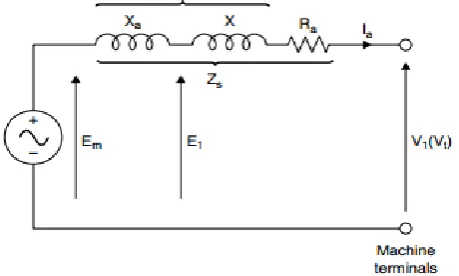
The most convenient way to determine the performance characteristics of machines is by means of their electrical equivalent circuits. The steady state model of the PMSM is used for studying steady state performance of the system only [1] this implies that all the electrical transients are neglected during load changes and frequency variations. Fig1 gives the steady state equivalent circuit of a synchronous machine. These equivalent circuits can become very elaborate when saturation, armature reaction, harmonic reactance, and other nonlinear effects are introduced
[image:1.595.320.550.556.694.2]© 2017, IRJET | Impact Factor value: 5.181 | ISO 9001:2008 Certified Journal | Page 158
(Here X = leakage reactance, = armature reaction
reactance, = + X = synchronous reactance, =
armature resistance, = synchronous impedance, =
terminal voltages, = magnetizing voltage)
The modeling of PMSM is done through transfer function approach which is given below
(1)
(2)
(3)
(4)
Where (5)
(6)
(7)
Assuming all the equations from (1) to (3) are non-linear and forced to zero according to vector control of PMSM. Then equations (1) to (3) can be solved as given below (8)
(9)
(10)
The transfer function of PMSM is given below Where the overall transfer function of the practical PMSM motor is given as 3. Balanced Truncation Method As we know that the higher the order of the model, will be more complex [8-9]. Therefore, there is need to reduce higher order model to lower order model. This method was first proposed by Gustafson where reduced order models are obtained by neglecting higher order terms from numerator polynomials and denominator polynomials As we know that the higher the order of the model, will be more complex. Therefore, there is need to reduce higher order model to lower order model. The proposed method of model reduction is balanced reduction method Consider the stable liner time invariant LTI high-dimensional System Let The original order linear time invariant system is (11a) (11b) Where from equation (11) it is assumed to be asymptotically stable and characterized by the system matrices A, B, C and D where in general D is assumed to be zero (12a) (12b) Two major characteristic of dynamic system are its controllability ( i.e., it represents a quantitative measure of the coupling of inputs to the state behavior, and its observability ( represents strength of the coupling between outputs and the state behavior[10] (13a) (13b) Equation (13) satisfies the Lyapunov equation (14a) (14b) Using a new co-ordinates system via transformation matrix to make the internal responses by and equal in magnitude; (15)
Where and corresponds to controllability balanced
co-ordinates and observability co-ordinates systems respectively where is a diagonal matrix consists of Hankel singular value , i=1,…n, also known as second order modes. Where the Hankel singular value are given by the square roots of the eigenvalues of the product of the two gramians
and i.e,
© 2017, IRJET | Impact Factor value: 5.181 | ISO 9001:2008 Certified Journal | Page 159
Similarly Transformation can be found from the
eigenvalue problem
(17)
Such that the balanced domine, i.e., become
equal and diagonal as in eq (15) the new co-ordinate system given by eq (17) allows obtaining the internally balanced
system ( as
=
(18a)
(18b) Balanced system in eq (18) gives the reordering and truncation modes (deleting states associated with the smallest singular values) can be applied to obtain the
reduced order model ( and with r < n and it is
shown that eq (18) results in to two asymptotically stable and internally balanced subsystem and that system is chosen as the reduced order system
And the reduced order of the system is given as
4. CHARACTERISTIC RATIO ASSIGNMENT METHOD:
The desired control response would be attainable by an all-pole commensurate fractional order transfer function. This closed loop transfer function is considered as follows [6]
(19)
The characteristic ratio for the system has the following relation
(20)
Parameters of the system (19) are expressed in function of the characteristic ratio and the generalized time constant,
For i = 2…n (21)
It is also possible to make the previous relation into a recursive form
In this section, the design of a fractional PI controller with time specification is developed. The structure of the PI can be written as
(22)
Let consider the following open loop transfer function
(23)
The obtained closed loop transfer function by applying the fractional PI controller is given by
(24)
The characteristic equation is expressed by
(25)
This equation is identified to the characteristic polynomial
(26)
Hence, the controller parameters can be determined using relations (25) and (26):
(27)
(28) Controller design is given as
(29)
(30)
© 2017, IRJET | Impact Factor value: 5.181 | ISO 9001:2008 Certified Journal | Page 160
5. SIMULATION RESULTS
0 5 10 15 20 25 30
0 0.2 0.4 0.6 0.8 Time(sec) A m pl it ud e
PMSM With Higher Order
PMSM WIth higher Order
Fig: 2 Step response of PMSM with Higher Order TF
0 5 10 15 20 25
0 0.2 0.4 0.6 0.8 Time(sec) A m pl it ud e
PMSM With Balanced Reduction
PMSM with Balanced Reduction Method
Fig: 3 Step response of PMSM with Balanced Reduction Method
0 5 10 15 20 25 30
0 0.5 1 Time (sec) A m pl it ud e
characteristic ratio assignment method
PMSM With Controller
Fig: 4 Response of PMSM with Controller Using CRA tuning Method
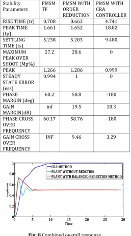
From the above responses of PMSM fed with inverter in Fig.2, and reduced order system using Balanced reduction method in Fig.3 and PMSM with controller using CRA method is in Fig.4 give the time response where all the stability parameters can be easily found and the peak time and rise time of the PMSM with inverter and reduced order response are calculated and they are given with 0.708, 0.663 and 1.661, 1.652 respectively, PMSM with controller is having zero maximum peak over shoot where the stability parameters and comparison is given in the Table.1 specified and the combined response of the system is given in Fig.8 to ensure the optimum result by comparison
10-4 10-2 100 102
-180 -135 -90 -45 0
P.M.: 60.2 deg Freq: 2.47 rad/s
Frequency (rad/s) -60 -40 -20 0 G.M.: inf Freq: Inf Stable loop
Open-Loop Bode Editor for Open Loop 1(OL1)
-1 -0.8 -0.6 -0.4 -0.2 0 -4 -3 -2 -1 0 1 2 3
4 0.21 0.15 0.105 0.07 0.044 0.02
0.32 0.55 0.02 0.044 0.07 0.105 0.15 0.21 0.32 0.55 0.5 1 1.5 2 2.5 3 3.5 4 0.5 1 1.5 2 2.5 3 3.5 4
Root Locus Editor for Open Loop 1(OL1)
Real Axis
Fig: 5 Root Locus and frequency response of Higher Order system
10-1 100 101 102 103 0
90 180 270 360
P.M.: 59 deg Freq: 2.5 rad/s
Frequency (rad/s) -40 -30 -20 -10 0 10
G.M.: 19.5 dB Freq: 5.92 rad/s Stable loop
Open-Loop Bode Editor for Open Loop 1(OL1)
-1 -0.5 0 0.5 1 1.5 2 2.5
-15 -10 -5 0 5 10 150.065 0.042 0.02
0.095 0.135 0.2 0.3 0.55 0.02 0.042 0.065 0.095 0.135 0.2 0.3 0.55 2 4 6 8 10 12 14 2 4 6 8 10 12 14
Root Locus Editor for Open Loop 1(OL1)
Real Axis
Fig: 6 Root Locus and Frequency Response of the plant with balanced reduction Method
10-2 100 102 104
-90 0 90 180 270 360
P.M.: -180 deg Freq: 0 rad/s
Frequency (rad/s) -60
-40 -20 0
G.M.: 10.4 dB Freq: 2.14 rad/s Stable loop
Open-Loop Bode Editor for Open Loop 1(OL1)
-20 -15 -10 -5 0 5
-15 -10 -5 0 5 10
150.82 0.7 0.56 0.42 0.28 0.14
0.91 0.975 0.14 0.28 0.42 0.56 0.7 0.82 0.91 0.975 2.5 5 7.5 10 12.5 15 17.5 20
Root Locus Editor for Open Loop 1(OL1)
Real Axis
Fig: 7 Root Locus and Frequency Response of the plant with controller using CRA method
© 2017, IRJET | Impact Factor value: 5.181 | ISO 9001:2008 Certified Journal | Page 161 comparisons are done in the same plot is shown in Fig.8 and
[image:5.595.34.292.170.634.2]the results are obtained through the MATLAB software [11]
Table -1: Response specifications (time and frequency domains) of PMSM with different configurations
Stability
Parameters PMSM TF PMSM WITH ORDER
REDUCTION
PMSM WITH CRA
CONTROLLER
RISE TIME (tr) 0.708 0.663 4.741
PEAK TIME
(tp) 1.661 1.652 18.82
SETTLING
TIME (ts) 5.238 5.203 9.480
MAXIMUM PEAK OVER SHOOT (Mp%)
27.2 28.6 0
PEAK 1.266 1.286 0.999
STEADY STATE ERROR (ess)
0.994 1 0
PHASE
MARGIN (deg) 60.2 58.8 -180
GAIN
MARGIN(dB) inf 19.5 10.3
PHASE CROSS OVER
FREQUENCY
60.17 58.76 -180
GAIN CROSS OVER FREQUENCY
INF 9.46 3.29
0 5 10 15 20 25 30
0 0.2 0.4 0.6 0.8 1
Time
A
m
p
li
tu
d
e
CRA METHOD
PLANT WITHOUT REDCTION
PLANT WITH BALANCED REDUCTION METHOD
Fig: 8 Combined overall response
6. CONCLUSIONS
This paper deals with speed control of PMSM where because of its wide range of applications. As it is of higher order the order reduction techniques are used we use balanced truncation (BR) method to achieve optimum order reduction of the plant where it is convenient to design a controller, the desired controller we use is CRA to get better performance of speed control of PMSM
REFERENCES
[1] Grzegorz SIEKLUCKI, Akademia Górniczo-Hutniczaw Krakowie “Analysis of the Transfer-Function Models of Electric Drives with Controlled Voltage Source”
[2] Transfer function determination for a PM synchronous AC motor
[3] M. Dalir and M. Bashour "Applications of Fractional Calculus". Applied Mathematical Sciences, Vol. 4, pp. 1021 - 1032.2010
[4 ] Emna Ouhibi, Maher Ben Hariz, and Faouzi Bouani “Design of fractional order PI controller using the CRA method
[5] Henrik Sandber” Parameterized Model Order Reduction Using Extended Balanced Truncation”
[6] Jutarut Chaorai-ngern, Arjin Numsomran, Taweepol Suesut, Thanit Trisuwannawat and Vittaya Tipsuwanporn. ” PID Controller Design using Characteristic Ratio Assignment Method for Coupled-Tank Process”
[7] Zur Erlangung des Grades eines Doktors der Naturwissenschaften (Dr. rer. nat.) am Fachbereich Mathematik & Informatik der Freien Universita¨t Berlin “Comparison of Balance Truncation and Singular Perturbation Approximation with Application to Optimal Control”
[8] Dr.S.Janardhanan “Model Order Reduction and Controller Design Techniques”
[9] Abner Ramirez, Senior Member, IEEE, Ali Mehrizi-Sani, Senior Member, IEEE “Application of Balanced Realizations for Model-Order Reduction of Dynamic Power System Equivalents”
[10] Sudipta Ghosh, and Nilanjan Senroy, Member, IEEE “A Comparative Study of Two Model Order Reduction Approaches for Application in Power Systems”
[11] David Houcque Northwestern university “Introduction to MATLAB for engineering students”
Biographies
K. Navya, M. Tech. (Control Systems Engineering), Dept of Electrical Engineeirn, Andhra University (A), Vishakhapatnam-530003. India
[image:5.595.37.292.177.618.2]