N A N O E X P R E S S
Open Access
Generating and measuring the anisotropic elastic
behaviour of Co thin films with oriented surface
nano-strings on micro-cantilevers
Vicente Madurga
*, José Vergara and Cristina Favieres
Abstract
In this research, the elastic behaviour of two Co thin films simultaneously deposited in an off-normal angle method was studied. Towards this end, two Si micro-cantilevers were simultaneously coated using pulsed laser deposition at an oblique angle, creating a Co nano-string surface morphology with a predetermined orientation. The selected position of each micro-cantilever during the coating process created longitudinal or transverse nano-strings. The anisotropic elastic behaviour of these Co films was determined by measuring the changes that took place in the resonant frequency of each micro-cantilever after this process of creating differently oriented plasma coatings had been completed. This differential procedure allowed us to determine the difference between the Young’s modulus of the different films based on the different direction of the nano-strings. This difference was determined to be, at least, the 20% of the Young’s modulus of the bulk Co.
PACS: 62.25.-g; 81.16.Rf; 68.60.Bs; 81.15.Fg; 68.37.Ef; 85.85.+j
Introduction
The study of the elastic and mechanical properties of thin films is of interest in basic and applied research because thin films are used extensively in micro-electronic and micro-electromechanical systems. Because the elastic con-stants of thin films are different from those of bulk mate-rial of the same composition, the elastic constants of the bulk material cannot be used to design thin film devices. Consequently, it is very important to accurately determine the elastic constants of thin films. These properties can be studied using a wide variety of techniques, including the analysis of the substrate curvature [1], micro-beam testing [2], micro-tensile testing [3], cantilever-bending resonance [4], nano-indentation [5], Rayleigh-wave velocity measure-ments [6] and Brillouin scattering [7]. Among others, Young’s modulus is an important parameter for thin-film technological applications.
Micro-cantilevers (MCLs) are mechanical devices with attractive applications; for instance, they are widely used as high-sensitivity sensors in different physical, chemical and biological technologies [8,9]. Another use of MCLs
is in the study of the mechanical properties of thin films [10]. This type of analysis is possible because of the rela-tion between the resonant frequency of MCLs and Young’s modulus. If a MCL is coated with a thin film, a change results in the resonant frequency. By measuring this change, one can compute the Young’s modulus of the thin film deposited on the MCL.
We conducted a study that demonstrated that the off-normal pulsed laser deposition (PLD) technique allows the simultaneous growth and sculpting of soft magnetic nano-strings with an orientation that is perpendicular to the incidence plane of the plasma and a medium width that can be selected between 8 and 30 nm by selecting an off-normal angle and the appropriate deposition time [11]. Uniaxial in-plane magnetic anisotropy was then generated in the films that would have a value between 103 and 104 J/m3, depending on the deposition para-meters [11]. In addition to magnetic anisotropy, these nano-scale patterned Co films also presented controlled electrical, optical [12] and mechanical anisotropies [13]. In an extension of the study, MCLs were coated with these magnetic nano-strings so that their magneto-mechanical properties were analysed [14].
In this study, we produced Co nano-strings over Si MCLs, validating a differential method of studying the * Correspondence: [email protected]
Laboratory of Magnetism, Department of Physics, Public University of Navarre, Campus Arrosadía s/n, Pamplona 31006, Spain
elastic anisotropy of these Co thin films in connection with their nano-string morphology. This technique allowed us to determine the difference between the Young’s modulus of the films depending on their nano-string direction.
Experimental procedures
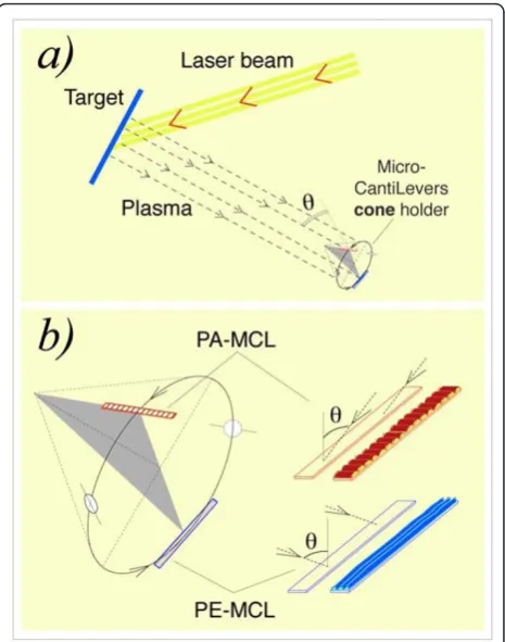
Si MCLs, 450 × 50 × ≈ 2 μm3 were coated with Co using PLD via an off-normal-incidence plasma proce-dure. A Nd:YAG laser beam (l= 1054 nm, 20-Hz repe-tition rate, 240 mJ per 4.5-ns pulse, ≈12 GW, target spot area ≈12 mm2) was driven onto a pure, polished Co target located inside a chamber with a base pressure of 10-6mbar. The target rotated at 32 rpm and angle of the laser beam from normal to the target was 45°. The MCLs were positioned at a distance of 73 mm from the target and were placed on the lateral surface of a cone with an angle ofπ-2θ; the axis of the cone was parallel to the direction of the plasma to allow deposition at an off-normal angle, θ, as shown in Figure 1. In this study, the plasma generated reached two MCLs at an off-nor-mal angle ofθ= 55°. The cone rotated around its axis at 73 rpm. MCL holders were designed to allow the simultaneous off-normal coating of two MCLs, one par-allel (PA-MCL) and one perpendicular (PE-MCL) to the generatrix of the cone, as shown in Figure 1b. Each MCL was located at each end of the diameter of a circle, a circular section perpendicular to the cone axis. Due to the cone rotation and the position of the two MCLs, the MCLs travelled through the plasma in exactly the same circumference, which ensured that each was coated with the same amount of material.
This designed, homemade device allowed the inci-dence plane of the plasma to be parallel or perpendicu-lar to the longitudinal direction of each MCL. Therefore, the nano-strings generated in the off-normal deposited film were perpendicular (transverse) or paral-lel (longitudinal) to the longitudinal direction of each MCL, as shown in the right part of Figure 1b. In addi-tion, two glass circles that were 7 mm in diameter were situated on the cone’s lateral surface in the same cir-cumference of the two MCLs. This made it possible to perform magnetic measurements.
The two MCLs were selected after the resonant fre-quency of each,νo, had been determined. The two MCLs were similar because of their equal dimensions and because we did not allow differences between the fre-quencies of the two selected MCLs higher than 20 Hz in ≈10000 Hz. The two MCLs were simultaneously coated with Co in consecutive processes, either with the same coating time or with different coating times, whereas the rest of the parameters remained unchanged.
The same device was used to coat two MCLs with Au under the same conditions, which ensured that our
device coated the two MCLs with the same amount of material.
The mechanical resonant frequency of the MCLs,νo prior to coating andν(C-MCL) after coating, was deter-mined through location as the working MCL in the head of an atomic force microscope (AFM) [15]. The system performed a driving frequency scan for mechani-cal oscillation of the MCL, measuring the amplitude and the phase of the MCL’s deflection. In this way, the MCL’s resonant frequency, ν, was determined. The accuracy of theνmeasurements was ± 1/10000.
Scanning tunnelling microscopy (STM) was performed to image the surface morphology of the coated glass cir-cles and also the coated MCLs.
[image:2.595.306.539.88.384.2]The magnetic hysteresis loops of the coated glass cir-cles were determined using a vibrating sample magnet-ometer [14]. The value of the measured magnetic
moment of each film was used to deduce its thickness. A deposition rate of ≈1.02 nm/min was used in this study. The different films had thicknesses between 0.25 and 28 nm.
Results and discussion
Our previous studies of the surface morphology and physical properties of off-normal PLD Au thin films showed that no nano-strings, no electrical anisotropy and no optical anisotropy were generated in these sam-ples. These results were different from those of off-normal PLD Co. Figure 2 shows the results for the two MCLs simultaneously coated with Au using deposition timetd= 4 min. The resonant frequencies of the MCLs before they were coated with Au,νo, and afterwards,ν
(C-MCL), are indicated in this figure. The resonant fre-quency of a MCL before coating satisfies the expression
νo2 ~ko/mowithkothe spring constant of the MCL and
moits mass. For the coated MCL, the C-MCL, the ratio
ν2
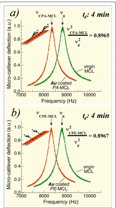
(C-MCL)/νo2 = (k(C-MCL)/m(C-MCL))/(ko/mo) will vary whenkor mchanges: an increase in mass will decrease this ratio, and an increase in the spring constant will increase this ratio. For the PA-MCL, Figure 2a shows the difference between its resonant frequency,νo, and its frequency after coating with its longitudinal direction parallel to the cone generatrix, frequencyν(CPA-MCL). It is apparent that resonant frequency changes after coat-ing, and the value of ν2(CPA-MCL)/νo2 is 0.8965. Figure 2b shows the corresponding results for the PE-MCL posi-tioned with its longitudinal direction perpendicular to the cone generatrix. The corresponding frequency ratio isν2(CPE-MCL)/νo2 = 0.8967. The measurements indicate that this ratio is equal for the two simultaneously Au-coated MCLs; the same shift in resonant frequency was detected. These first results suggest that no mechanical anisotropy was induced in the Au off-normal coated MCLs. Also, important evidence emerged indicating that the mass deposited on the PA-MCL was identical to that deposited on the PE-MCL. This last fact confirms that our system allows differential studies for both MCLs.
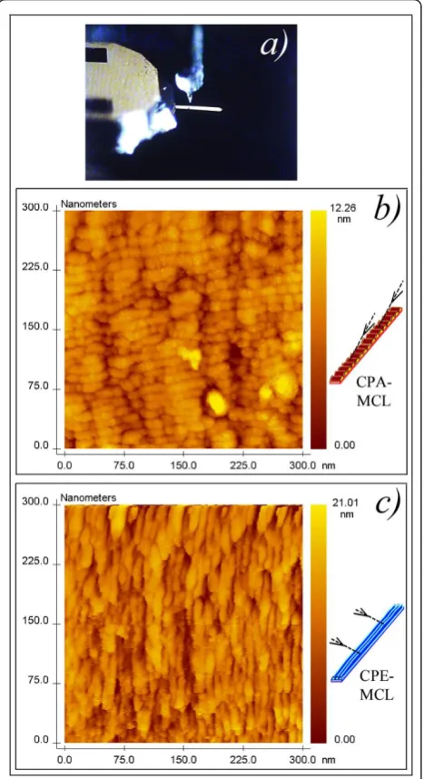
The results for the off-normal Co-coated MCLs are different to those for the Au -coated MCLs. Figure 3b shows the surface morphology of a Co-coated PA-MCL, demonstrating the generation of the transverse nano-strings. Figure 3c shows the surface morphology of a Co-coated PE-MCL with longitudinal nano-strings. The average width of the nano-strings was 12 nm. This nano-scale patterned was correlated with the elastic and mechanical properties of the MCLs, as shown in the next results.
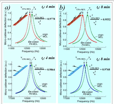
The top of Figure 4a shows the resonant frequencies of the PA-MCL: νo, before the coating process and
ν(CPA-MCL) after the coating process for a deposition
time t = 4 min. For this coated PA-MCL, the ratioν2
[image:3.595.306.539.86.505.2](CPA-MCL)/νo2 is 0.9778. The PE-MCL, simultaneously coated with the PA-MCL, also exhibited a shift in its resonant frequency such that ν2(CPE-MCL)/νo2 = 0.9864, as shown on the bottom of Figure 4a. Unlike the two Au-coated MCLs (for which the two ratios were equal: 0.8965 and 0.8967), these two simultaneously Co-coated
Figure 2 Resonant frequencies of two simultaneously Au coated MCLs: isotropic elasticity of the films.(a)Resonant frequency of an MCL before coating,νo, and the corresponding
frequency,ν(CPA-MCL)of the same MCL (now referred to as the
CPA-MCL) after 4 min Au coating and positioned with its longitudinal direction parallel to the cone generatrix.(b)Resonant frequencies for the MCL prior to coating and the same MCL (now referred to as the CPE-MCL) after 4 min simultaneous Au coating and positioned with its longitudinal direction perpendicular to the cone generatrix. Note that the same value of the ratioν2
(C-MCL)/νo2was measured for
MCLs exhibited different mechanical behaviour depend-ing on the position of the cantilever durdepend-ing the coatdepend-ing process; when the MCL was parallel to the cone genera-trix, the PA-MCL, the ratio was 0.9778, and when the MCL was perpendicular to the cone generatrix, the PE-MCL, the ratio was 0.9864. This effect remained when
the deposition time increased. Figure 4b shows the results when the two simultaneously coated MCLs were consecutively coated for other 4 min; that is, for a total deposition time of 8 min. Having demonstrated that the amount of material deposited onto each MCL was equal, we can remark that the spring constant of each Co-coated PA- or PE-MCL changed according to the longitudinal or transverse orientation of the film’s nano-strings.
Figure 5 shows the changes in the ratioν2(C-MCL)/νo2 with consecutive Co deposition times of 15 s. Ratios are displayed for both the PA-MCL and the PE-MCL. These results indicate that there is no difference between the PA- and PE-MCL with regard to these parameters until ≈1.0 min and that the same decrease occurs for both with time. The lack of difference may stem from the equal mass deposited on both MCLs and the equal k0 spring constants for both MCLs. No film was formed, only islands of Co were present and no change of thek0 of each MCL took place. After percolation, after≈ 1.2-1.4 min of deposition, the slope of the ratioν2(C-MCL)/
νo2 versus the deposition time, changed. The decrease in
ν2
(C-MCL)/νo2 produced by the increase in m was balanced out by the increase inkproduced by the per-colated film. Because the same quantity of material was deposited on the two simultaneously coated MCLs, the division of the value of ν2(C-MCL)/νo2 (starting at approximately 2.0 min) must has been a result of the newly generated nano-strings, which produced different values of kfor each MCL. In fact, the coated PE-MCL with longitudinal nano-strings exhibited a value of k higher than the corresponding value for the coated PA-MCL with transverse nano-strings.
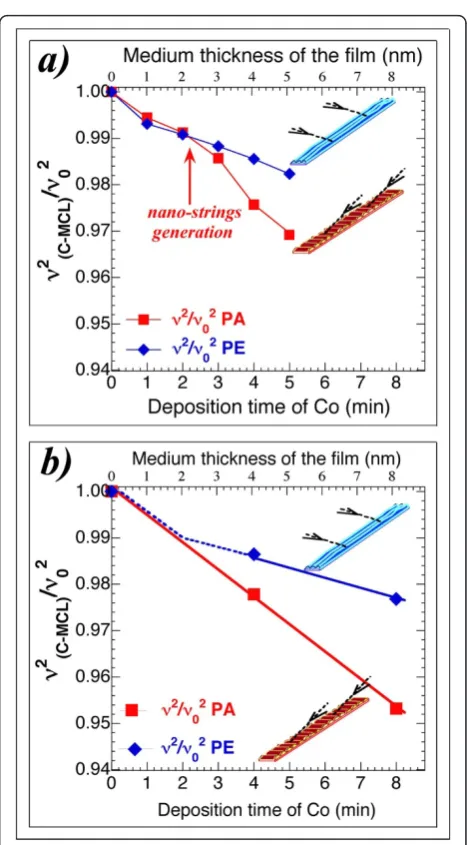
[image:4.595.58.292.90.519.2]At higher deposition times, when the nano-strings had begun to grow successfully, the difference between the mechanical behaviour of the simultaneously off-normal coated PA- and PE-MCLs increased, as shown in Figure 6. The changes in the ratio ν2(C-MCL)/νo2 with a Co con-secutive deposition time of 1.0 min (see Figure 6a) show how this ratio for the CPA-MCL (featuring the trans-verse nano-strings) has a slope practically equal to its initial slope and consistent with the increase in mass of the MCL. The slope for the CPE-MCL (with longitudi-nal nano-strings) is lower than the slope for the CPA-MCL, and because the increase in mass was equal for both MCLs, an increase in the value of the spring constant, k0, must have occurred for the CPE-MCL. One preliminary conclusion can be made: the off-nor-mal Co-coating process increased the spring constant of the MCL with longitudinal nano-strings, whereas for the MCL with transverse nano-strings, which was coated during the same process, only small changes of its spring constant occurred.
This behaviour was also observed for other two simul-taneously off-normal Co-coated MCLs with a consecu-tive deposition time of 4.0 min, as shown in Figure 6b.
Taking into account [16,17] that
ν0= (C2t/2πL2)(E0/12ρ0)1/2= 0.162(t/L2)(E0/ρ0)1/2 (1)
being C = 1.875 and the resonant frequenciesνo(in the interval (8665 ± 5) Hz), the density of the Si (r0 =
2.33 × 10³ kg/m3), the Si Young’s modulus (E0= 1.69 × 10¹¹ Pa), and the length (L = 450μm) and width (w= 50 μm) of the two MCLs in Figure 6a, the following values were deduced for MCL: mass, mo= 6.66 × 10⁻¹¹ kg,ko= 0.200 N/m and thicknesst= 1.7μm. The reso-nant frequency of a coated MCL is [16,17]:
ν2 C−MCL∼
[image:5.595.57.538.87.524.2]E0(wt/12) +Eδ{(w+ 2δ)[(1/2) + (δ/t) + (δ2/2t2)] +t/6} ρ0wt+ 2ρδ(w+t+ 2δ) (2)
Figure 4Resonant frequencies of two simultaneously Co coated MCLs: anisotropic elasticity of the films.(a)(Top) Resonant frequencies for the PA-MCL:νorepresenting the resonant frequency before the coating process andν(CPA-MCL)representing the resonant frequency after the
Co coating process with deposition timet= 4 min.ν2(CPA-MCL)/νo 2
= 0.9778. (Bottom) Resonant frequencies for the simultaneously coated PE-MCL:νorepresenting the resonant frequency prior to the coating process andν(CPE-MCL)representing the resonant frequency after the coating
process;ν2(CPE-MCL)/νo2= 0.9864.(b)Resonant frequencies of the two simultaneously coated MCLs coated consecutively for 4 min: that is, for a
total deposition time of 8 min.ν2(CPA-MCL)/νo2= 0.9532 andν2(CPE-MCL)/νo2= 0.9768. Note the significant difference between the PA-MCL and
where δis the thickness of the deposited Co film and
E its Young’s modulus. Considering that δ = 10 nm, thatt≈2000 nm, that w= 50000 nm and that the two MCLs are practically equal, we have approximated this last equation, resulting:
ν2
CPE - MCL/ν2CPA - MCL= (12E0+Elng)/(12E0+Etrs) = 1.025, (3)
with Elng and Etrs the Young’s modulus of the CPE film and CPA film, respectively, and 1.025 the experi-mental value of the MCLs in Figure 4b. Working from this last equation, we obtain the following:
Elng−Etrs= 0.3E0. (4)
Given the E0 value, this difference is ≈20% of the Young’s modulus of the micro-crystalline hcp bulk Co.
Conclusions
A specially designed homemade device combined with a PLD system allowed the off-normal simultaneous coating of two Si MCLs at different controlled locations with respect to the incidence plane of the plasma. For a fixed off-normal angle ofθ= 55°, two positions were used for the two MCLs: a position parallel to the incidence plane of the plasma and one perpendicular to that plane. The two off-normal Au-coated MCLs exhibited equal mechanical behaviour, indicating the in-plane isotropic elasticity of these Au pulsed-laser deposited films. This equal mechanical behaviour ensured that the amount of material deposited on both simultaneously coated MCLs
[image:6.595.305.539.82.505.2]was equal and made it possible to conduct a differential analysis between both. The two simultaneously off-normal Co-coated MCLs exhibited the following beha-viour. First, after percolation and nano-string generation, different mechanical behaviour occurred due to the increase in the spring constant for the MCL with Co nano-strings parallel to the longitudinal direction,
Figure 5Evolution of the ratioν2(C-MCL)/νo 2
[image:6.595.56.292.88.301.2]with a consecutive Co deposition time of 15 s. This ratio is shown for both the PA-MCL and the PE-PA-MCL. The percolation in the deposited Co over the MCLs was deduced for a total deposition time of≈1.2 to 1.4 min whenν2(C-MCL)/νo2changed its slope.
Figure 6Evolution of the ratioν2(C-MCL)/νo2with consecutive Co deposition times.(a)Evolution of the ratioν2(C-MCL)/νo2with a
consecutive deposition time of 1.0 min. This ratio for the CPA-MCL (featuring transverse nano-strings) has a slope that is practically equal to its initial slope and is consistent with the increment in mass of the C-MCL. This slope for the coated CPE-MCL (longitudinal nano-strings) is smaller than the slope for the CPA-MCL: an increase in the value of its spring constant,ko, must have occurred because
whereas the MCL with Co nano-strings transverse to the longitudinal direction experienced changes in the reso-nant frequency mostly produced by the increase in mass. Secondly, these results were connected with the anisotro-pic elastic behaviour of the Co film with nano-strings morphology. Thirdly, the Young’s modulus of the off-normal deposited Co film was 20% of the Young’s modu-lus of the bulk Co higher for the film direction parallel to the nano-strings than for the film direction transverse to the nano-strings.
Abbreviations
AFM: atomic force microscope; C-MCL: coated micro-cantilever; CPA: film deposited over the microcantilever parallel to the cone generatrix; CPE: film deposited over the microcantilever perpendicular to the cone generatrix; CPA-MCL: coated micro-cantilever parallel to the cone generatrix; CPE-MCL: coated micro-cantilever perpendicular to the cone generatrix; C(PA or PE)-MCL: coated micro-cantilever parallel to the cone generatrix or coated cantilever perpendicular: to the cone generatrix; MCLs: micro-cantilevers; Nd:YAG: neodymium-doped yttrium aluminium garnet; PA-MCL: micro-cantilever parallel to the cone generatrix; PE-MCL: micro-cantilever perpendicular to the cone generatrix; PLD: pulsed laser deposition; STM: scanning tunnelling microscopy.
Acknowledgements
This work was partially supported by the Spanish government under project MAT2007-66252.
Authors’contributions
VM, CF and JV participated from the beginning in devising the different steps of the work. Specially, VM with the preparation of the device for off-normal PLD, supports and microcantilever holders and during the coating processes. CF with mechanical characterization of microcantilever and subsequent determination of mechanical resonances. JV with the STM surface observation nano-strings of the microcantilever and VSM magnetic determinations. VM, CF and JV participated at the discussions and analysis of the results and during the preparation of manuscript. Specially CF dedicated extra time for this part.
Competing interests
The authors declare that they have no competing interests.
Received: 5 November 2010 Accepted: 12 April 2011 Published: 12 April 2011
References
1. Nix WD:Mechanical properties of thin films.Metall Trans A Phys Metall Mater Sci1989,20A:2217-2245.
2. Florando JN, Nix WD:A microbeam bending method for studying stress-strain relations for metal thin films on silicon substrates.J Mech Phys Solids2005,53:619-638.
3. Badawi KF, Villain P, Goudeau Ph, Renault PO:Measuring thin film and multilayer elastic constants by coupling in situ tensile testing with x-ray diffraction.Appl Phys Lett2002,80:4705-4707.
4. Yamaguchi T, Song W, Yamaguchi A, Yamamoto R:The anelastic study of Ag/Pd multilayers.J Alloys Compd1994,211-212:442-445.
5. Chen X, Vlassak J:Numerical study on the measurement of thin film mechanical properties by means of nanoindentation.J Mater Res2001,
16:2974-2982.
6. Danner R, Huebener RP, Chun CS, Grimsditch M, Schuller IK:Surface acoustic waves in Ni/V superlattices.Phys Rev B1986,33:3696-3701. 7. Mirkarimi PB, Shinn M, Barnett SA, Kumar S, Grimsditch M:Elastic
properties of TiN/(VxNb1-x)N superlattices measured lby Brillouin
scattering.J Appl Phys1992,71:4955-4958.
8. Craighead HG, Waggoner PS:Micro- and nanomechanical sensors for environmental, chemical, and biological detection.Lab Chip2007,
7:1238-1255.
9. Finot E, Passian A, Thundat T:Measurement of mechanical properties of cantilever shaped materials.Sensors2008,8:3497-3541.
10. McShane GJ, Boutchich M, Srikantha Phani A, Moore DF, Lu TJ:Young’s modulus measurement of thin-film materials using micro-cantilevers.
J Micromech Microeng2006,16:1926-1938.
11. Madurga V, Vergara J, Favieres C:Magnetic domain structures and nano-string morphology of laser off-normal deposited amorphous cobalt films with controlled magnetic anisotropy.J Magn Magn Matter2004, 272-276:1681-1683.
12. Madurga V, Vergara J, Favieres C:Surface nano-string morphology of oblique pulsed laser deposited cobalt thin films.International Conference TNT“Trends in Nanotechnology": 29 August-2 September 2005, Oviedo, Spain. 13. Madurga V, Vergara J, Favieres C:Soft magnetic nano-strings
simultaneously grown and sculpted on Si micro-cantilevers.J Magn Magn Matter2010,322:1519-1522.
14. Madurga V, Favieres C, Vergara J:Growth and sculpting of Co nano-strings on Si micro-cantilevers: magneto-mechanical properties.
Nanotechnology2010,21:095702-6.
15. Horcas I, Hernández R, Gómez-Rodríguez JM, Colchero J, Gómez-Herrero J, Baró A:WSXM: A software for scanning probe microscopy and a tool for nanotechnology.Rev Sci Instrum2007,78:013705-8.
16. Bishop RDE, Johnson DC:The Mechanics of VibrationCambrigde:Cambridge University Press; 1960.
17. Salvadori MC, Grown IG, Vaz AR, Melo LL, Cattani MC:Measurement of the elastic modulus of nanostructured gold and platinum thin Films.Phys Rev B2003,67:153404-4.
doi:10.1186/1556-276X-6-325
Cite this article as:Madurgaet al.:Generating and measuring the anisotropic elastic behaviour of Co thin films with oriented surface nano-strings on micro-cantilevers.Nanoscale Research Letters20116:325.
Submit your manuscript to a
journal and benefi t from:
7 Convenient online submission
7 Rigorous peer review
7 Immediate publication on acceptance
7 Open access: articles freely available online 7 High visibility within the fi eld
7 Retaining the copyright to your article