© 2016, IRJET | Impact Factor value: 4.45 | ISO 9001:2008 Certified Journal
| Page 1732
Analysis of Dynamic Performance of Three Phase Induction Motor
Using Matlab Simulation
Brahmananda Das
Asst.Prof.Department of electrical engineering
Koustuv group of institutions
Bhubaneswar,Odisha,India
[email protected]
---***---Abstract
This paper investigates the dynamicperformance of three phase induction motor by vector control method. The vector control algorithm is calculated on Motorola DSP56F80X. The block diagram is shown in figure which describes the structure of implement vector control algorithm. The result obtained is verified using matlab simulation. Initially speed reference is set at120 radian/s and torque taken as 0 nm. Then motor is run, speed, torque and current wave form is taken. Now speed reference changes to 160 radian/s and torque changes to 200nm and correspondence wave form is shown. I observed that it run smoothly over the full speed range, generate full torque at zero speed, and
have high dynamic performance including
fast acceleration and deceleration. It was originally developed for high-performance motor application for industrial drives. However, it is becoming increasingly attractive for lower performance applications as well due
to FOC's motor size, cost and power
consumption reduction superiority. .. In vector control method machine is control in a synchronously rotating frame where as in sinusoidal machine variables appears as D.C. quantities. In steady state current resolved in to two control inputs I. e. direct axis and quadrature axis component in a synchronously rotating reference frame, direct axis component act as field current and quadrature axis component act as armature current just like in D.C.Motors. For vector control direct axis components must oriented in the direction of rotor flux and quadrature axis components must perpendicular to it under all operating conditions .So vector control must ensure correct orientation of the space vector and generate control import signal. This develops closed loop control system .So that we can independently control flux & torque which provides fast dynamic performance like D.C.Motors.
Key Words: Clarke Transformation, PI controller ,park transformation, space vector modulation, vector control,
1.INTRODUCTION
This application note describes the design of a 3-phase
AC induction vector control drive. AC induction motors,
which contain a cage, are very popular in variable
speed drives. They are simple, rugged, inexpensive and
available at all power ratings. Progress in the field of
power electronics and microelectronics enables the
application of induction motors for high-performance
drives, where traditionally only DC motors were
applied. AC induction drives offer the same control
capabilities as high performance four-quadrant DC
drives. The drive application concept presented is that
of vector control of the AC induction motor running in
a closed-speed loop with the speed/position sensor
coupled to the shaft.
© 2016, IRJET | Impact Factor value: 4.45 | ISO 9001:2008 Certified Journal
| Page 1733
FOC
is
used
to
control
the AC synchronous and induction motors. It was
originally developed for high-performance motor
applications that are required to operate smoothly over
the full speed range, generate full torque at zero speed,
and have high dynamic performance including
fast acceleration and deceleration. However, it is
becoming increasingly attractive for
lower
performance applications as well due to FOC's motor
size,
cost
and power
consumption reduction
superiority.
2. Explanation:
The Park transformation has long been widely used in the analysis and study of synchronous and induction machines. The transformation is by far the single most important concept needed for an understanding of how FOC works, the concept having been first conceptualized in a 1929 paper authored by Robert H. Park. Park's paper was ranked second most important in terms of impact from among all power engineering related papers ever published in the twentieth century. The novelty of Park's work involves his ability to transform any related machine's linear differential equation set from one with time varying coefficients to another with time invariant coefficients
While the analysis of AC drive controls can be technically quite involved ("See also" section), such analysis invariably starts with modeling of the drive-motor circuit involved along the lines of accompanying signal flow graph and equations.
In vector control, an AC induction is controlled under all operating conditions like a separately excited DC motor. That is, the AC motor behaves like a DC motor in which the field flux linkage and armature flux linkage created by the respective field and armature (or torque component) currents are orthogonally aligned such that, when torque is controlled, the field flux linkage is not affected, hence enabling dynamic torque response. Vector control accordingly generates a three-phase PWM motor voltage output derived from a complex voltage vector to control a complex current vector derived from motor's three-phase
motor stator current input
through projections or rotations back and forth between the three-phase speed and time dependent system and these vectors' rotating reference-frame two-coordinate time invariant system. Such complex stator motor current space
vector can be defined in a (d,q) coordinate system with orthogonal components along d (direct) and q (quadrature) axes such that field flux linkage component of current is aligned along the d axis and torque component of current is aligned along the q axis. The induction motor's (d,q) coordinate system can be superimposed to the motor's instantaneous (a,b,c) three-phase sinusoidal system as shown in accompanying image (phases a & b not shown for clarity). Components of the (d,q) system current vector, allow conventional control such as proportional and integral, or PI, control, as with a DC motor.
© 2016, IRJET | Impact Factor value: 4.45 | ISO 9001:2008 Certified Journal
| Page 1734
forward vector control (IFOC), IFOC being more commonlyused because in closed-loop mode such drives more easily operate throughout the speed range from zero speed to high-speed field-weakening. In DFOC, flux magnitude and angle feedback signals are directly calculated using so-called voltage or current models. In IFOC, flux space angle feed forward and flux magnitude signals first measure stator currents and rotor speed for then deriving flux space angle proper by summing the rotor angle corresponding to the rotor speed and the calculated reference value of slip angle corresponding to the slip frequency. Sensor less control (see Sensor less FOC Block Diagram) of AC drives is attractive for cost and reliability considerations. Sensor less control requires derivation of rotor speed information from measured stator voltage and currents in combination with open-loop estimators or closed-loop observers
There are two vector control methods, direct or feedback vector control (DFOC) and indirect or feed forward vector control (IFOC), IFOC being more commonly used because in closed-loop mode such drives more easily operate throughout the speed range from zero speed to high-field-weakening. In DFOC, flux magnitude and angle feedback signals are directly calculated using so-called voltage or current models. In IFOC, flux space angle feed forward and flux magnitude signals first measure stator currents and rotor speed for then deriving flux space angle proper by summing the rotor angle corresponding to the rotor speed and the calculated reference value of slip angle corresponding to the slip frequency.
3. Vector control method:
3.1Description of vector control block diagram:
Figure-2[8]shows the basic structure of the vector control
of the AC induction motor. To perform vector control, it
is necessary to follow these steps:
• Measure the motor quantities (phase voltages and currents)
• Transform them to the 2-phase system (α,β) using a Clarke transformation
• Calculate the rotor flux space vector magnitude and position
• Transform them to the 2-phase system (α,β) using a Clarke transformation
the d-q coordinate system to the 2-phase system fixed with the stator
• Using the space vector modulation, the output 3-
Figure-1 Control Hierachy
phase voltage is generated
• Transform them to the 2-phase system (α,β) using a Clarke transformation
• Calculate the rotor flux space vector magnitude and position angle
• Calculate the rotor flux space vector magnitude and position angle
• Transform them to the 2-phase system (α,β) using a Clarke transformation
• Calculate the rotor flux space vector magnitude and position angle
• Transform them to the 2-phase system (α,β) using a Clarke transformation
• Calculate the rotor flux space vector magnitude and position angle
• Transform stator currents to the d-q coordinate system using a Park transformation
• The stator current torque (isq) and flux (isd) producing components are separately controlled
• The output stator voltage space vector is calculated using the decoupling block
• The stator voltage space vector is transformed by an inverse Park transformation back from
the d-q coordinate system to the 2-phase system fixed with the stator.
© 2016, IRJET | Impact Factor value: 4.45 | ISO 9001:2008 Certified Journal
| Page 1735
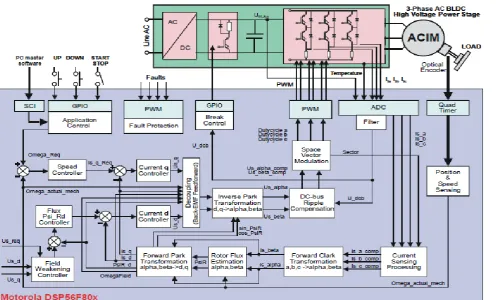
Figure-2 Block Diagram of Vector Control
3.2Forward
and
Inverse
Clarke
Transformation (a,b,c to
a b
and
backwards)
Figure-3 Clarke Transformation
The forward Clarke transformation converts a 3-phase system a,b,c to a 2-phase coordinate system alpha beta. Figure-3[6][7] shows graphical construction of the space
vector and projection of the space vector to the quadrature-phase components alpha beta.
Assuming that the a axis and the a axis are in the same direction, the quadrature-phase stator currents
© 2016, IRJET | Impact Factor value: 4.45 | ISO 9001:2008 Certified Journal
| Page 1736
For the non-power-invariant transformation the constant kequals k=2/3. In this case, the quantities isa and isa are equal. If we assume , the quadrature-phase components can be expressed utilizing only two phases of the 3-phase system:
Ta The inverse Clarke transformation goes back from a 2-phase (a,b) to a 3-phase isa, isb, isc system. For
constant k=2/3, it is given by the following equations
3.3 Forward and Inverse Park
Transformation (a,b to d-q and
backwards)
The components isa and isb, calculated with a Clarke transformation, are attached to the stator reference frame a, b. In vector control, it is necessary to have all quantities expressed in the same reference frame. The stator reference frame is not suitable for the control process. The space
Figure-4 Park Transformation
vector is rotating at a rate equal to the angular frequency of
the phase currents. The components isa and isb depend on time and speed. We can transform these components from the stator reference frame to the d-q reference frame rotating at the same speed as the angular frequency of the phase currents. Then the isd and isq components do not depend on time and speed. If we consider the d-axis aligned with the rotor flux, the transformation is illustrated in Figure-4[6][7], where is the rotor flux position.
The components isd and isq of the current space vector in d-q reference frame are determined by the following ed-quations
The components isd and isq of the current space vector in d-q
reference frame are determined by the following equations:
The component isd is called the direct axis component (flux producing component) and isq is called the quadrature axis component (torque producing component). They are time invariant and the flux and torque control with them is easy. To avoid using trigonometric functions on the DSP we
can directly calculate sinqField and cosqField using division. They are defined by the following
equations:
© 2016, IRJET | Impact Factor value: 4.45 | ISO 9001:2008 Certified Journal
| Page 1737
3.4
. Rotor Flux Model:
Knowledge of the rotor flux space vector magnitude and position is key information for the AC induction motor vector control. With the rotor magnetic flux space vector, the rotational coordinate system (d-q) can be established. There are several methods for obtaining the rotor magnetic flux space vector. The implemented flux model utilizes monitored rotor speed and stator voltages and currents. It is calculated in the stationary reference frame (a,b) attached to the stator. The error in the calculated value of the rotor flux, influenced by the changes in temperature, is negligible for this rotor flux model.The rotor flux space vector is obtained by solving the differential equations ,which are resolved into the a and b components. The equations are derived from the equations of the AC induction motor model.
3.5 Space Vector Modulation:
Space Vector Modulation (SVM) can directly transform the stator voltage vectors from a,b-coordinate system to pulse width modulation (PWM) signals (duty cycle values).
The standard technique of the output voltage generation uses an inverse Clarke transformation to obtain 3-phase values. Using the phase voltage values, the duty cycles needed to control the power stage switches are then calculated. Although this technique gives good results, the space vector modulation is more straightforward (valid only for transformation from the a,b-coordinate system).
The basic principle of the standard space vector modulation technique can be explained with the help of the power stage schematic diagram depicted in Figure-5[1]
Regarding the 3-phase power stage configuration, as shown in Figure-5, eight possible switching states (vectors) are feasible. They are given by combinations of the corresponding power switches.The graphical representation of all combinations is the hexagon. . There are six non-zero vectors, U0, U60, U120, U180, U240, U300, and two zero vectors, O000 and O111, defined in a,b coordinates.
© 2016, IRJET | Impact Factor value: 4.45 | ISO 9001:2008 Certified Journal
| Page 1738
means that the upper switch is OFF and the bottom switchis ON. These states, together with the resulting
instantaneous output line-to-line voltages, phase voltages and voltage vectors. SVM is a technique used as a direct bridge between vector control (voltage space vector) and PWM.The SVM technique consists of several steps: 1. Sector identification. 2. Space voltage vector
decomposition into directions of sector base vectors Ux, Ux±60
3. PWM duty cycle calculation
The principle of SVM is the application of the voltage vectors UXXX and OXXX for certain instances in such a way that the
F igure-5 space vector modulation
The principle of SVM is the application of the voltage vectors UXXX and OXXX for certain instances in such a way that the
“mean vector” of the PWM period TPWM is equal to the desired voltage vector. This method gives the greatest variability of arrangement of the zero and non-zero vectors during the PWM period. One can arrange these vectors to lower switching losses; another might want to approach a different result, such as center-aligned PWM, edge-aligned PWM, minimal switching, etc.
3.5 Application Description with hardware
Intgration:
The vector control algorithm is calculated on Motorola DSP56F80x. According to the user-required inputs, measured and calculated signals, the algorithm generates 3-phase PWM signals for an AC induction motor inverter. The block diagram of the ACIM control algorithm is shown in Figure6[8], which describes the structure of the implemented vector control algorithm (basic blocks and control signals).
The system incorporates the following hardware components:
• 3-phase AC induction motor with load coupled on the motor shaft
• 3-phase AC/BLDC high-voltage power stage
• DSP56F803EVM / DSP56F805EVM / DSP56F807EVM boards
• ECOPTINL, In-line optisolation box, which is connected between the host computer and the
DSP56F80xEVM
The drive can be controlled in two different operating modes
:• In the manual operating mode, the required speed is set by UP/DOWN push buttons and the drive is started
The system incorporates the following hardware components:
• 3-phase AC induction motor with load coupled on the motor shaft
© 2016, IRJET | Impact Factor value: 4.45 | ISO 9001:2008 Certified Journal
| Page 1739
• DSP56F807EVM boardsFigure -6 Hardware Integration
• ECOPTINL, In-line optisolation box, which is connected between the host computer and the
DSP56F80xEVM
The drive can be controlled in two different operating modes:
• In the manual operating mode, the required speed is set by UP/DOWN push buttons and the drive is started
and stopped by the RUN/ STOP swich on the EVM board
• In the PC remote
required speed is set by the PC master software bar graph and the drive is started and stopped by the START MOTOR and STOPMOTOR controls
Measured quantities:
• DCBus voltage
• Phase currents (Phase A, Phase B, Phase C)
• Power module temperature
• Rotor speed
The faults used for drive protection:
• “Overvoltage”
• “Undervoltage”
• “Overcurrent”
• “Overheating”
© 2016, IRJET | Impact Factor value: 4.45 | ISO 9001:2008 Certified Journal
| Page 1740
• “Wrong hardware”• “Overload”
Figure-7 Matlab simulink block diagram
4.1 Flux Calculation
© 2016, IRJET | Impact Factor value: 4.45 | ISO 9001:2008 Certified Journal
| Page 1741
4.2 Iq Calculation
4.3 Theta calculation
4.4 Dq to Iabc Conversion
4.6PWM Generation
© 2016, IRJET | Impact Factor value: 4.45 | ISO 9001:2008 Certified Journal
| Page 1742
4.7 Invertor With speed and current
calculation
4.8 current and speed waveform
© 2016, IRJET | Impact Factor value: 4.45 | ISO 9001:2008 Certified Journal
| Page 1743
5. Result Analysis
:
By varying the values of torque and speed I found a families of curves but due to limitation of this paper I can not attach all the characteristics curves. From those curves I found that when values of torque increases from 0 to 200 and speed increases from 120 to 160 and in next step torque increases from 200 to 400 and speed incres from 160 to 200 which is shown in characteristics curves.The electromagnetic torque suddenly increases to200 from 0, then it increases to 400 from 200 which is clearly shown from dynamic characterstics
Figure-8 for speed reference 120 radian/second and torque 0 nm.
Figure-9 signal scope for above torque speed
© 2016, IRJET | Impact Factor value: 4.45 | ISO 9001:2008 Certified Journal
| Page 1744
Figure-10 for speed reference 160radian/second and torque 200nm.
© 2016, IRJET | Impact Factor value: 4.45 | ISO 9001:2008 Certified Journal
| Page 1745
Figure-12 Dynamic characterstics when speed reference changes from 120 to 160 to 200radian/second and torque changes from 0 to 200 to 400 nm.
Conclusion
This paper demonstrates a direct vector control in an induction motor drive system. The proposed control method assures: Torque generating component and magnetic field – generating component have been controlled independently and gives. Good dynamic response. The transient response will be fast and dc machine like because torque control by does not affect the flux. Like a dc machine, speed control is possible in four quadrants without any additional control elements. Good stabilization of load torque for wide range speed control. At zero speed can able to produce full torque.It is developed using traditional PI controller,hence cost effective.Space vector modulationa reduces harmonics, so efficiency increases.It is very much cost effective for industrial drives which can replace all costly dc drives.This method also best suitable for high speed automotives.There is a large future scope for this area which can be developed using advanced controller. The effectiveness of the proposed control method is proved from above chracterstics curves.
References:
[1]
Zambada, Jorge (Nov 8, 2007). "Field-oriented control formotors". MachineDesign.com.
[2]
Jump up^ Bose, Bimal K. (June 2009). "The Past, Present,and Future of Power Electronics". Industrial Electronics Magazine, IEEE 3 (2): 11.doi:10.1109/MIE.2009.932709
[3]
Murray, Aengus (Sep 27, 2007). "Transforming motion:Field-oriented control of ac motors". EDN. Retrieved 11 May 2012.
[4]
.Holtz, J. (Aug 2002). "Sensorless control of induction motordrives" (PDF). Proceedings of the IEEE 90 (8): 1359–
1394.doi:10.1109/jproc.2002.800726. Retrieved June 3, 2012.
[5]
Jump up to: Zambada, Jorge. "The Benefits of FOC Sensorless Motor Control". Appliance Magazine. Retrieved June 3, 2012.[6]
Yano, Masao et al. "History of Power Electronics for MotorDrives in Japan" (PDF). p. 6, Fig 13. Retrieved 18 April 2012