ISSN: 1992-8645 www.jatit.org E-ISSN: 1817-3195
2359
TUNING PHYSICAL PARAMETERS FOR ENHANCED
RECEIVER PERFORMANCE OF PULSED-BASED
ULTRA-WIDEBAND IN SHORT RANGE
WIRELESS COMMUNICATIONS
1EZEDDIN SANAM, 2KAMARUZZAMAN SEMAN, 3MOHD ZALISHAM JALI
1,2,3
Faculty of Science and Technology, Universiti Sains Islam Malaysia, Bandar Bam 71800 Nilai, Negeri
Sembilan, Malaysia.
E-mail: [email protected], [email protected], [email protected]
ABSTRACT
Based on recent research about UWB communication, its clearly that one of the most interesting feature of the Pulse-based UWB technology is it’s high flexibility in term of the generated signal at the physical layer level. This feature combined with simple transceiver as it is almost digital communication structure allows this technology to be a good solution of different short-range wireless applications. This paper proposes enhancements on the receiver performance by tuning the most important physical parameters of the generated pulses as pulse modulations, coding and frame timing structure as these parameters are in great influences on the performance of the receiver. This performance can be defined as the probability of the lost packet in certain signal to noise ratio in varied distances and data rate scenarios. The method followed to validate the achievements of the enhancements of the receiver performance can be explained as proposing a communication link of certain pulse-based wireless system where at the beginning the physical parameters are set as reference parameters then the performance of the receiver measured. After that, tuning each parameter separately to check the enhancements of the receiver performance in certain different data rates an distances. Results showed that the performance can be enhanced significantly in term of the received signal errors for certain signal noise to power ratio with approximately up to 50% by tuning some physical parameters that have significant effects on received signal quality.
Keywords: Ultra Wideband, Time Hopping, Pulse Position Modulation, Physical Parameters, Signal to Noise Ratio, Bit Error rate.
1.
INTRODUCTIONUWB is recently been of great interest for short ranges wireless application due to its unique characteristics as a very short a train of pulses in ultra-wide bandwidth. Also, due to its very low duty cycle in comparison with classical narrowband , as significant reduction of power consumption can be achieved as the discontinuous emitted pulses consume much less [1]. This type of pulses can tuned to achieve different data transmissions [2]. As this technology considered carrier-less technology , modulation can be done by altering the pulses positions, amplitude or polarity. IR-UWB emitter can be designed without RF stage and this resulting in less power and receiver complexity [3,4]. All these advantages can be utilized for many short-ranges wireless application sharing the same
power and design constraints ( such as WSN and RFID) [5-7].
ISSN: 1992-8645 www.jatit.org E-ISSN: 1817-3195
2360 whereas in comparison, less works highlighted the physical layers parameters enhancements and how these enhancements can be utilized for better cross-layer design architecture of the IR-UWB wireless model [13-15]. The main motivation of this paper is to highlight the efficient selection of the physical parameters with their tuned associated values that allow the MAC layer to serve different requirements of distances and data transmissions. The proposed communication link of the IR-UWB in this paper, defined the generated signal parameters and how they can be tuned to manage the different requirements of distance and data transmission at the MAC layer. Reference receiver performance is determined by set of default parameters to generate the reference transmitted signal and then each parameters tuned separately with different possible values to detect and validate the performance enhancements by comparisons.
The main objectives of this research paper is to show the different enhancements can be achieved on the received time-hopping UWB signal by tuning its physical parameters can how this can be utilized for the proposal of cross-layer solution of the communication system.
The highlighted research questions in this research paper can be stated as the following: Fiestly; what are the parameters at the physical layer of time-hopping UWB communication system, that have the most influnces on the improvement of the received signal quality?!. Secondly; How the PHY and MAC layer can be interated and utilized in cross-layer time-hoppoing UWB architecture for adaptable solution that can serve different data rates and signal quality of service requirements ?!. Also, how to validate the proposed communication solution in baseband-level mainly in term of the probability of error received signal for certain signal noise to power ratio.
The structure of the paper is as follows: the follows section describes the generated referenced signal with all its related parameters and then, the receiver performance in term of BER for certain SNR is evaluated after tuning each of these parameters. These parameters include number of generated pulses, generated pulses per bit, pulses shaping factors, pulses modulations and pulses spreading spectrum techniques and finally the results are concluded and consideration for future extension is explained.
2.
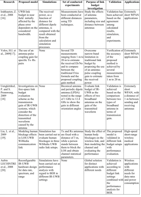
LITERATURE REVIEWAs a conclusions remarks from previous related studies of tenable pluse-based UWB proposed solutions, discussions are mainly focusing on methodology used to validate such proposals, and the efficiency of the suggested applications and the testbeds for implementations. Studies on UWB have highlighted different aspects of using wireless short-range communication systems, and optimal solutions for future scenarios. The purpose of the comparison presentation in the following Table 1 is to show the different analytical techniques used to validate the proposals of optimizing IR-UWB technique in short-ranges communication system.
Table 2 presents tunable IR-UWB proposed solutions in literature by highlighting their design methodologies for the reconfiguration aspects and capabilities. Also, the advantages and disadvantages of these proposals are indicated. Based on Tables 1 and 2, a complete system design for cross-layer communication modeling has not been developed yet to exhibit the flexibility of the system with various distances and data rate requirements. The performance of the proposed models needs to be evaluated for each budget link setting.
As a critical analysis based on previous presented studies, a dedicated test-bed design and implementation is required to glue all the puzzles for optimized IR-UWB solution. This includes system theoretical analysis, real-time signal simulation of the proposed model, and statistical analysis of the captured data in real short-range environments. This study aims to fill in the gaps left by previous works.
3.
PULSED-BASED UWB MODEL ANDPARAMETERS
The time hopping as spectrum spreading technique allowing multiple access performance with the M-ary Pulse Position modulation is considered due to its simplicity and suitability for simple wireless tags and sensors. The signal generated with time hopping (TH) with M-ary with pulse position modulation for K-th user can be mathematically modeled as [14]:
ISSN: 1992-8645 www.jatit.org E-ISSN: 1817-3195
2361 These parameters can be described as the following: P(t) represents the pulse shaping of the second derivative of Gaussian pulse with pulse
width . is the frame time and each frame is divided into time slots with duration time .
is the pulse shaping patterns, which is pseudorandom numbers with period , it represents the time hopping sequence for users. additional shift is required to avoid catastrophic collisions caused by the multiple access interference (MAI). The d parameter is the sequence for the data stream generated by the user after channel coding. is the shift introduced to modulate the pulse by M-ary PPM.
If it is assumed that the signal amplitude , for the M-ary PPM signal, then the equation (1) can be written as
.
These parameters of the generated referenced Pulse-Based UWB with its associated values can be summarized in the following Table 3.1.
Table 3: Generated Pulse-UWB with their associated values
Tunable IR-UWB Transmission Parameter
Description of the Parameter Average transmitted power
(Pow) in dBm unit
-30
Sampling frequency (Fc ) 50*10
Number of bits generated by the source
1000
Average pulse repetition (Ts) 3 *10 Number of pulses per bit (Ns) 1
Chip time (Tc) 1 *10
Cardinality of the TH code (Nh) 3 Period of the TH code ( Np) 2 Pulse duration (Tm) 0.5*10 Shaping factor for the pulse
(Tau) 0.25*10
Modulation techniques Binary-PPM
Channel models AWGN
The generated transmitted IR-UWB according to the parameter’s default values in Table-1- is shown in Figure 1.
Figure 1: Simulation of Generated Pulsed-Based UWB
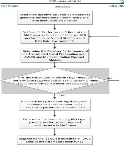
The following flowchart in Figure 2 summarizes the methodology followed in order to tune the PHY layer parameters according to certain performance requirements in MAC layer in cross-layer design solution as the PHY parameters tuned until met the criteria set by the MAC layer.
4.
RECEIVER PERFORMANCE WITHTUNABLE UWB GENERATED PULSES
The performance of the proposed tunable impulse-based UWB system is evaluated using BER criteria for different pulse shapes, coding, and signal timing structures. The physical parameters of the pulses are tuned to achieve different transmission rate requirements in various distance scenarios. Channel conditions of AWGN and IEEE 802.15.3a multipath fading channel models are considered in the simulation. System performance can be simplified as predetermined BER versus different data rate requirements in various distance scenarios.
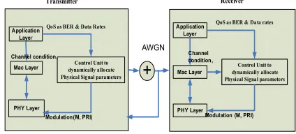
Pulses can be generated with different transmission rates depending on the pulse repetition interval (PRI), pulse modulation (M), and the number of generated bits (N). Therefore, the relationship between system design and evaluation can be defined as BER versus (PRI, M, N, and D) in different channel conditions. The proposed scheme can be illustarated in the following system architecture block diagram shown in Figure 3.
Application Layer
Mac Layer
PHY Layer
Control Unit to dynamically allocate Physical Signal parameters Transmitter
Application Layer
Mac Layer
PHY Layer
Control Unit to dynamically allocate Physical Signal parameters Receiver
+
AWGNQoS as BER & Data Rates QoS as BER & Data rates
Channel condition,
Modulation (M, PRI) Channel condition,
Modulation(M, PRI)
[image:3.612.314.524.64.184.2] [image:3.612.318.530.582.678.2]ISSN: 1992-8645 www.jatit.org E-ISSN: 1817-3195
[image:4.612.314.526.195.292.2]2362 The receiver performance of reference signal parameters (parameters listed in Table-1-) is considered a reference scenario to evaluate the different IR-UWB signal parameters. This performance is considered as a function of the BER for the certain value of the SNR over AWGN channel model as shown in Figure 4. The aim of such evaluation is to figure out the pulses parameters values that increases the transmission data rates and enhance the received signal performance in term of BER.
Figure 4: Receiver Performances of TH-PPM
Rake receiver performance of UWB for time hopped pulse position modulated signal propagating over a multipath channel is evaluated. Results show that the ARAKE (Ideal RAKE) receiver which processes all the multipath components and their contributions. The SRAKE ( Selective RAKE) contains eight multipath components and selects the multipath contribution which exhibit the best signal quality therefore, select the transmitted symbol based on the observation of this contribution only. The PRAKE (Partial RAKE) is the simplest receiver structure and it contains two branches. The selection process in this receiver consider only the first two multipath components, they arrive to the receiver.
The following results in figure 5 are obtained from a simulation using MATLAB to compare the performance of the five different RAKE structures. The BER performance can be enhanced significantly This can be shown in Figure-3 as a comparison between the value of BER = 〖10〗 ^(-1.9) in the case of ARAKE which processes multipath components and BER = 〖10〗^(-0.9) in case of SRAKE which processes only two multipath components. In this comparison also, the SRAKE, which processes eight components selectively, outperforms the PRAKE which process the eight randomly by almost 10% enhancement on the BER performance at SNR =9 dB. The complexity of the receiver using PRAKE is reduced
further; however, the performance of the receiver degrades significantly, particularly when the number of processed channel components is less. From this analysis it’s clearly seen that, in designing a tunable IR-UWB solution is important to choose a proper RAKE receiver structure with good trade-off between the receiver complexity and the BER applications requirements.
Figure 5: RAKE Receiver Performance: Ideal Rake (ARAKE), Selective Rake (SRAKE) and Partial Rake (PRAKE)
The effects of pulse repetition rates, widths, and shaping factors, as well as the modulations, are analyzed. Different numbers of bits generated at the source, as well as the numbers of pulses per bit, are analyzed using BER criteria to show the significance of each parameter. This analysis aids the design of the tunable IR-UWB transmission rates for different BER requirements and various distance communication scenarios.
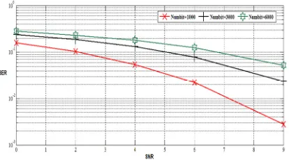
BER curve observations in Figure 6 show that the number of bits has a significant effect on the BER. As the number of generated bit increased from 1000 to 6000, the BER performance decreased from 10 . to 10 . for the same SNR = 9 dB. This is because as the number of bits increases; more bits are susceptible to noise so more errors can occur. Therefore, trade-off should be made when tuning the IR-UWB system based on the number of bits.
Figure 6: TH-PPM Receiver Performance with Different Numbers of Source Bits
0 1 2 3 4 5 6 7 8
10-3 10-2 10-1 100
SNR (dB)
B
E
[image:4.612.92.299.228.367.2] [image:4.612.315.522.589.704.2]ISSN: 1992-8645 www.jatit.org E-ISSN: 1817-3195
2363 By contrast, the BER performance is enhanced significantly as the number of pulses per bit increases as shown in Figure 7. As the number of pulses per bit increased by multiple of 6, the BER performance enhanced from (10 . 10 . for the SNR = 9 dB. Thus,an average BER of the system is proportional to the Number of Pulses. Therefore, the designer can make optimum trade-off between the numbers of pulses per bit requirements to transmission rates suitable for the propagation condition. This works provide contributions due to existing difficulties to make trade-off directly on the IR-UWB system with different transmission rates.
Figure 7: TH-PPM Receiver Performance for Pulses per Number of Pulses per Bit
Data transmission rates of the system depend on the period of repeated pulses. This pulse repetition period plays a significant role on BER performance. Figure 8, shows that the decrease in pulse repetition period from 8 x 10 s to 3 10 s enhances BER performance with BER at the same SNR of 9 dB from 10 10 . .. Therefore, BER performance shows enhancements as the pulse repetition interval decreases. This can be explained as the system is more susceptible to noise and interferences if the pulse repetition period is increases.
Figure 8: Effects of different average pulse repetition periods (Ts) on TH-PPM receiver performance
The generated bits per second can be defined as the reciprocal of code repetition rate Ns ( number of
[image:5.612.92.300.265.383.2]pulses per bits) multiplied by pulse average repetition period (Ts) . The selected values, shown in Table-2 present different data rate settings. It clearly shown that, the data rate depends mainly on the number of pulses (Ns) per bit and/or the average pulse repetition (Ts) parameters. The following table shows that the data transmission rate increases in case of fixed average pulse repetition period as 1 x 10 and number of bits fixed at 30000 bit but the pulse per bit are increased from 10000 pulses to 25000 pulses.
Table 4: Data Rate Calculations as Functions of Ts and Ns
Code repetition rate, Ns (Number of pulses per bit)
Frame time, Ts (Average pulse repetition period) in Seconds
Data rate = (Mbps)
Ns = 1/3 (NumPulse = 10000, Numbits
= 30000)
1 x 10 1
0.333 1x10
333 Mbps
Ns = 1/2 (NumPulse = 15000, Numbits
= 30000)
1 x 10 1
0.5 1x10
5000 Mbps
Ns = 2/3 (NumPulse = 20000, Numbits
= 30000)
1 x 10 1
0.666 1x10
666 Mbps
Ns = 25/30 (NumPulse = 25000, Numbits
= 30000)
1 x 10 1
0.833 1x10
833 Mbps
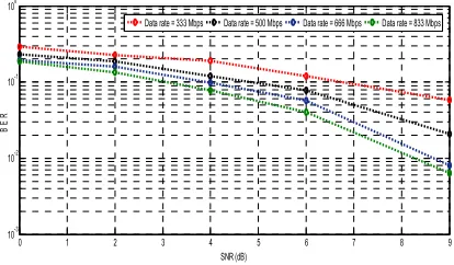
Figure 9 shows the effect of the increase in data rates on BER performance. As indicated by BER curves, decreased data rates result in a higher probability of bit error. The BER has improved by about 35% from 333 Mbps to 833 Mbps at the same SNR value of 9 dB.
Figure 9: Effect of different data rates on TH-PPM receiver performance
Parameters such as pulse shaping factors, timing, chip time, and shift time introduced by PPM and PAM modulations are analyzed. The purpose of this analysis is to determine whether the signal
0 1 2 3 4 5 6 7 8 9
10-5 10-4 10-3 10-2 10-1 100
SNR
B
E
R
Numpulses = 10000 Numpulses = 30000 Numpulses = 60000
0 1 2 3 4 5 6 7 8 9
10-3
10-2
10-1 100
SNR (dB)
B
E
R
Ts=3e-9
Ts=4e-9
Ts=8e-9
0 1 2 3 4 5 6 7 8 9
10-3 10-2 10-1 100
SNR (dB)
B
E
R
[image:5.612.314.521.535.656.2] [image:5.612.91.297.552.677.2]ISSN: 1992-8645 www.jatit.org E-ISSN: 1817-3195
2364 parameters related to specific modulation of PPM affect the performance of the average error probability. Figure 10 shows that the pulse shaping factor (which depends on pulse width) has minimum effect on BER performance. For the tunable TH-UWB system, the relative best BER performance can be achieved with the value of 0.5 x10 s of the pulse shaping factor (Tau).
Figure 10: Effect of pulse shaping factor on TH-PPM receiver performance
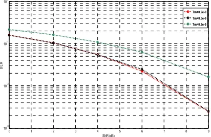
[image:6.612.314.522.84.232.2]Compared with the pulse shaping factor, the pulse duration factor Tm has a more significant effect on BER performance. Figure 11 shows that when pulse duration parameters are tuned into shorter values in nanoseconds of around 0.2 x 10⁻⁹ s, then BER performance is enhanced. It shows that the BER has been improved by about from 10 .! -10 . for pulse duration of 0. 9 ns to 0.2 ns at the same SNR value of 9 dB. This means that by a very small different in nanosecond of time, the BER has been shown to improve significantly because shorter signal duration, reduced the noise effect on the signal.
Figure 11: Effect of different pulse durations on TH-PPM receiver performance
[image:6.612.93.298.196.321.2]Change in chip time factor has minimum effect on BER performance, as shown in Figure 12.
Figure 12: Effect of different chip time (Tc) on TH-PPM receiver performance
The average transmitted power of the generated pulse has no significant effect on AWGN channel under the same communication scenarios and distances, as shown in Figure 13. This can be explained as the emitted UWB pulses is relatively considered very low power with very low duty cycle in comparison with the other narrow and wideband signals so, the emitted pulses can be considered with minimum interference with other signals.
Figure 13: Effect of different signal power on TH-PPM receiver performance
Time shifting introduced by PPM (dPPM) has relatively significant effect on BER performance. The values of dPPM tuned between 0.5 x 10 s and 0.7 x 10 s have minimum error probability, as shown in Figure 14. BER increased from 10 . to 10 .! s for the SNR =9 dB. The reason can be explained as increasing time shift introduced in the pulse position modulation of the time hopped UWB pulses decreases the signal self-interference as well as interferences with other signals. This finding can help the Impulse-based UWB designers to consider the proper value settings for the time shifting introduced for PPM modulation for minimum interference and enhanced BER Performance.
0 1 2 3 4 5 6 7 8 9
10-3 10-2 10-1 100
SNR (dB)
B
E
R
Tau=0.65e-9 Tau=0.9e-9 Tau=0.5e-9 Tau=0.8e-9
0 1 2 3 4 5 6 7 8 9
10-3 10-2 10-1
100
SNR (dB)
B
E
R
Tm=0.2e-9 Tm=0.5e-9 Tm=0.9e-9
0 1 2 3 4 5 6 7 8 9
10-3 10-2 10-1 100
SNR(dB)
B
E
R
Tc = 1e-9
Tc = 5e-9
Tc = 10e-9
Tc = 30e-9
0 1 2 3 4 5 6 7 8 9
10-3 10-2 10-1 100
SNR(dB)
B
E
R
Pow = -30 dB
Pow= -40 dB
[image:6.612.315.522.396.526.2] [image:6.612.92.298.518.652.2]ISSN: 1992-8645 www.jatit.org E-ISSN: 1817-3195
2365
Figure 14: Effect of different dPPM values on TH-PPM receiver performance
Modulation techniques are important factor on pulses design. Pulses modulations can be tuned for better BER performance and different data transmission rates. Evaluation of higher order M-PAM signal as well as M-PPM in term of BER for SNR from 5 to 9 dB is presented in Figure 15. The higher orders of M-PPM or M-PAM exhibit better performance over short-range wireless environments. PPM outperforms PAM with regard to the probability of symbol errors.
Figure 15: Receiver Performance for Different M-PAM and M-PPM Modulations
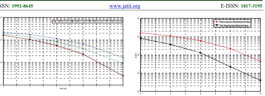
The effect of different spectrum techniques as sequence spreading or time hopping spreading also can be considered in designing tunable UWB pulsed-based solution. This can be shown by Figure 16 with scenario using the following parameters: fc = 50x10-9; dPPM = 0.5x-9; Ts = 3x10⁻⁹; numbit = 5000; and Numpulses = 5000.
Figure 16 clearly shows that BER performance of time hopped spreading of the pulses outperforms that of direct pulses spreading techniques as BER at SNR value of 9 shows BER improvement from10 ". 10 . . This finding may be attributed to the difference between Direct Sequence (DS) and Time Hopping (TH) spectrum spreading techniques especially for low-data-rate UWB pulses.
Figure 16: BER Comparison between DS and TH pulses Spreading Techniques
From all the previous BER simualtion analysis it is clearly that, the different pulses physical parameters can be designed and tuned with values for different data transmission rates and BER performance levels. Its clearly that from all above simulation results analysis that, some of these physical signal parameters have significant effects on BER such as modulation techniques and the binary order of the modulations, spectrum spreading techniques, the pulse duration factor that determine the pulse shaping, the number of generated pulses per pit and the time shifting introduced for pulse position coding ; with these BER improvements results and the proposed cross-layer system architecture of tunable time hopping the objectives of this study have been completed.
5.
CONCLUSIONS AND FUTURE WORKSIn this research, the main motivation is to investigate the effect of tuning the different parameters of pulses at the physical layer for time-hopped pulsed-based UWB communication system and determine the most effective paratmeters for enhanced recived signal performance. The Number of generated pulses , generated pulses per bit, pulses shaping factors, pulses modulations and pulses spreading spectrum techniques are the parameters of high impact of the performance of the UBW pulsed-based communication investigated in this paper. These parameters can be adjusted to meet the suitable requirements of signal quality and data rates. It clearly that tuning these parameters allows enhanced performance for certain scenarios and application requirements. The future extension of this work can be addressed as optimal UBW Pulse-Based Communication using genetic algorithm with fitness function can be chosen careful as weighing function for the three main variables of the communication requirements as BER for different distance and varied data-rates.
0 1 2 3 4 5 6 7 8 9
10-3
10-2
10-1
100
SNR (dB)
B
E
R
dPPM = 0.7e-9 dPPM = 0.5e-9 dPPM = 0.1e-9 dPPM = 0.8e-10
0 1 2 3 4 5 6 7 8
10-4 10-3 10-2 10-1 100
signal to noise ratio
B
E
R
[image:7.612.96.526.69.226.2] [image:7.612.91.298.374.504.2]ISSN: 1992-8645 www.jatit.org E-ISSN: 1817-3195
2366 This can be achieved by tuning the performance for exact predict performance based on previous statistical analysis of the performance and the required quality of the received signal.
REFRENCES:
[1] M. G. Di Benedetto. UWB communication systems: a comprehensive overview. Hindawi Publishing Corporation; 2006.
[2] J. R. Fernandes and D. Wentzloff, “Recent advances in IR-UWB transceivers: An overview”, Circuits and Systems (ISCAS), International Symposium on, Paris, 2010, pp. 3284-3287.
[3] H. Xu, and Yang, L. “Ultra-wideband technology: Yesterday, today, and tomorrow”, In Radio and Wireless Symposium, 2008, pp. 715-718.
[4] R. Hidayat, and Y. Miyanaga, “IR-UWB
pulse position modulation and pulse shape modulation through SV channel model”, In
Communication Software and Networks,
2010, 2010, pp. 214-217.
[5] Z. Zou, “Impulse radio UWB for the internet-of-things: a study on UHF/UWB hybrid solution”, Diss. KTH Royal Institute of Technology, 2011.
[6] Z. Zou, D. S. Mendoza, P. Wang, Q. Zhou, J. Mao, F. R. Zheng, “A low-power and flexible energy detection IR-UWB receiver for RFID and wireless sensor networks”, IEEE Transactions on Circuits and Systems, 2011, 58, pp. 1470-1482.
[7] H. Liu, M. Bolic, A. Nayak, I. Stojmenovic, “Taxonomy and challenges of the integration of RFID and wireless sensor networks”, IEEE network, 2008, vol. 22, pp. 26-35.
[8] V. Yajnanarayana, S. Dwivedi, A. De Angelis, P. Händel, Spectral efficient IR-“UWB communication design for low complexity transceivers”, EURASIP Journal on Wireless Communications and Networking 2014, vol. 158, pp. 1-13.
[9] M. Pezzin, I. Bucaille, T. Schulze, A. V. Pato, L. De Celis, “An open IR-UWB platform for
LDR-LT applications prototyping”,
Positioning, Navigation and Communication, 2009. WPNC 2009. 6th Workshop on 2009. [10] R. Chandra, H. Zhou, I. Balasingham, R. M.
Narayanan, “On the opportunities and challenges in microwave medical sensing and imaging”, IEEE Transactions on Biomedical Engineering, 2015, vol. 62, pp. 1667-1682.
[11] K. Thotahewa, J.-M. Redoute, M. R. Yuce,
“On medical implant communication of
IR-UWB”, International Conference on Body
Area Networks (pp. 26-31).
[12] A. Lecointre, D. Dragomirecu, R. Plana, “Software defined radio layer for IR-UWB systems in Wireless Sensor Network context”, Circuits and Systems, 2007.
[13] T. Wang, "Cross-layer design and optimization of short range wireless networks." PhD diss., University of Rochester, 2011.
[14] A. Lecointre, D. Dragomirescu, R. Plana, “Design and hardware implementation of a reconfigurable mostly digital IR-UWB radio”, Romanian Journal of Information Science and Technology, 2008, vol. 11, pp. 295-318. [15] R.F. Martin, “Ultra-wideband (UWB) rules
and design compliance issues”, In Electromagnetic Compatibility, 2003 IEEE International Symposium on 2003, vol. 1, pp. 91-96.
[16] Z. Irahhauten, J. Dacuña, G. J. Janssen, H. Nikookar, A. Yarovoy, L. P. Ligthart,
“analysis and modeling of near-field effects
on the link budget for uwb-wpan channels”,
IEEE International Conference
oncommunications, 2008,pp. 4872-4876.
[17] H. I. Volos, R. M. Buehrer, C. R. Anderson,
“A practical link budget for I-UWB systems”,
Vehicular Technology Conference, 2009.
VTC Spring 2009. IEEE 69th, 2009, pp. 1–5.
[18] L. Liu, X. Dong, Z. Tian, A. L. Schwartz, “link budget analysis and throughput measurement for multi-antennas wimedia UWB systems”, Vehicular Technology
Conference Fall (VTC 2009-Fall), 2009, pp.
1–5.
[19] A. Lecointre, D. Dragomirescu, R. Plana, “Design and hardware implementation of a reconfigurable mostly digital IR-UWB radio”, Romanian Journal of Information Science and Technology (ROMJIST) 2008, vol. 11, pp. 295-318.
[20] J. Li, B. Zhou, Y. Sun, W. Rhee, Z. Wang, “Reconfigurable, spectrally efficient, high data rate IR-UWB transmitter design using a Δ–Σ PLL driven ILO and a 7-tap FIR filter”, International Symposium on VLSI Design, Automation and Test,2011, pp.1,4.
ISSN: 1992-8645 www.jatit.org E-ISSN: 1817-3195
[image:9.612.69.524.108.741.2]2367
Table 1: Comparison of related studies on link budget analysis of IR-UWB
Research Proposed model Simulations Set of conducted
experiments
Purpose of link budget investigation
Validation Applications
Irahhauten, Z. et al., 2008 [16].
UWB link budget in near field initially affected by the phase error dependent on the considered bandwidth.
The received power, as a function of distance for different dipole antennas, is compared with the result obtained from the calculation and simulation processes. Measurements have been conducted at different distances using TD techniques.
Study the effects of antenna parameters, including size and distance between antennas
Validation has been achieved based on the agreement among calculated results, simulation, and experiments. Extremely short WPAN applications
Volos, H.I. et al., 2009[17].
The use of an antenna-pulse coupling gain for specific Tx–Rx pairs
None Several TD measurements ranging from 1 m to 20 m to estimate the received Eb/No and to compare between the traditional Friss formula and the proposed coupling gain method Overcome narrow-band limitation in traditional link budget by proposing the use of an antenna-pulse coupling gain to estimate the received power Verification of the accuracy of the proposed method is achieved by several measurements taken from 1 m to 20 m.
Extremely short WPAN applications
Uengkittikul, P. and S. Promwong, 2009 [18] Investigations on free-space link budget evaluation scheme as the transmission gain of IR-UWB systems, which consider the distortion of the transmitted waveform caused by the antenna
None Biconical antenna and periodic dipole antenna (LPDA) tested in the range of 1 GHz to 12.4 GHz to show the gain in different orientation angles
Evaluate link budget of IR-UWB as the effects of two broadband antennas on the gain of the transmitted waveform
Validation is achieved based on the comparison between two types of broadband antenna in terms of transmission gain. Extremely short WPAN, with a distance of 1 m between sending and receiving antennas
Liu, L. et al., 2009 [19].
Modeling human blockage effects in LOS UWB WiMedia communication link
Simulation has been carried out to evaluate human blockages in three WiMedia UWB radio link setups.
Tx and Rx antennas are fixed with a distance of 3 m, while a person stands between them to block the LOS and obtain channel statistical parameters.
Study the effect of human body blockages on the wireless link, and then modeling the channel and evaluating the performance The proposed model is validated in different link budget setups with performance evaluation. High-speed short-range wireless medical applications Aubin LECOINTRE et al., 2008 [20].
Reconfigurable IR-UWB hardware design for data rate, spectrum, and range
Simulations have been carried out as performance analysis with regard to BER in different IR-UWB settings
J o u r n a l o f T h e o r e ti c a l a n d A p p li e d I n fo r m a ti o n T e c h n o lo g y 1 5
th J
u n e 2 0 1 7 . V o l. 9 5 . N o 1 1 © 2 0 0 5 – o n g o in g JA T IT & L L S IS S N : 1 9 9 2 -8 6 4 5 w w w .j at it .o rg E -I S S N : 1 2 3 6 8 T a b le 2 : C o m p a ri so n o f re la te d s tu d ie s o n t u n a b le I R -U W B a t th e sy st em i m p le m en ta ti o n Authors Research title Reconfiguratio n Aspects Addressed Advantages
Aubin LECOINTRE et al., 2008
[16] Design and Hardware
Implementation of a Reconfigurable Mostly Digital IR-UWB Radio
A proposal for reconfigurable IR-UWB
implemented in field-programmable gate array
(FPGA) as proof of concept for reconfigurable data rates,
spectra, and ranges, The paper shows the
capabilities of reconfigurable parameters with low cost
IR-UWB transceiver design for spectrum occupation, radio range
and data rates. mainly to show transceiver consumed
power reduction for different architectures
design.
A. Lecointre et al., 2010 [17]
A Largely Reconfigurable Impulse Radio UWB Transceiver A proposal of an efficient
digital baseband architecture for reconfigurable IR-UWB transceiver. The capacity
for reconfiguration includes data rates, chip duration, pulse duration,
The author clearly defined some of the IR- UWB signal parameters tunable ranges to achieve
different data rates Author tried to highlight
the largest number of reconfigurable properties
architecture without clearly define the different data rates and
coverage ranges for different IR-UWB
Xia, L., 2008 [18]
Low Power Amplitude and Spectrum Tunable IR-UWB transmitter
A low power with reduced complexity carrier less transmitter with the ability to tune the spectrum. The buffer can be turned off between
pulse intervals to reduce power consumption. The A low-power, BPSK modulated impulse radio
UWB transmitter. The transmitter allows controlling the spectrum of the IR-UWB by tuning
the amplitude of the output impulses. power consumption of transmitter circuit at 100
MHz. There is no clear definition of the IR-UWB
Jun Li et al., 2011 [19] Reconfigurable, Spectrally Efficient, High
Data Rate IR-UWB Transmitter Design Using
a 7-Tap FIR Filter A prototype proposal for far infrared (FIR)
pulse-based UWB transmitter implemented in a 90 nm complementary metal–
oxide–semiconductor. The transmitter is a digitally reconfigurable The implemented circuit design showed high spectral and energy
efficiencies, spectral efficiency of this circuit design is limited to certain maximum pulse
rate also, the circuit require power
Marian Verhelst et al., 2008 [20]. A Low Power, Reconfigurable
IR-UWB System A proposal for a
complete UWB transceiver system
which is fully reconfigurable in terms of bandwidth, data rate, processing gain, and ranging
Low power communication and
ranging IR-UWB solution with possible
trade-off in term of data rates, processing
gain, acquisition protocols and ranging trade-off as the system performance improved by increasing number of pulses per bit (Ns)
[image:10.612.71.731.82.526.2]ISSN: 1992-8645 www.jatit.org E-ISSN: 1817-3195
2369
Determine the Physical Layer parameters to generate the Reference Transmitted Signal
with their Associated Values
Set Specific Performance Criteria at the MAC layer as Function of Receiver BER
performance in Varied Distances and Data Rate Environments
Determine the Receiver Performance of the Transmitted Signal Propagating over
AWGN and Multipath Fading Channel Models
Are the Parameters In the PHY layer meet the Performance requirements of BER in certain w ireless
Scenarios of varied Distances and Data rates ?
Tune each PHY parameter Separately until considerable enhancements in the receiver’s performance determined
Determine the best matching PHY layer parameters for certain required
performance in MAC layer
Regenerate the default transmitted IR - UWB after all the Parameters been tuned
Yes
[image:11.612.88.505.58.552.2]NO