3652
FORMALIZATION OF VERSIONING RULES FOR XML
SCHEMA USING UML CLASS DIAGRAM
1HANANNI AMAN, 2ROSZIATI IBRAHIM
1Department of Software Engineering, Universiti Tun Hussein Onn Malaysia (UTHM), MALAYSIA
2Department of Software Engineering, Universiti Tun Hussein Onn Malaysia (UTHM), MALAYSIA
E-mail: 1[email protected], 2[email protected]
ABSTRACT
In agile software development methodology, XML schema is used for developing the web applications. The major problem in using the agile software development methodology is capturing the software requirements especially when versioning occurred in XML Schema. This paper presents how to capture software requirements for document changes when versioning occurred in XML Schema. UML Class Diagram is used in addressing the versioning rules. Once the versioning rules are captured, these rules are then being formalized for better understanding of the versioning problem occurred in XML Schema.
Keywords: XML Schema, Versioning Rules, Traceability, UML Class Diagram, Document Changes
1. INTRODUCTION
XML is very popular in web community in sharing and transferring data between applications. The document and schema are multiplying and it needs to be maintained. Management of XML schema and document is very tedious and time consuming because of the XML nature itself. XML commercial tools offer editing XML document and schemas, specify validation in the document, organize and manage related files. Some tools assist with nice graphical interface, highlight validation error and view xml in tree structure. If any editing or updating of the file, every tool will keep the final editing as a file. However, any changes in XML schema or document cannot be traced after the file is saved.
Keeping changes is one of the important criteria in managing a file. The idea of keeping the changes in version concept arises when XML needs to keep track of the changes. This is because any changes occurred may change any requirements for the designer and end user. Hence the software developed based on it will have a different version. Software versioning is a process used in agile development to give unique names or numbers when changes occur in state of the software. The number assigned to the version is in increasing order within a given version number category based on major or minor new developments. Underlying of versioning process is how to handle any changes
occurred. Hence this paper addresses the issues of versioning rules. The rules for versioning are captured first. Class diagram is used to capture the changes occurred in XML Schema. Then the versioning rules are being formalized. The formal method is used for the formalization of versioning rules. The formal rules are then being tested using the case study to see the effectiveness of the versioning rules for the traceability link between the two class diagrams.
The rest of the paper is organized as follows: Section 2 is the related work regarding the research areas and Section 3 is the preliminaries discussion regarding the XML Schema and UML Class Diagram. Section 4 presents the versioning rules for the XML Schema and Section 5 discusses the formalization of the versioning rules. The case study is presented in Section 6 and finally, Section 7 is the conclusion of this paper.
2. RELATED WORK
3653 schema effect when a XML standard, XQuery is applied using a language called eXupdate [3]. Finally, keeping primitive changes of XML files is proposed by Brahmia et al. [4]. Their paper focused on Part 0 in W3C recommendation group. However, every change is based on the XML schema only. Any changes effect on conceptual level is not shown in previous research. Other researchers [5, 6] have seen the bigger picture of evolving and managing XML schema using class diagram change requirements. The change is on the conceptual model and makes the XML schema evolves and changes. However, forward direction does not show the reality of XML changes impact on conceptual models.
In software engineering area, more researchers focus on forward engineering of XML which is generating XML document from conceptual model [7, 8, 9, 10, 11, 12 and 13]. Forward engineering is a method to generate XML schema from conceptual model. However, research on generating conceptual model from XML application gain less focus. The reverse engineering for XML is also important as forward engineering because it is an alternative way to assist Agile developer generates conceptual models for communication and documentation purposes.
In software development process, XML schema modification needs to be maintained consistently by using the documentation method. The XML schema modification involves textual changes caused by the changes issue such as schema style changes [14], requirement changes [12, 7, 14, 15], adaptation to new XML technology [2], and integration with other XML schema [4]. The changes impact needs to be understood by end users, designers and software developers. Therefore, this paper addresses the issue of changes in XML documents by formalizing some of the important rules for document versioning (that is when changes occurred). To see the effectiveness of the versioning rules, a case study is also presented in this paper for evaluation of the versioning rules.
3. PRELIMINARIES
This section describes two important factors in formalizing the versioning rules: XML Schema and UML Class Diagram. The XML Schema is used to address the versioning rules in web applications. UML Class Diagram is used for traceability link to detect document changes for XML Schema. XML Schema and Class Diagram are used to formalize the versioning rules. Versioning occurs when there are changes in a
XML schema based from the previous XML schema.
2.1 XML Schema
XML Schema is used for developing web applications. It has rigorous specification of XML document. XML schema consists of rules that define the constraint of each element in the XML document which provide a mean for defining the structure, content and semantics of XML documents in more detail [16]. If any element and attributes in XML document satisfy the constraint in the schema, a valid report will be generated.
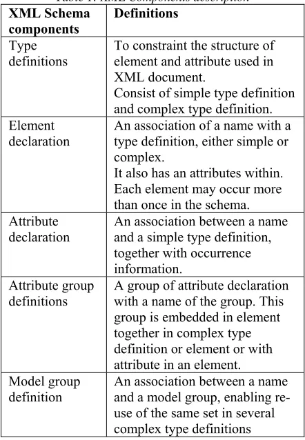
[image:2.612.307.528.331.650.2]XML schema consists of 5 components [16, 17]. They are type definition, element declaration, attribute declaration, attribute group definition and model group definition. Table 1 gives the definitions of XML schema components.
Table 1: XML Components description
XML Schema
components Definitions
Type definitions
To constraint the structure of element and attribute used in XML document.
Consist of simple type definition and complex type definition. Element
declaration
An association of a name with a type definition, either simple or complex.
It also has an attributes within. Each element may occur more than once in the schema. Attribute
declaration
An association between a name and a simple type definition, together with occurrence information.
Attribute group definitions
A group of attribute declaration with a name of the group. This group is embedded in element together in complex type definition or element or with attribute in an element. Model group
definition
An association between a name and a model group, enabling re-use of the same set in several complex type definitions
3654
Person
- lastname - firstname
+ SetName + GetName
FocusGroup
- staffid
- EvaluateForm
PostGraduateStudent
- matrixno
PgForm
- detailinfo
+ GetForm + Submit + View + Evaluate
- FillUpForm <?xml version="1.0" encoding="utf-8"?>
<schemaxmlns:xs="http://www.w3.org/2001/XM LSchema">
<element name="book"> <complexType> <sequence>
<element name="title" type="xs:string"/>
<element name="author" type="xs:string"/>
<element name="character" minOccurs="0" maxOccurs="unbounded">
<complexType> <sequence>
<element name="name" type="xs:string"/>
<element name="friend-of" type="xs:string" minOccurs="0"
maxOccurs="unbounded"/>
<element name="since" type="xs:date"/>
<element name="qualification" type="xs:string"/>
</xs:sequence> </xs:complexType> </xs:element>
</xs:sequence> <xs:attribute name="isbn" type="xs:string"/>
[image:3.612.90.304.81.463.2]</xs:complexType> </xs:element> </xs:schema>
Figure 1: Example Of XML Schema
Based from Figure 1, the 5 components in XML Schema are used using the tagging. The XML Schema shows that one element named <book> contains attribute named <isbn> with string type. Other element named <title>, <author>, and <character> is nested in the <book> element. Each <title> and <author> element has string type. While <character> element has a set of element named <name>, <friend-of>, <since> and <qualification> nested with it. <name>, <friend-of> and <qualification> element also use string type. Meanwhile, <since> element uses date type. <character> element may occur within <book> element either no element or maximum unbounded. Occurrences for other element that nested to <book> element, which is <title> and <author> occurs once only. <friend-of> element occur either no element or maximum unbounded relate to <character> element. Based on this example, XML Schema can be understood easily. However using this format of the XML Schema
presentation is difficult for the user to review the contents of the application.
2.2 UML Class Diagram
UML (Unified Modelling Language) [18] Class Diagram is used during design phase of software development life cycle (SDLC). Under SDLC four main phases are used when developing any software or system. They are analysis, design, implementation and testing. During design phase, software specification will be developed using UML. UML specified 12 diagrams which include use-case diagram, class diagram and others.
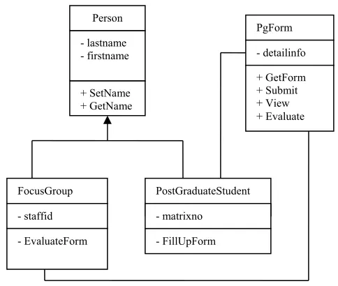
The class diagram is the main static analysis diagram [18]. It shows the static structure of the model for the classes and their relationships. They are connected to each other as a graph. Each class has its own internal structures and its relationships with other classes. Figure 2 shows an example of a class diagram for Monitoring System of Postgraduate Students.
Figure 2: A Class Diagram For Monitoring System Of Postgraduate Student
Based from Figure 2, classes FocusGroup and
PostGraduateStudent are subclasses from class
Person. Class PgForm has 4 functions (GetForm,
Submit, View and Evaluate). Further details
[image:3.612.325.567.372.577.2]3655 Traceability
Link
4. THE VERSIONING RULES (VR)
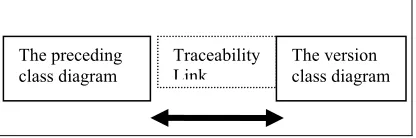
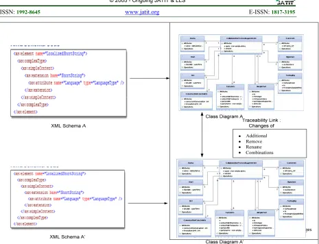
[image:4.612.313.522.131.249.2]As stated earlier in this paper, changes occurred in XML documents need to be understood and documented. The issue of changes in XML documents is addressed by using the versioning of the XML documents. If XML document changes, it implies that the versioning occurs. Therefore, to address the versioning issue, two class diagrams are used from XML schemas for versioning purposes. The earlier XML Schema is used to generate a class diagram called preceding class diagram. When maintenance process occurs, new XML schema is introduced. This new XML schema has been modified because of the number of XML schema components have been changes. The changes are visible in syntax. In order to capture the semantic changes of the new schema, the new schema need to be transformed into class diagram. The same transformation is used to generate the preceding class diagram. The modified preceding class diagram is now called a version class diagram. The version class diagram needs to be compared with preceding class diagram to capture the additional, removal and rename of class diagram components. Figure 3 shows the scenario of this.
Figure 3: Traceability Link Between Two Class Diagrams
[image:4.612.91.299.406.475.2]Based from Figure 3, a single change of XML schema impacts the specification of the requirement document too. The manual update of requirement changes is tedious and laborious. Therefore, when XML schema’s new version is introduced, the requirement document needs to be updated. When requirement changed, number of classes in version class also changed. In this research, a class is changed when number of version classes is more than classes in preceding class diagram. Figure 4 shows the versioning occurred between two XML Schemas. Therefore, in order to detect the changes between two class diagrams, few steps are performed for traceability factor. Table 2 shows the three steps performed based from traceability link in Figure 4.
Table 2: Changes Detection In Class Diagrams
Changes Details
Step 1 Each class of both class diagrams has been compared - level by level of the diagrams.
Step 2 Each Added classes and Removed classes are compared.
Step 3 Classes which have the same attribute and same relationship are tested with string similarity. High result of similarity tests the changes of new versions of class diagram.
Based from Table 2, the modification is generated by three (3) atomic operations classified which are additional, removal and rename operations of XML basic components (element, attribute, type definition, model group and attribute group). An additional change involves in adding any element or attribute in the schema whereas a removal change involves any removing element of XML components. Beside of that, rename operation occurs when an element’s name is given new name and maintain the set of attributes and relationship. A rename operation involves only one (1) class that has been renamed. Combination operation involves combinations of these three (3) atomic operations. These combinations will generate new semantic changes such as migration of element to another element where involves removal and additional at different level of class diagram. But in this research, a new kind of semantic changes is proposed. The proposed combination changes occur when a removed element from preceding class diagram is added by two (2) new elements which maintain the same set of attribute and relationship as the removal element. This link is called as traceability link.
In order to show the new combination of atomic operations, the Versioning Rules (VR) is introduced. It involves additional, removal, rename and combination of these operations on element. Tracing changes operations occur on class diagram as class diagram represents semantic changes of XML schema versioning.
Versioning Rule 1:
There are two (2) class diagrams that need to be transformed from XML schemas for versioning. The new version is a subset of preceding schemas. The newer versions has maintained some of classes, attributes, relationship from the preceding class diagram, moreover new classes are added and some classes are removed.
The preceding
3656
Versioning Rule 2:
The traceability factor incurred when:
A class has been added in new version class diagram.
A class has been removed in new version class diagram.
ONE (1) class that has been removed from preceding schema then has been added with more than TWO (2) new similar classes name.
The new added classes must have the same attributes set and association source as preceding removed class.
The two versioning rules are important to capture the changes occurred in XML Schema. Note that the document changes in XML Schema are captured thru class diagrams. These versioning rules are then being formalized and described in the next Section.
5. FORMALIZATION OF VERSIONING RULES (VR)
In order to formalize the versioning rules, we need formal definitions of class diagram and transformation rules. These formal definitions are already presented in our previous paper in [20]. For consistency, we presented part of it here in order to establish the versioning rules formula.
Rule 1: Class diagram consists of: Class
Relationship
where
Class is consists of a set of attributes and each attribute may have multiplicity.
Relationship is a connection between classes. Each association may have multiplicity. There are three (3) kinds of relationships which are association, aggregation and dependency.
o Association is a connection between
classes that relates.
o Aggregation is a connection between
classes where a class has to be a part of other class.
o Dependency is a connection between
classes where a class are dependent on other class.
The formal definition of class diagram is as follow:
Definition 1: Let “cd” be a class diagram. “cd” consists of a finite set of classes and a finite set of relationships. Thus, class diagram can be defined as
; (1) where
The class has a set of attribute and attribute’s type. Each attribute has a multiplicity value to show the number of occurrences appear in each class. The class definition is illustrated in Definition 2.
Definition 2: Let “cls be classes consist in a class diagram. The class consists of a finite set of attribute and relationship of a class. Thus class can be defined as
(2)
where
is a set of attributes of class
and
denoted to type of attribute, of a class, with a multiplicity value
where “multiplicity” be a multiplicity of classes or attribute.
Multiplicity consists of value to show the number of minimum and maximum occurrences of association class or attribute in each class. Thus multiplicity can be defined as
Classes relationship is defined as “assoc” where each “assoc” may has one of these values, which are association, aggregation and dependency as stated in Definition 3.
Definition 3: Let “assoc” be an association between classes. Thus it can be defined as unary relationship of class.
where
3657
Definition 4. Let “cdv” be a version of preceding class diagram, “cd”. “cdv” has more number of classes than classes of preceding class diagram, “cd”. Thus, cdv can be defined as
(4) where
Based on Definition 4, versioning rules are defined. Versioning rules define a traceability factor by comparing two class diagrams. Changes will be recognized as added when there are new class in version class diagram and removed class when there are missing class in version class diagram. The versioning rules are shown in VR1, VR2 and VR3.
VR1. Let “ ” be an added factor of class
diagrams where a new class, “ ” is found in
version class diagram, “cdv” as compare with class diagram, “cd”. Thus
(5)
VR2. Let “ ” be a removed factor of class
diagrams where class, “ ” is missing in version
class diagram, “cdv” as compare with class diagram, “cd”. Thus
(6)
The removed class will be the target of next changes detection. VR1 is used for the rule where the change detection steps are listing the added classes on new version of class diagram and VR2 is used when the listing are removed from the removed classes from preceding class diagram, where two (2) added classes must relate with one (1) removed class. The related components between class diagrams are classes and versioning criteria are assoc and attribute which are presented in VR3.
VR3. Let “ ” be a traceability factor of
class diagrams where a classes,“ ” and “ ”
of version class diagram, “cdv” is evolved from a
class, “ ” of preceding class diagram, “cd” if
“ ” and “ ” of version class
diagram, “cdv” has the same “ ”of
preceding class diagram, “cd” and “ ”
and “ ” of version class diagram,”cdv”
is the same with “ ” from preceding
class diagram,”cd”. Thus,
(7)
where
Based from the versioning rules (VR1, VR2 and VR3), any changes detected in version class diagram from preceding class diagram will be marked and traceability factor will become 1 (one). If there are no changes, then the traceability will be 0 (zero).
Under SDLC, the next step after formal specification is implementation phase. We implement the tool based on the formal rules for these versioning rules and transformation rules [20]. The rules are embedded within the tool to make the detection of changes easier. The details of the tool named XML-DocTracker can be found in [21]. The purpose of implementing the SML-DocTracker is to being able to generate Software Requirements Specification (SRS) automatically from the XML Schema.
6. A CASE STUDY
In this section a case study is presented to show how the versioning rules are being used for the traceability link and to generate software requirements for document changes. The transformation rules are used from [22].
cpp-3658 cpa-2_0.xsd for version 2 [23]. ebXML is an open specification of XML based infrastructure which provide global use of electronic business information for an interoperable, secure and consistent manner sponsored by Organization for the Advancement of Structured Information
Standards (OASIS) and UN/CEFACT.
UN/CEFACT is an organization that makes International Electronic Data Interchange (EDI) standards for electronic trade documents in XML format [23].
Table 3 shows the number of components used between two (2) versions of ebXML schema. This design allows reuse of both elements and types. The design benefits the high reuse of class. However, this kind of schema is difficult to read and understand. The difficulties make this case study suitable to address the versioning problems.
Table 3: Ebxml Schema Component Analysis
XML schema
component Cppa schema Cpp-cpa-2.0 schema
Global Element 40 55
Global Attribute 4 4
Local Element 10 8
Global Complex Type
2 5
Global Simple Type
6 9
Group Model 0 0
Attribute Group 2 2
Element with Ref 43 53
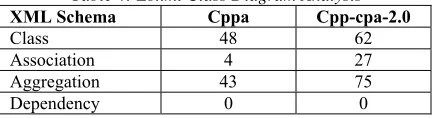
[image:7.612.86.302.558.617.2]From Table 3, the XML schemas are used to generate the class diagrams. Table 4 shows the analysis for the two class diagrams from the earlier XML Schema version (Cppa) and the later version (Cpp-cpa- 2.0).
Table 4: Ebxml Class Diagram Analysis
XML Schema Cppa Cpp-cpa-2.0
Class 48 62
Association 4 27
Aggregation 43 75
Dependency 0 0
Table 4 shows the number of components used between two (2) versions of ebXML schema. This design allows reuse of both elements and types. The design benefits the high reuse of class.
We then used this case study to evaluate the XML-DocTracker [21] for its effectiveness in tracking the changes. The evaluation of XML-DocTracker is compared with Necasky in [11]. XML Schema components of both schemas are transformed based on reverse transformation rules [22] using XML_DocTracker tool [21]. As for evaluation, this reverse method is evaluated and compared with [11]. The evaluation results are shown in Table 5.
Table 5: Comparison Of Evaluation Of Two Methods XML_DocTracker
[21] Necasky [11]
XML
Schema Cppa Cpp-cpa-2.0 Cppa Cpp- cpa-2.0
Class 48 62 45 53
Association 4 27 0 0
Aggregation 43 75 n/a n/a
Dependency 0 0 n/a n/a
Based from Table 5, it is shown that XML-DocTracker is able to transform more classes with aggregation relationship. This more specific relationship is then being used for generating the new Software Requirements Specification [21]. Note that in earlier research done by Necasky [11], the limitations occurred for aggregation and dependency. They do not address aggregation and dependency issues. Our research added these two issues in tracking the changes in XML Schema.
7. CONCLUSION AND FUTURE WORK
In this paper, we have presented a formalization of versioning rules for XML Schema using class diagram. The versioning rules are used for traceability factors in order to detect document changes in XML Schema. The changes of XML documents are not easy to keep track manually. Therefore, giving the versioning rules for the XML document changes help to solve the document changes issue. However, since the informal rules of versioning rules do not have formal definition, we formalized the rules for better understanding.
The tool named XML-DocTracker has been implemented based on the transformation rules and versioning rules in order to regenerate the documents (Software Requirements Specification) from the XML Schema.
3659
ACKNOWLEDGEMENTS
The authors would like to thanks Malaysian Ministry of Higher Education (MoHE) for supporting this research under the Fundamental Research Grant Schema (FRGS).
REFRENCES:
[1] Tan, M., & Goh, A. (2004). Keeping Pace with Evolving XML-Based Specifications, 280–288.
[2] Cavalieri, F., Guerrini, G., & Mesiti, M. (2011). Updates on XML documents and schemas. 2011 IEEE 27th International Conference on Data Engineering Workshops, 308–311. doi:10.1109/ICDEW.2011.5767672 [3] Cavalieri, F. (2010). E X up: An Engine for
the Evolution of XML Schemas and Associated Documents. In EDBT Workshop Proceedings.
[4] Brahmia, Z., Grandi, F., Oliboni, B., & Bouaziz, R. (2012). Versioning of Conventional Schema in the tXSchema Framework. 2012 Eighth International Conference on Signal Image Technology and Internet Based Systems, 510–518. doi:10.1109/SITIS.2012.153
[5] Klímek, J., Maly, J., Mlynkova, I., & Necasky, M. (2012). Evolution and change management of XML based system. Journal of Systems and Software, 85, 683–707. doi:10.1016/j.jss.2011.09.038
[6] Polák, M., Necasky, M., & Holubová, I. (2013). DaemonX: Design , Adaptation , Evolution , and Management of Native XML. In IIWAS ’13: Proceedings of International Conference on Information Integration and Web-based Applications & Services (p. 484). doi:10.1145/2539150.2539159
[7] Domínguez, E., Rubio, Á. L., Lloret, J., Pérez, B., & Rodrı, Á. (2011). Evolution of XML schemas and documents from stereotyped UML class models : A traceable approach. Information and Software Technology, 53, 34–50. doi:10.1016/j.infsof.2010.08.001 [8] Fong, J., Cheung, S. K., & Shiu, H. (2008).
The XML Tree Model – toward an XML conceptual schema reversed from XML Schema Definition. Data & Knowledge
Engineering, 64(3), 624–661.
doi:10.1016/j.datak.2007.10.004
[9] Franceschet, M., Gubiani, D., & Montanari, A. (2013). A Graph-Theoretic Approach to Map Conceptual Designs to XML Schemas. ACM Transactions on Database Systems (TODS), 38(1), 6.
[10] Haitao, C. (2010). A Survey to Conceptual Modeling for XML. Proceedings 2010 3rd International Conference Science and Information Technology, 8, 473–477.
[11] Necasky, M. (2009). Reverse Engineering of XML Schemas to Conceptual Diagrams. In Proceedings 6th Asia PAcific Conference on Conceptual Modelling (Vol. 96, pp. 117– 128).
[12] Al-Kamha, R. (2007). CONCEPTUAL XML FOR SYSTEMS ANALYSIS. Brigham Young University.
[13] Weidong, Y., G. Ning, G. and Baile, S. (2006). "Reverse Engineering XML," Computer and Computational Sciences, 2006. IMSCCS '06. First International Multi-Symposiums on, vol. 2, pp. 447- 454.
[14] Amavi, J., Chabin, J., Ferrari, M. H., & Pierre, R. (2014). A ToolBox for Conservative XML Schema Evolution and Document Adaptation, 299–307.
[15] Malý, J., Necasky, M., & Mlýnková, I. (2012). Efficient adaptation of XML data using a conceptual model. Information System
Front.
http://doi.org/10.1007/s10796-012-9375-8.
[16] XML Schema Part 0 : Primer 2nd Edition.
(2004). Retrieved from
http://www.w3.org/TR/2004/REC-xmlschema-0-20041028/
[17] XML Schema Part 1: Structures 2nd Edition.
(2004). Retrieved from
http://www.w3.org/TR/2004/REC-xmlschema-1-20041028/
[18] Miller G. (2003). What’s New in UML 2.0, A
Borland White Paper,
http://www.borland.com/
[19] Rosziati Ibrahimi (2009) An introduction to object-oriented programming with UML using
Borland C++. Penerbit UTHM, Universiti
Tun Hussein Onn Malaysia. ISBN 9789832963776.
[20] Aman, H., Ibrahim, R. (2014). Formalization of Transformation Rules from XML Schema to UML Class Diagram. International Journal of Software Engineering and Its Application, 8(12), 75–90.
3660 [21] Aman, H., Ibrahim, R. (2017).
XML-DocTracker: Generating Software Requirements Specification (SRS) from XML Schema. ICISS 2016 - 2016 International Conference on Information Science and Security, art. no.7885872, DOI: 10.1109/ICISSEC.2016.7885872
[22] Aman, H., Ibrahim, R. (2015). XML schema reverse transformation: A case study. Lecture Notes in Computer Science (including subseries Lecture Notes in Artificial Intelligence and Lecture Notes in Bioinformatics), Part IV 9158, pp. 575-586. doi: 10.1007/978-3-319-21410-8_44
3661
[image:10.612.91.556.61.417.2]