A TEMPERATURE AWARE Z-CURVE BASED ONLINE
TASK PLACEMENT ALGORITHM FOR PARTIALLY
RECONFIGURABLE FPGA
s
1SENOJ JOSEPH, 2 Dr. K.BASKARAN
1
Assistant
Professor, Department of ECE, Sri Krishna College of Technology, Coimbatore, India.
2
Associate Professor, Department of Computer Science & Information Technology, Government College of Technology, Coimbatore, India.
E-mail: [email protected], [email protected]
ABSTRACT
Partially runtime reconfigurable FPGA’s allow hardware tasks to be placed and removed dynamically at runtime. A fast and efficient algorithm for finding empty area is necessary for online placement algorithms. This paper deals with online scheduling and placement of tasks onto partially reconfigurable FPGAs in which CLB are labeled using Z-curve. The free space can be described easily using one dimensional run length based coding thereby making addition and deletion of task as simple as inserting entries into the run length list. Simulations indicate that the proposed methods produce better placement with 10% less task rejection when compared with related approaches Nowadays temperature distribution on the FPGA is a major issue. Hence the work is extended to develop a novel temperature aware model. This algorithm divides the entire surface of the FPGA into several clusters. Task are allocated to each cluster based on parameters like temperature, stress, fragmentation etc. The proposed model achieves lower temperature distribution with slight increase in rejection rate.
Keywords: Partially Reconfigurable FPGA, Online Placement, Space Filling Curves, Reconfigurable Computing, Very Large Scale Integrated Circuits, Temperature Management
1. INTRODUCTION
Reconfigurable FPGAs are very popular in today’s embedded system design due to low cost, high performance and flexibility. Partially reconfigurable FPGA aims to allow part of the device to be reconfigured while another part is still performing active computation. Hence two or more tasks can be executed on the FPGA concurrently as long as they fit on the device. Multitasking improves the speed and device utilization. Xilinx introduced Virtex FPGA devices that support column wise partial reconfiguration
.
In partially reconfigurable system the application is divided into smaller tasks which are viewed as rectangular macro with fixed orientation and finite height and width. Whenever a task finishes execution, it is removed from the FPGA and the area can be reclaimed and reused by next set of task. In 2D model managing the empty space is a NP hard optimization problem. Space filling curves are used to map an n-dimensional space to integers which has found application in various domains. The most prominent space filling curves are Hilbert curve, Z-curve etc. In this paper a non
pre-emptive partially reconfigurable system that executes a set of independent tasks is introduced. Simulation experiments were conducted to evaluate placement quality.
High temperature and large temperature variations cause a number of challenges. Large spatial temperature gradient increases cooling cost and packaging costs. Increasing temperature will leads to more leakage power. Increasing temperature also affects the operating speed of the devices. Finally thermal hotspots and gradients will affect the reliability.
2. RELATED WORKS
Bazargan [1] proposed an algorithm for managing free space by keeping track of non overlapping rectangles or overlapping maximal empty rectangles. Walder [2] proposed three algorithms based on Bazargan method: enhanced Bazargan, On the fly and enhanced on the fly. The third method is based on a 2D hashing table to find a feasible task placement with a run time complexity of O(1), but they did not account for the time needed to update the hashing table.
Handa [3] proposed Staircase algorithm for finding the maximal empty rectangles. Bottleneck is time for constructing staircase and finding MERs. Ahmadinia et. al. [4] proposed Horizontal line algorithm in which two horizontal lines are used: one above and another below the placed tasks. Tabero et al [5] used vertex lists to store free space where each vertex is a possible location for an input task. Tomono [6] proposed a method in which module connectivity to the remainder of the system is taken into account. Cui et al. [7] proposed a set of algorithms called scan line algorithm. But finding maximum key elements and MER is time consuming. Marconi et al [8] proposed an intelligent merging technique to speed up Bazargan algorithm without losing its placement quality. It is a combination of three techniques selected based on the task characteristics. The techniques are: Merge only if needed, partial merging and direct combine. Deng et. al. [9] proposed an algorithm which packs tasks densely called 2D and 3D adjacency method. Trong et.al [10] proposed adaptive space management techniques like CLook and CSAF. But CSAF does not consider rectangular shape. Most of these works try to keep the tasks closer and thereby reducing fragmentation leading to less task rejection. But this strategy will create thermal hotspots and gradient on the chip.
3. TASK AND SYSTEM MODELS
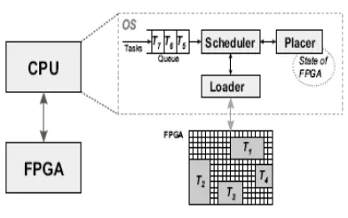
In Conventional algorithms the FPGA surface is modelled as a two dimensional array with X number of columns and Y number of rows called area matrix. Each cell in the array represents a CLB in the FPGA. Each empty cell is represented by 0 and every occupied cell is represented by 1. A typical system model is shown in Figure 1. The system assumes that the tasks arrive online, queued and placed in arrival order. As long as free area is available in the FPGA the incoming task will be placed on an unoccupied area on the FPGA. If there is no free space and the task cannot be delayed then
[image:2.595.311.507.154.277.2]the task is rejected. A good placement algorithm should reduce rejection rate.
Figure 1. System model
The tasks are non pre-emptive. Once a task is loaded onto the FPGA, it runs to termination. The tasks should be independent without any precedence constraints. These task parameters are defined as: for a task ti=( hi, wi, ai, si, di, xi, yi), hi
and wi represent its height and width respectively
and are measured in number of cells, ai, si and di
are the task arrival time, execution time and deadline time. The rectangular area assigned to the task by its top left corner (xi, yi) where xi: row
number and yi : column number. The size, arrival
time, execution time and deadline are uniformly distributed in a predefined region and a-priori unknown.
4. Z-ORDER SPACE FILLING CURVES
Z-curve has found applications in various problem domains leading to efficient algorithms for data classification and clustering. In two dimensions Z-order can be achieved by recursively partitioning the data into quadrants that is recursively dividing the cardinality of the array dimensions in half. The number of rows should be equal to number of columns. The generation of Z-order matrix of 8x8 is shown in Figure 2.
Figure 2.Generation Of Z-Order Matrix
5. PROPOSED TECHNIQUES
5.1 Z-order curve based placement
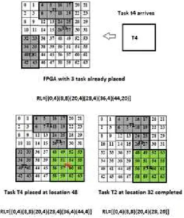
In this method the FPGA resources has been labeled in Z-order. A novel data structure called run length list has been introduced to describe the free space. The first value in each tuple indicates the starting location of the free area in Z-order while the second value indicates size of the free block. The Figure 3 illustrates the placement and removal of tasks on a 8 x 8 FPGA. The shaded region in grey indicates tasks already placed.
Initially when the FPGA is empty the free space run-length is FRL= {(0, 64)}.The run-length representation after each action is shown under each case. The online scheduler tries to find a placement and starting time for a newly arrived task such that it deadline is met. If it could not find a location the task will be put in waiting list and placement is attempted when any another task complete execution and is removed from FPGA. The task can wait until its laxity beyond which it cannot meet deadline and hence rejected. The
algorithm works in two modes: First fit and Best fit method.In First fit method the first confirmed feasible location will be used to place task. In best fit for each possible location fragmentation is calculated. The task is placed in a location that produces the least fragmentation. The fragmentation metric used in this algorithm is a one dimensional formula [11] as mentioned in equation 1, where fi indicates the vacant slots. This method
was chosen because all the empty slots fi are readily
available in our FRL representation.
F=1-∑fi2 /(∑fi)2 (1)
[image:3.595.311.498.342.564.2]The Figure 3 indicates the sequence for placing a task T4. In the example already discussed First fit select position 48 for placement while Best fit choose any one among 36 and 48 since both leads to same fragmentation.
Figure 3 Addition and removal of task on FPGA
The addition or deletion operation involves the updating FRL by inserting or removing entries to reflect the actual picture of vacant space. Block addition and deletion operations are shown in Figure 4.
5.2 Thermal aware model
Sub-cluster denoted by Pij are shown in figure 5
where i indicates the temporal group inside cluster j. The sub-clusters P11, P12, P13 and P14 consist of
tasks ending in the time interval [0, T]. Sub-clusters P21, P22, P23, P24 contain tasks with expire time
ending in interval [T ,2T] and so on. For time greater than 4T it will come back to sub-cluster group 1.The sub-cluster mentioned in each group will have the task ending in the same period and they will be physically separated by other time period zones which will be relatively empty. This is due to temporal property. This will keep the hotter regions to be separated by cooler regions thereby maintaining temperature at a moderate value. For a task that ends at a particular time we have four clusters to try. We try to select a location in a sub-cluster which satisfies our fitness function. The sub-clusters are sorted according to the fitness function. To calculate the fitness we consider a weighted function with the following parameters. Temperature, fragmentation and stress are the parameters used. The weights can be adjusted to give importance to any parameter we want or a combination of parameters. The temperature at a particular region where the block is placed is calculated using the following formula obtained from [13]
TJ=TA+ θJA*P (1)
where TJ is the junction temperature, TA is the
ambient temperature, θJA is the thermal resistance
of the package and P refers to total power consumed by the block. A suitable temperature spreading function is used is spread the heat generated. When the block is removed a cooling function is employed.
5.3 Performance metrics
Task rejection ratio is defined as ratio of number of tasks rejected to total number of tasks. Total waiting time is the sum of waiting time for the tasks till they get placed. Utilization ratio is given by ratio of volume of placed task to total volume of all tasks. Volume of task is found out by product of area with execution time. Penalty ratio is the ratio of volume of rejected task to the total volume of all tasks. When a task gets rejected, the total free area in reconfigurable device is called wasted area. Good placement algorithm will have more utilization, less penalty ratio, less temperature variations and less waste area and less rejection ratio.
6. EXPERIMENTAL RESULTS AND DISCUSSION
[image:4.595.309.512.402.699.2]We have measured the effectiveness of our placement strategy through a series of synthetic simulation. The two algorithms, developed in Matlab 7.8, have been simulated with FPGA of various sizes up to 64x64 basic blocks. (Z-curve requires the matrix to be square). Fifty data sets of 300 tasks each have been generated randomly from a user defined range as follows: Small task width and height [1-7], big tasks [8-16], execution time [1 to E], slack [1 to S], inter task arrival interval [0 to U]. The simulation of online placement on a 64x64 FPGA for temperature management is as shown in Figure 5. The white space in the figure shows the level of fragmentation in the FPGA. To evaluate the qualities of our approaches, we have made comparison with four different algorithms for task placement: a) Classical First fit algorithm with bottom left heuristics (BL) [12], b) Least interference fit (LIF) [12], c) 2D adjacency Technique (Deng) [9], d) Clook method is explained in Trong [10].
The Table 1 lists average temperature obtained by simulation of a 64x64 FPGA. Results show the rejection is slightly more for a temperature aware model because of the cluster based arrangement. But its temperature distribution is well balanced. The average number of hotspots generated is also listed. The best result is obtained for a case with temperature and fragmentation combined with equal weights in the fitness function. Compared to ordinary Z-order based placement the temperature has decreased by around 15 % as shown in table 1.
[image:5.595.80.272.276.501.2]Figure 5 Simulation of temperature aware Online Task Placement
Table 1. Simulation results for proposed temperature
aware method
algo Average
Rejection
Maximum
temperature
occured
No of
hotspots
generated
TBF(F) 0 82.50 13.55
TBF(T) 0.54 80.14 9.91
TBF(F+T) 0 79.82 8.72
ZBF 0 94.72 59.63
The experiment is also repeated with skewed probability distribution of task width and height to study the impact of task size on placement
quality. Figures [6-8] gives the performance of various methods for different workload.
Our placement method matches result with conventional method. The rejection rate was more for large sized task. The rejection rate also increases with decrease in inter-task arrival interval. When tasks arrive in quick succession then more number of tasks will be running on the FPGA leaving less room for the newly arrived task.
Figure 6 Reject ratio for task set with different workload
[image:5.595.86.510.375.749.2]Figure 8 Task rejection ratio for task sets having different execution time range
7. CONCLUSION
In this paper a new approach for online placement of task on a dynamic reconfigurable device labeled using Z-curve is being presented. We developed a run length based representation to define free space which helps us to find empty slots and estimate fragmentation quickly. Finally, the performance benefits of the new techniques have been measured through a series of synthetic simulations. A novel cluster based technique for temperature balancing on a FPGA is also proposed. Results show that overall temperature reduction is possible in a partial reconfigurable FPGA. Although we have considered only online task placement problem on FPGA, we believe that our method can be easily applied for other 2D bin packing problems of larger size.
REFERENCES
[1] Bazargan, K., Kastner, R., & Sarrafzadeh, M “Fast template placement for reconfigurable computing systems”. IEEE Design and Test -
Special Issue on Reconfigurable Computing,
January-March:2000, pp. 68–83.
[2] Walder, H., Steiger, C., & Platzner. M “Fast Online Task Placement on FPGAs: Free Space Partitioning and 2D-Hashing”. Proc. IPDPS-2003, RAW-2003, IEEE-CS Press,
2003, pp 178.
[3] Handa, M., & Vemuri, R “An efficient algorithm for finding empty space for online FPGA placement.” DAC, 2004, pp. 960–965. [4] Ahmadinia, A., Bobda, C., Bednara, M., &
Teich,J. “A New Approach for On-line Placement on Reconfigurable Devices”.Paper
presented at IPDPS,2004 pp. 134–140.
[5] Tabero, j., Septian, J., Mecha, H., & Mozos, D. “ Low fragmentation heuristics for task
placement in 2D RTR hardware
management”, Paper presented at 14th
International conference on field
programmable logic and application,2004 pp
241-250.
[6] Tomono,M., Nakanishi,M., Yamashita,S., Nakajima,N., & Watanabe,K “A new approach to online FPGA placement”. Paper
presented at 40th Annual Conference on
information Sciences and systems, 2006 pp
145-150.
[7] Jin Cui, Qingxu Deng, Xiu qiang He, Zonghua Gu, “An efficient algorithms for Online Management of 2D area of Partially Reconfigurable FPGAs.” paper presented at Design, Automation & Test in Europe
Conference, 2007.
[8] Thomas Marconi, Yi Liu, Koen Bertels, Georgi Gaydadjiev. “Intelligent Merging on-line task placement algorithm for partial Reconfigurable system.” Paper presented at Design, Automation & Test in Europe
Conference, 2008.
[9] Deng, Kong, Guan, Mingsong, Yi. “Online placement of real-time tasks on 2D partially run time reconfigurable FPGAs”. Fifth IEEE
International Symposium on Embedded
Computing, 2008.
[10] Trong-yen Lee, Che-cheng Hu & Chia-chun Tsai, “Adaptive free space management of on-line placement for Reconfigurable systems.” Proceedings of the IMECS, Vol .I,
2010
[11] Julius Gehr, Jorg Schneider, “Measuring
Fragmentation of Two-Dimensional
Resources Applied to Advance Reservation Grid Scheduling.” Proceedings of the 2009 9th IEEE/ACM International Symposium on
Cluster Computing and the Grid ,2009,pp
276-283
[12] Ahmadinia,A., Jurgen Teich, “Speeding up on-line placement for Xilinx FPGA by reducing Configuration Overhead.” Paper presented at International Conference VLSI-SOC 2003 on 1-3 Dec 2003,Germany, pp 118-122
[13] Sundararajan.P,Gayasen A,Vijaykrishnan N,
“Thermal characterization and Optimization
in platform FPGAs” Paper presented at