GRID-CONNECTED PHOTOVOLTAIC SYSTEM USING AN
ADVANCED BACKSTEPPING APPROACH
1
KHALDI NAOUFEL, 2 MALIKA ZAZI, 3 HASSAN MAHMOUDI 1,3
Mohammedia School of Engineer, Department of Electrical Engineering, Rabat, Morocco 2
Higher School of Technical, Department of Electrical Engineering, Rabat, Morocco
E-mail: 1 [email protected], 2 [email protected],3 [email protected]
ABSTRACT
The objective of this paper is to present a nonlinear approach to design a suitable controller system for the photovoltaic (PV) single-phase grid-connected system. The system structure includes a PV generator, Boost converter, and DC-AC inverter coupled to grid network. A backstepping controller is developed to extract maximum point power tracking (MPPT), to regulate the DC bus voltage, and to generate a sinusoidal current into the grid in phase with grid voltage in order to achieve unity power factor. The stability of the control algorithm is demonstrated by tools of Lyapunov analysis. Simulations show that the proposed controller system completely accomplishes listed aims even under atmospheric conditions variation. The performance of the proposed controller has been validated by numerical simulation in MATLAB SIMULINK.
Keywords: PV grid-connected system, backstepping technique, MPPT, power factor, Lyapunov stability
1. INTRODUCTION
Demand for electrical energy has remarkably increased during the recent years with growing population and industrial progress. Since long time ago, fossil fuels have served as the major source of generating electrical energy. However the transfer of energy resulting from photovoltaic con-version remains relatively feeble. Therefore, many tracking control strategies have been proposed in existing literatures, such as perturb and observe[1], incremental conductance[2], neural net-work[3], and fuzzy logic methods[4]. Referring to [5][8], PV energy application can be divided into two modes, that is the stand-alone PV system and the PV grid-connected system. In detail, the stand-alone PV system requires battery banks to store the energy. On the other hand, the PV grid-connected system is used in distributed generation systems to deliver the power to the utility grid. In order to get a high-quality power and eliminate the harmonics distortion of current and voltage, various control strategy is proposed to solve this problems in a passivity-based control[9], and hysteresis current control [6], power controlled [7]. This paper results show that the proposed backstepping control can track maximum power point (MPP) in different temperature and irradiation, and to maintain the grid current with the grid voltage by ensuring the tight regulation of the DC-bus. The control inputs are the
duty cycles of the boost converter and DC-AC inverter. The controller system in addition to achieve the mentioned objectives, it helps also to reduce the harmonic content of the network current and assure an excellent output characteristic of high accuracy and good robustness in front of system’s perturbation.
The sequential work flow of this paper is as follows: the next section, mathematical modelling of a grid connected PV system has been described. Section 3 presents a controller design of the converters using a backstepping method. Simulation works in Matlab/Simulink, and results are discussed in Section 4. Lastly, in section 5, a precise conclusion has been added to finalize the work.
2. PV GRID-CONNECTED SYSTEM
MODELLING
Figure 1: PV Single-Phase Grid-Connected System
2.1 PV Modelling
There are various methods to perform modeling work on the PV module, and the most of them is described by using mathematical modeling [2][3]. The equivalent circuit of a PV array can be depicted in Figure 2 where is current source of PV array, is an equivalent shunt resistance, is an equivalent series resistance, and are the output current and output voltage of PV array, respectively. In general, for simplicity and are assumed to be open circuit and short circuit, respectively. The simplified mathematical model of the output current is given as [2]:
Figure 2: The Equivalent Circuit Of A PV Array
Where q is the electron charge, k the Boltzmann’s constant , p is the p–n junction ideality factor, T is the cell temperature, is the cell reverse saturation current, is the number of solar cells connected in series, and is the number of solar cells connected in parallel. In addition, the mathematical model of the reverse saturation current is given below:
With
Where is the cell reference temperature, is the reverse saturation current at is the band-gap energy of the semiconductor
and is a thermal potential at .
The current source of PV array , varied according to solar irradiation and cell temperature, is given below:
Where is short-circuit current at reference temperature and radiation, E is the solar irradiance and K, the temperature coefficient for short-circuit current. Using the equations 1 to 4 the PV panel can be modelled.
The table below represents the parameters of the PV module,is made by Shell solar company andproduct name is SP75.
TABLE 1:PARAMETERS OF SHELL SP75
Parameters Values
Open Circuit Voltage(Voc) 21.7Volt Short Circuit Current(Isc) 4.8Amp Voltage at Pmax(Vmpp) 17Volt Current at Pmax(Impp) 4.41Amp Maximum Power (Pmpp) 75Watt Number of Cell 36
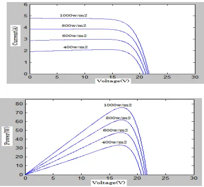
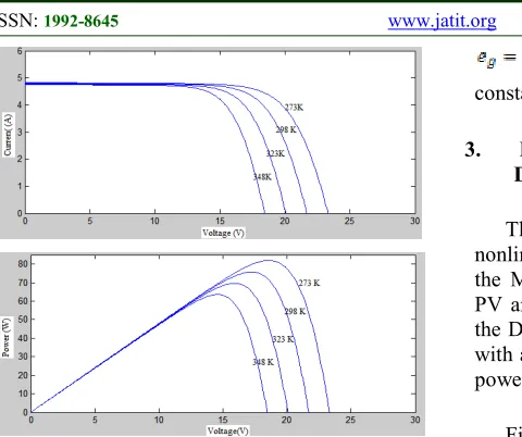
The associated power-voltage and current-voltage characteristics curve under changing atmospheric conditions (irradiation and temperature) are shown in Figs. 3 and 4.
[image:2.612.330.505.355.437.2] [image:2.612.314.513.504.686.2]Fig. 4 I-V And P-V Characteristics Of Solar Module For Different Temperature
2.2 Single-phase Grid-connected PV System Modelling
As can be seen in Figure 1, the boost converter consists of the switch K1 controlled by a switching signal (i.e., OFF or ON respectively) and the DC-AC inverter consists of four switches K21, K22, K23, K24 controlled by a switching signal
.
The switching signal and can also be generated via a pulse-width modulation (PWM) scheme with an input signal andoutputted by the controller. The development of the model switched system is based on the application of Kirchhoff's laws. Thus, we obtain:
Where and are
respectively, the average values over switching period of the PV voltage, PV current, boost inductor current, DC bus voltage, grid voltage, and grid current. is the input capacitor, L is the inductor of the boost converter and R is the equivalent series resistance of the inductor. is the DC link capacitor, is the filter inductor and is the equivalent series resistance of the filter inductor. The control inputs and are duty cycles of the switching signals and .The grid voltage
with a constant amplitude A and a constant frequency
.
3. BACKSTEPPING CONTROLLER
DESIGN
[image:3.612.95.335.72.273.2]The aim of this section is developing a nonlinear controller that will be able to: (i) achieve the MPPT even with variations of irradiation and PV array temperature, (ii) ensure the regulation of the DC bus voltage, (iii) inject a sinusoidal current with a good quality in the network, which proves a power factor close to unity.
[image:3.612.318.520.352.465.2]Figure 5 depict the structure of whole controlled system. The MPPT controller and power factor correction (PFC) controller will be synthesized using backstepping approach [10][11], and the DC voltage will be regulated by a simple proportional-integral corrector.
Figure 5: Control scheme of the whole system
3.1 MPPT Controller
The key goal of the MPPT Controller module is to extract maximum available power from PV array for any specific environmental variation. This is done with the help of an appropriate duty cycle signal used to regulate the controlled output
of photovoltaic array to its reference
in order to drive boost converter to achieve the MPP.
Design step 1
Let us introduce the following tracking error:
Using 5 and 6 , time derivation of , we obtained the following error dynamics:
(7) Treating the boost inductor current as a virtual control input, with respect to candidate Lyapunov function indeed, its time derivative is given by:
(8) In the above equation, if we chose as a virtual control variable, where is the desired value of the boost inductor current, we can find the following stabilizing function of
:
(9) Where is a positive design parameter. The desired value called stabilization function, is given by :
(10) Design step 2
As is not the actual control input, a new error variable
,
between the virtual control and its desired value should be vanish, then according to 5 and 7, we obtain :(12)
and adding 10, we defind and
:
Time derivative of the stabilising function is the following:
(15)
Consider the augmented candidate Lyapunov function:
Time derivative of is given as follows:
(17) The control law which guarantees the global stability with respect to candidate Lyapunov function as follows :
(18)
Where being a design parameterthe dynamics of Lyapunov function is reduced to:
this vector error ensures that the converges asymptotically to the origin. Therefore, the MPPT is achieved.
3.2 PFC Controller
As can be seen in Figure 3, to attain the unity power factor, it is necessary to regulate the DC link voltage to its desired value via an outer voltage control loop. Moreover, there is an inner control loop in cascade which generates an output current in phase with the grid voltage and ensures a low current harmonics. The grid current should reach a reference signal through the inner control loop:
is a tuning parameter adjusted by the following PI control law:
(21) Where and are respectively the proportional and integral gain.
(22)
Consider the candidate Lyapunov
function , and its derivative with respect to time is given by :
(23) We deduce then the following stabilizing control law:
(24)
4. SIMULATON RESULTS
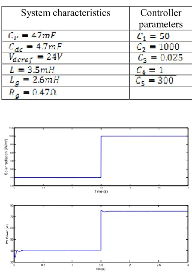
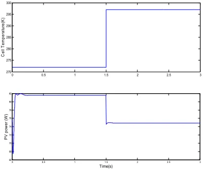
In order to investigate the performance of the proposed backstepping control algorithm, a numerical simulation was made in the environment Matlab/Simulink. The system characteristics and controller parameters are summarized in table 2. Two cases were selected to demonstrate the design results. In the first one, the solar radiation changes its value as follows: 500W/ ²to 1000W/ ²at = 1.5 while the temperature is kept constant at 298K. In the second case, the temperature has variable values as follows: 273K to 298K at = 1.5 while the solar radiation is kept constant at 1000W/ ².Figures 6 to 13 gives the simulation results when the reference of the DC bus voltage
is = 24 .
Figures 6 and 10, show that the backstepping method deliver the suitable duty cycle signal used to drive boost converter to reach the MPP very quickly and with an excellent performances and high accuracy even with variations of atmospheric conditions.
Figures 7 and 11 illustrate respectively, the PV array voltage, the PV array current, the boost inductor current and the DC bus voltage, we note that a good concordance between theoretical values and thus output signal obtained by Matlab. It is noted also that the Dc link voltage is regulated to the set value with a good efficiency.
Figures 8 and 12, show that the current and the grid voltage are in phase, and sinusoidal. As a result, the designed PV grid-connected system reaches unity power factor. They indicate also that the injected current to grid tracks the reference value .
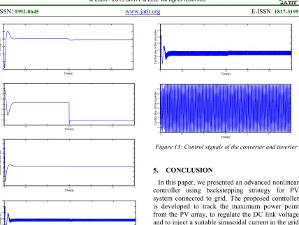
Finally in Figures 9 and 13, are presented the control signals and , it is clear that they are bounded.
Unfortunately, this method presents a limitation in terms of overall cost, as comparing with other techniques. Analog implementation is generally cheaper and less complex than its digital counterpart, which normally requires hardware like a number of sensors, software and programming.
TABLE 2:PARAMETERS OF THE WHOLE SYSTEM
System characteristics Controller parameters
0 0.5 1 1.5 2 2.5 3
400 500 600 700 800 900 1000 1100
Time (s)
S
o
la
r
ra
d
ia
ti
o
n
(
W
/m
²)
0 0.5 1 1.5 2 2.5 3
30 40 50 60 70 80
time(s)
P
V
P
o
w
e
r
(W
)
[image:5.612.321.512.237.510.2]0 0.5 1 1.5 2 2.5 3
13 14 15 16 17 18 19 Time(s) P V V o lt a g e ( V )
0 0.5 1 1.5 2 2.5 3
2 2.5 3 3.5 4 4.5 Time(s) P V c u rr e n t (A )
0 0.5 1 1.5 2 2.5 3
-5 0 5 10 15 20 Time(s) In d u c to r c u rr e n t (A )
0 0.5 1 1.5 2 2.5 3
[image:6.612.93.519.63.597.2]0 5 10 15 20 25 30 35 40 Time(s) D C l in k v o lt a g e ( V ) vdc vdcref
Figure 7: PV voltage, PV current, inductor current, DC link voltage
0 0.5 1 1.5 2 2.5 3
-12 -10 -8 -6 -4 -2 0 2 4 6 8 Time(s) ig ( A ) a n d i g re f (A ) grid current reference grid current
0.5 0.55 0.6 0.65 0.7 0.75
-15 -10 -5 0 5 10 15 20 Time(s) ig ( A ) a n d e g ( V )
[image:6.612.303.519.71.273.2]Grid current ig Grid voltage eg
Figure 8: PFC cheeking and grid current with its reference
0 0.5 1 1.5 2 2.5 3
0 0.1 0.2 0.3 0.4 0.5 0.6 0.7 Time(s) C o n tr o l la w o f th e c o n v e rt e r
0 0.5 1 1.5 2 2.5 3
0 0.1 0.2 0.3 0.4 0.5 0.6 0.7 0.8 0.9 1 Time(s) C o n t ro l la w o f th e i n v e rt e r
Figure 9: Control signals of the converter and inverter
0 0.5 1 1.5 2 2.5 3
270 275 280 285 290 295 300 C e ll T e m p e ra tu re (K )
0 0.5 1 1.5 2 2.5 3
[image:6.612.325.523.311.476.2]66 68 70 72 74 76 78 80 82 Time(s) P V p o w e r (W )
[image:6.612.96.298.460.614.2]0 0.5 1 1.5 2 2.5 3
14 15 16 17 18 19 20 Time(s) P V v o lt a g e ( V )
0 0.5 1 1.5 2 2.5 3
4.1 4.2 4.3 4.4 4.5 4.6 4.7 4.8 4.9 Time(s) P V c u rr e n t (A )
0 0.5 1 1.5 2 2.5 3
-4 -2 0 2 4 6 8 10 12 14 16 Time(s) In d u c to r c u rr e n t (A )
0 0.5 1 1.5 2 2.5 3
[image:7.612.94.522.65.388.2]0 5 10 15 20 25 30 35 40 Time(s) D c l in k t v o lt a g e ( V ) vdc vdcref
Figure 11: PV voltage, PV current, inductor current, DC link voltage
0 0.5 1 1.5 2 2.5 3
-15 -10 -5 0 5 10 Time(s) ig ( A ) a n d i g re f (A ) grid current reference grid current
0.7 0.75 0.8 0.85 0.9 0.95 1 1.05 1.1 1.15 1.2 -15 -10 -5 0 5 10 15 Time(s) ig ( A ) a n d e g ( V )
Grid current ig Grid voltage eg
Figure 12: PFC cheeking and grid cur-rent with its reference
0 0.5 1 1.5 2 2.5 3
0 0.1 0.2 0.3 0.4 0.5 0.6 0.7 Time(s) C o n tr o l la w o f th e c o n v e rt e r
0 0.5 1 1.5 2 2.5 3
0 0.1 0.2 0.3 0.4 0.5 0.6 0.7 0.8 0.9 1 Time(s) C o n tr o l la w o f th e i n v e rt e r
Figure 13: Control signals of the converter and inverter
5. CONCLUSION
In this paper, we presented an advanced nonlinear controller using backstepping strategy for PV system connected to grid. The proposed controller is developed to track the maximum power point from the PV array, to regulate the DC link voltage and to inject a suitable sinusoidal current in the grid with a unity power factor. The synthesis of the regulator was achieved by ensuring an asymptotic stability in the sense of Lyapunov. Simulation results under Matlab/Simulink prove that the controller guarantees a satisfactory performance and high efficiency even with a variation of irradiation and temperature.
REFRENCES:
[1] M.A.A. Mohd Zainuri, M.A. Mohd Radzi, Azura Che Soh and N. Abdul Rahim, “Comparative Analysis of the Perturb-and-Observe and Incremental Conductance MPPT Methods”, The 8th International Symposium On Advanced Topics In Elec-trical Engineering, 2013. [2] Tekeshwar Prasad Sahu, T. v. Dixit, “Modelling and Analysis of Perturb and Observe and
Incremental Conductance MPPT Algorithm for PV Array Using Cuk Converter”, IEEE Student’s Conference on Electrical, Electronics and Computer Science, 2014, pp. 1–6.
[3] Naoufel Khaldi, Hassan Mahmoudi, Malika Zazi, Youssef Barradi, “Implementation of a MPPT Neural Controller for Photovoltaic Systems on FPGA Circuit”, WSEAS Transactions on power systems. Vol. 9, 2014, pp. 471–478.
[image:7.612.91.318.73.432.2]fuzzy logic MPPT control and modified H-bridge inverter in photovoltaic system”,
International Conference on Electronics and Communication Systems (ICECS), 2014, pp. 1– 6.
[5] H. Radwan, M. Orabi, “The non-ideality effect of optimizing the PO MPPT algorithm for PV Stand-alone applications”, IEEE the 34th
International Conference on
Telecommunications Energy (INTELEC), 2012, pp. 1–7.
[6] F. Zare, G.Ledwich, “A hysteresis current control for single-phase multilevel voltage source inverters: PLD implementation”, IEEE Transactions on Power Electronics.Vol.17, 2002, pp. 731–738.
[7] Huijuan Li, Yan Xu, S.Adhikari, D.T. Rizy,Fangxing Li, P. Irminger, “Real and Reactive Power Control of a Three-Phase Single stage PV System and PV Voltage Stability”, IEEE Power and Energy Society GeneralMeeting. 2012, pp. 1–8.
[8] Jui-Liang Yang, Ding-Tsair Su, Ying-Shing Shiao, “Research on MPPT and Single stage Grid-Connected for Photovoltaic System”, WSEAS Trasactions On Systems.Vol.7, 2008, pp.
1117–1131.
[9] G. Perez-Ladron, V. Cardenas, N. Visairo, F. Pazos, “Passivity-based control technique for UPS inverters” European Control Conference (ECC), 2007, pp. 5734–5739.
[10] M.L. McIntyre, M. Schoen, ; J. Latham, “Back-stepping control of a capacitance-less photo-voltaic power converter with maximum power point tracking” , IEEE 39th Photovoltaic Special-ists Conference (PVSC), 2013, pp. 2908–2913.
[11] M. Honsberg, T. Radke, “3-level IGBT modules with trench gate IGBT and their thermal anal-ysis in UPS, PFC and PV operation modes” , 13th European Conference on Electronics Power andApplications, (EPE), 2009, pp. 1–7.