VAX cluster Systems
Digital Technical Journal
Digital Equipment Corporation
Cover Design
VAX cluster systems are featured in this issue. The central connection between the elements in a cluster is called the Star Coupler. Our star-filled cover evokes the thousands of
VAXcluster systems now operating worldwide. The image was created using the Lightspeed System.
The cover was designed by Barbara Grzeslo and Tim Roberts of the Graphic Design Department.
Editorial Staff
Ediwr- Richard W. Beane Production Staff
Production Editor- Jane C. 131ake Designer- Charlotte Bell
Interactive Page Makeup- Terry Reed Advisory Board
Samuel H. Fuller, Chairman Robert M. Glorioso John W. McCredie Mahendra R. Patel F. Grant Saviers William D. Strecker
The Digital Technical journal is published by Digital Equipment Corporation, 77 Reed Road, Hudson, MassachusettS 01749.
Changes of address should be sent to Digital Equipment Corporation, attention: Media Response Manager, 444 Whitney Street, NR02-1/J5, Northboro, M.A 01532-2599
Comments on the content of any paper are welcomed. Write to the editor at Mail Stop HL02-3/K11 at the published-by address. Comments can also be sent on the ENET to RDVAX::BEANE or on the ARPANET to BEANE%RDVAX.DEC@DECWRL.
Copyright© 1987 Digital Equipment Corporation. Copying without fee is permiued provided that such copies are made for use in educational institutions by facuhy members and are not distributed for
commercial advantage. Abstracting with credit of Digital Equipment Corporation's authorship is permitted Requests for other copies for a fee may be made to the Digital Press of Digital Equipment Corporation. All rights reserved.
The information in this journal is subject to change without notice and should not be construed as a commitment by Digital Equipment Corporation. Digital Equipment Corporation assumes no responsibility for any errors that may appear in this document.
ISBN 1-55558-004-1
Documentation Number EY-8258E-DP
The following are trademarks of Digital Equipment Corporation: CI, DEC, DECnet, DECnet-VAX, DECsystem-1 0, DECSYSTEM-20, Digital Network Architecture (DNA), Digital Storage Architecture (DSA), the Digital logo, HSC, Local Area VAXcluster, MicroVAX, MicroVAX II, MicroVAX 2000, Q-bus, RJ\1S- I I , SA482, UNIBUS, VAX, VAX-11/750, VAX-11/780, VAX-11/782, VAX-11/785, VAX 8600, VAX 8650, VAX 8700, VAX 8974, VAX 8978, VAXcluster, VAXstation, VAXstation JJ, VAXstation ll/GPX, VA.Xstation 2000, VMS, VT, VT220
IBM is a registered trademark of International Business Machines, Inc.
Intel is a trademark of Intel Corporation.
Lightspeed is a trademark of Lightspeed Computers, Inc.
Contents
V AXcluster Systems
7 The VAX cluster Concept: An Overview of a Distributed System Nancy P. Kronenberg, Henry M. Levy, William D. Strecker, and Richard J. Merewood
22 The System Communication Architecture Darrell J. Duffy
29 The VAX/VMS Distributed Lock Manager
William E. Snaman, Jr. and David W. Thiel
4 5 The Design and Implementation of a Distributed File System Andrew C. Goldstein
56 Local Area VAXcluster Systems Michael S. Fox and John A. Ywoskus
69 VAXcluster Availability Modeling
Edward E. Balkovich, Prashant Bhabhalia, William R. Dunnington, and Thomas F. Weyant
80 System Level Performance of VAX 8974 and 8978 Systems Daeil Park, Rekha D. Von Ehren, Tzyh-jong Wang, and Nii N. Quaynor
Editor:ls Introduction
Richal"d W. Beane Editor
VAXc luster systems are closely cou pled configu· rations of VAX CPUs and storage devices . The VAX C PU a t a n y n o d e c a n c o m m u n i c a t e w i t h the processor and storage dev ices at a n y other node in the cluster . The i nterconnects and soft· ware used to activate this unique concept allow data transfers at u p to 70 megabits per second between nodes. This issue of the Digital Techni· cal journal conta i ns papers about some of the key hardware and software features i n these sys· terns , as wel l as some measures of their perfor· mance . Since several orga n i zations within Digital are responsible for various VAXcluster features , these papers are comribured by engineers from a wide spectrum of engineering groups.
S in c e the VAXc luster concept spans s u c h a r a n ge of t e c h n o l o g i e s , t h e f i rst p a p e r i s a n overview ex p l a i ni n g genera l ly how t hese sys tems work. Nancy Kronenberg, Han k Levy, B i l l Strecke r , and Richard Merewood describe t h e architecture, the storage control , t he VMS soft· ware a lterations, and the mu l ti tude of activi ties that control access to the storage devices.
The System Commu n i c a t i o n Arc h i tecture , described by Darre ll Duffy, is the structure that a l l ows the nodes in a VAXcluster system to coop erate. This relatively si m p l e framework governs t he s h a r i n g of data betwe e n resou rces at t h e nodes a n d binds together applications that run on d i fferent VAX CPUs.
2
Add i t ional features were needed i n the VMS software to accommodate ac cess i n g d i s ks on multiple systems. The distribu ted lock manager, described by Sandy Snaman and Dave Thie l , pro· vides the synchron ization needed to accomplish transparent data transfers between c l uster mem· hers. Other changes were a lso needed to broaden the file functions performed by the VMS software . Andy Goldstei n relates some alternative ways to expand those functions and how the QJO proces· sor was extended ro sync hroni ze fi l e accesses. The resul ting system of locks and queues pro· v ides a con s i stent sequence for managi n g d is tributed fi les.
The next paper. by M i ke Fox and joh n Ywoskus, descri bes the extension of the VA.-'Ccl uster con cept ro systems connected w i t h a n E t herne t . Tbcsc Local Area VAXcluster systems use speci a l software t o provide fu nctions needed b y clusters, but not p rov ided by E t hernet software . Thus, M icroVAX II and other sma l l VAX systems can be clustered to yield sign i ficant a mounts of process· ing power.
The last t hree papers deal with performance aspects of VAXcluster systems. The paper by Ed Ba l kovich, Prashant Bhabhalia, D ick Dunnington, and Tom Weyant d iscusses the results of a VAX· cluster model that demonstrates how redundancy im proves ava i l ab i l i ty. The n , Dale Pa r k , Re kha Von Ehren, T·J. Wang, and Nii Quaynor describe two mode ls they developed to measure the per· formances of VAX 8974 and 8978 systems. These models, based on ben c hmarks ru n in d i fferent environments, use a VAX 8700 CPU for a base l i ne comparison .
Biographies
Edward E. Balkovich Ed Ba lkov ich is the manager of V�'{c luster System Engi neering, which addresses issues of VAXcluster pcrformance, availabi l i ty and architecture for H igh Performance Systems. He was Digita l 's associate director of Project Athena at M . I .T. and is an Adjunct A.o;sociate Professor at Brandeis University. Before joining Digital in 19R I, Eel was a faculty member at the University of Connecticut. He earned his B.A. degree ( 1968) from the University of Cali fornia at Berkeley, and his M . S. ( 197 1) and P h . D. ( 1976) degrees from the University of Californi a at Santa Ba rbara . He is a member of t he ACM and IEEE.
Prashant Bhabhalia A principal engi neer i n V�'Ccl uster Systems Eng i· neering, Prashant Bhabhalia develops and in terprets re liabi l i ty and avai labi l· ity mode ls. Earl ier, he was a program manager in Computer Systems Manu facturing and a sen ior engineer in GlA Manufacturing. Before joi n i ng Digital in 19RO, Prashant was an industrial engi neer at Norton Company and Gits Plastic Corporation . He holds an M.S. I .E. degree ( 1974) from the Polytech nic I nstitute of Brooklyn and a B . S . M.E . degree ( 197 2) from the M.S. Univer sity in India . Prashant is a senior member of l . I .E.
Xi-Ren Cao A.<> a principal software engineer in the H igh Performance Sys tems and Clusters Group, X i - Ren Cao mode ls and evaluates VAXcluster con figurations. Before joining Digital i n 1986, he was a research fe llow at Har vard Universiry. Xi -Ren has published over 20 technical papers on performance evaluation, si mulation, srochastic systems, queuing networks, and control t heory, and has co-authored a book "Perrurbation Analysis of Dis crete Event Systems ," to be published in 1988. He received h is P h . D . degree from Harvard Un iversity i n 19R4 and is a member of IEEE.
Fernando C. Colon Osorio Fernando Colon Osorio graduated from the Un iversity of Puerto Rico ( B .S . E . E . , 1970) and the University of Massachu setts ( M . S . , Ph . D , 1976). Joining Digital i n l97(J. he helped design the PDP-1Ij60 and PDP-11/74 systems and managed the LAN group i n Corporate Research . Fernando also managed the overall design verification for the V�'{ 8600 project . In H igh Performance Systems. he now manages the systems research and advanced development group, responsible for VAXclusters. fault tolerance, advanced arc h itectures, and performance ana lyses. He was Associate Ed i tor of the IEEE Transactions on Com puters and is the co-author of "Engineering I n te l l igent Systems."
Darrellj. Duffy As a consulting software engi neer. Dan-ell Duffy works on the network architecture for VAXcluster systems . On prev ious projects , he led the deve lopment of operating systems for parallel processors and wrote software for the Local Area Terminal protocol . Darre l l helped to deve lop DECnet software after joi n i ng Digital in 1977 He received a B . S . in com puter science from West Virginia University in 197 2 and worked at the Un i versity of Florida . Darre l l and three other Digital engi neers have applied for a parent on the LAT protocol .
Biographies
4
William R. Dunnington Dick Dunni ngton is a principal qual i ty engineer working on availabil i ty modeli ng in the Com puter System Manufactu ring Grou p . Prev iously, he was a quali ty engi neer in the Far East Manufactu ring Grou p , working on personal computer memories . Before join ing Digital i n 1979, D ick was a captain i n the U .S . Army. H e received a n A<>sociates degree in liberal arts from S.U . NY ( 1973) and a B.S. degree in engineering science from the University of Nebraska ( 1 97 4). Dick, a member of SIAM and ASQC, is a l so a Certified Qua l i ty Engineer.
Michael S. Fox I n J 977, M i ke Fox joined Digital after earning his M . S . ( 1977) and B.S. ( 1976) degrees i n computer science from Rensselaer Polytechnic Institute. Initial ly, he helped to develop the RSXI 1 M-PLUS soft ware, then served as archi tect and supervisor on the PRO/SERVER project . I n D i gi tal's Graduate Engineering Education Program , M i ke returned to Rensse l aer for a year as a faculty member in computer science. Back at Digita l , he joined the VMS Engineering Group and lead the p roject that developed the Local Area VAXcluster software. M i ke is now a consulting software engineer.
Andrew C. Goldstein Andy Goldstein received h is B . S . E . E . and M . S . E . E . degrees from M. l .T in 197 1, and joined Digital in 1973. H e was ini tially responsible for the fi le system in the RSX-11 D and RSX-11 M systems, and became a charter member of the VMS Deve lopment group. Andy designed and implemented the VMS fi le system, and worked as wel l on the VMS ljO and executive software . More recently, he designed the security features i n VMS version 4 . 0 and helped w i t h the VAX c l uster file system . Andy i s now a sen ior consu ltant software engineer, and is a member of Tau Beta Pi , Eta Kappa Nu , Sigma Xi , and ACM .
Nancy P. Kronenberg Nancy Kronenberg i s a sen ior consu ltant software engineer in the Advanced VAX Deve lopment Grou p . She is currently project leader of the microcode team for a new VAX CPU. Previously, Nancy worked i n the VMS Development Group where she assisted with the SCA specifica t ion and wrote the CI port driver and pan of the VMS SCA services. Before joi n i ng Digita l i n 1978, she was a systems analyst at Massachusetts Computer Associates and at Appl ied Data Researc h . Nancy earned her AB degree i n physics from Corne l l Un iversity in 196 7 .
Richard J. Merewood
Richard Merewood is the software development
manager for the DECnet-VAX , Local Area VAXcluster, and VAXcluster soft·
ware projects. In Reading, England, he managed the development of Digital's
X . 25 networking products, performed advance development on the ISDN
project, and supervised a modem development project. Before joining Digi
tal in 1 980, Richard was an international consultant in data communications
and transaction processing. He studied electrical engineering at the I mperial
Col lege of Science
&
Technology, London .
Daeil Park
As a principal software engineer in the Systems Performance
Group, Dale Park executes and ana lyses tests to determine VAXcluster per·
formance. He is particularly involved with measuring the performance of
application programs on these systems. Dale joined Digital in 1 983 after
receiving his M.S. degree in computer engineering ( 1 983) from Case West
ern Reserve University. Earlier, he was a system design engineer at Samsung
Electronics Co . Ltd , in Korea . Dale earned his B.S. degree in electrical engi
neering (1977) from Seoul National University in Korea .
Nii N. Quaynor
After earning his B . E . degree from Dartmouth Col lege i n
1973 and his Ph . D . from S . U . N . Y . at Stony Brook in 1 97 7 , Nii Quaynor joined
Digital in 1 978. He first worked in corporate research on multimicro sys
tems. In 1 98 2 , Nii joined the VAX 8600 project as a consu lting software
engineer and created models for large-scale CAD applications using a register
transfer language . Later, he worked on the verification of the VAX 8600
design . Nii is now the manager of the System Performance Group in High Per
formance Systems.
William E. Snaman, Jr.
Sandy Snaman is a principal software engineer in
the VMS Development Group, currently working on software for VAXcluster
systems and the distributed lock manager. Sandy has also developed and
taught VAXcluster courses in Educational Services and was a software main
tainab i l ity engineer for Customer Services Systems Engineering. He joined
Digital in 1 980 after eight years in the U.S. Navy. Sandy holds a B.S. degree
( 1 985, Magna Cum Laude) from the University of Lowe l l , where he is now
completing his M.S. degree in computer science.
William D. Strecker
Bill Strecker, vice president for Product Strategy and
Architecture, joined Digital after receiving h is B.S. , M . S . , and Ph . D . degrees
from Carnegie-Mellon University. Bil l's work on cache memories led to the
PDP- 1 1 /7 0 system , and he also led the team that developed the VAX archi
tecture . Bill guided Digital's interconnect strategy, which lead to the com
puter interconnect (CI) and the Systems Communication Architecture . He
holds several patents on CPU designs and computer interconnects. Bill and
was elected to the National Academy of Engineering in 1 986.
Biographies
6
David W. Thiel
Dave Thie l , a consulting software engineer, is currently
studying future directions for VAXcluster systems in the VMS Development
Group . He was project leader for the i nitial VAXcluster support i n VMS ver
sion 4 . 0 . Dave a lso worked on the executive and data compression areas of
the VMS software. Dave joined Digital i n 1 980 from GenRad, I nc . , where he
was a principal software engineer. He earned his B . S . E . E . , M . S. E . E . , and Elec
trical Engineer degrees from M . I .T. in 1 97 2 . He is a member of Tau Beta Pi ,
Eta Kappa Nu, ACM , a nd IEEE .
Rekha D. Von Ehren
As
a senior software engi neer i n the Systems Perfor
mance Group , Rekha Von Ehren works on performance measurements and
ana lyses for VAXcl uster systems. Previously, she analyzed the performance of
VAX 8600 and 86'50 CPUs. Rekha joi ned Digital in 1 983 after receiving her
M . S . degree in i ndustrial engineering from the University of Wisconsin . She
also earned an M . S . degree ( 1 98 1 ) i n operations research from the London
School of Economics and a B . S . degree i n statistics and computing from North
London Polytechnic. Rekha has just given birth to her first chi ld, a baby boy,
named Samuel.
Tzyh-Jong Wang
As
a pri ncipal engineer i n the Systems Performance
Group, Tzyh-Jong Wang conducts modeling stud ies to measure system per
formance . He analyzes VAXcluster configurations, on- l i ne transaction pro
cessing, and other advanced systems. Before joining Digital in 1 98 7 , Tzyh
jong was a lecturer at the University of Wisconsin at Madison, where he
received h is M . S . and P h . D . degress ( 1 98 7 ) in information systems. He a lso
earned a B.S. I . E . degree ( 1 978) from the Nationa l Tsi ng-Hua University, Tai
wan . Tzyh-jong is a member o f ACM , I E E E , ORSA, a nd TIMS.
Thomas F. Weyant
Tom Weyan t is the manager of the Systems Rel iabi l i ty
Engineering Group i n Computer Systems Manufacturi ng.
As
a consulting
engineer, he worked on systems reliab i l i ty a nd avai labi l i ty modeling, com
puter- i nterconnect reliab i l i ty, infant-morta.lity and long-term failure-rate
model ing, and was the manager of advanced development . Before joining
Digital i n 1 98 5 , Tom worked for ten years at AT&T Bel l Laboratories and
Hughes Aircraft Company. He earned his 13.S. M . E . degree ( 1 9 7'5) from the
University of Ca liforn ia at Santa Barbara , and his M .S. and Ph . D . degrees
( 1 98 1 ) i n operations research from UCLA.
Nancy P. Kronenberg
Henry M. Levy
William D. Strecker
Richard J. Merewood
The VAXcluster Concept:
An Overview of a Distributed System
A VAXcluster system is a highly available and extensible configuration of VAX computers that operate as a single system. To achieve high perfor mance in a multicomputer environment, a new communications architec ture, communications hardware, and distributed software had to be jointly designed. The software is the VAXjVMS operating system, using a distributed lock manager to synchronize access to shared resources. The communications hardware includes a 70-megabit per second message-ori ented interconnect, and an interconnect port that performs communica tions tasks traditionally handled IJy software. The Local Area VAXcluster system, an implementation of the VAXcluster architecture, uses a standard Ethernet as its interconnect. This development provides VAXcluster func tions for the Micro VAX family.
Contemporary mul ticomputer systems typically
lie at the ends of the spectrum delimi ted by
tightly coupled multiprocessors and loosely cou
pled distributed systems. H istorically, loosely
coupled systems have been characterized by the
physical separation of processors, low-bandwidth
message-oriented interprocessor communication ,
and independen t operating systems . 1·2··H Con
versely, tightly coupled systems have been char
acterized by close physical proxi mity of proces
sors, high-bandwidth communication through
shared memory, and a single copy of t he operat
ing system .'·6·7
An
intermediate approach taken at Digital
Equipment Corporation was ro build a "c losely
coupled" structure of standard VAX computers,R
caJ i ed a VAXcluster syste m . By closely coupled ,
we imply that a VAXcluster system has character
istics of both loosely and tightly coupled systems .
On one hand, a VAXcl uster system has separate
processors and memories connected by a mes
sage-oriented i nterconnect, running i nstances of
the same copy of the distributed VAXfVMS oper
ating system . On the other hand , the initial
The original version o f 1his paper appeared in "VAXclus1ers: A Closely·Coupled Dis1ribU1ed Sys1em," by Nancy P. Kronen berg, Henry M. Levy, and William D. S1recker, published in ACM Transactions on Computer .\:ystems, Vol. 4, No. 2,
May 1986 Copyrigh1 1987, Associa1ion for Compming Machinery, Inc.
Digital Tecbtzical Journal
No. 5 September 1987
implementation of the cluster rel ied on close
physical proximity, a single (physical and logi
cal) security domain, shared physical access to
d isk srorage , and high-speed memory-to-memory
block transfers between nodes .
The goals of the VAXcluster multicomputer sys
tem are high availability (in suitable configura
tions) and easy extensibility to a large number of
processors and device controllers. In contrast to
other h ighly available systems,9 10 1 1 · 1 2 a VAXclus
ter system is built from general-purpose, off-t he
shelf processors ranging in size from MicroVAX
workstationsl.\ to high-performance VAX CPUs,
and a general-purpose operating system .
A key concern i n this approach is system
performance . Two important factors in the per
formance of a multicomputer system are the
software overhead of the communications archi
tecture and the bandwidth of the computer inter
connect . To address these issues, severa l develop
ments were undertaken as part of the original
VAXcJuster design , i ncl uding
•
A simple, low-overhead communications
architecture whose functions are tai lored to
the needs of highly available, extensible sys
tems. This architecture is called the System
Communication Arch i tecture (SCA).
•
A
very high speed message-oriented Computer
I nterconnect, cal led the CI bus
lbe V AXcluster Concept: A n Overview of a Distributed System
• An
intelligent hardware interface to the CI
bus, called the C I port, that implements part
of the SCA in hardware
• An
intelligent, message-oriented mass storage
controller that uses both the CI bus and the Cl
port i nterface
This combined software and hardware archi
tecture supports a high-performance communi
cations structure for interconnecting high-perfor
mance VAX systems. For low-end VAX CPUs, the
Local Area VAXcluster system has been developed
to perm it workstations interconnected by means
of the Ethernet to share a common file system,
printers, and batch processing. Workstation users
can derive the benefits of centra lized timesharing
without sharing a CPU and without system man
agement overhead.
A
Local Area VAXcluster sys
tem is supported by software that emulates some
of the CI functions, thus making the difference
between CI-based and Ethernet-based VAXclus
ters largely i nvisible to higher l evel software .
Local Area VAXcluster systems can be formed
from and coexist with existing Ethernet networks
without the need for special-purpose hardware .
This paper describes the communications hard
ware developed for VAXcluster systems, the hard
ware-software i nterface , the Local Area VAXclus
ter system, and the structure of the distributed
VAXjVMS operating system. The developments
described in this paper are part of Digital's VAX
cluster product; there are, as of mid-1987 ,
approximately 6 , 0 0 0 VAXcluster and Local Area
VAXcl uster systems in operation .
[image:10.589.310.525.76.395.2]VAXcluster Hardware Structure
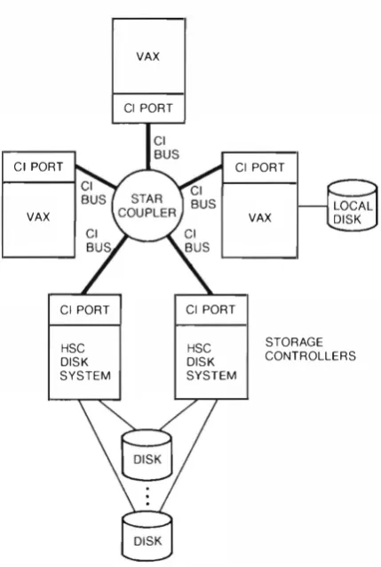
The CI- based VAXcluster SystemFigure
1shows the topology of a typical CI-based
VAXcluster system . The components i nclude the
Cl bus, VAX hosts, Cl ports, and Hierarchical
Storage Controllers (HSC) for mass storage ( i . e . ,
disk and tape) . For high-reliabil i ty applications, a
cluster must contain a minimu m of two VAX pro
cessors and two mass storage controllers w ith
dual-ported devices. The preferred method of
attaching terminals is through a Local Area Trans
port (LAT) server (not shown) , which allows a
terminal to connect to any host in a VAXcluster
system.
The Cl bus is a dual-path serial intercon
nect with each path supporting a transfer rate of
70-megabits per second . The primary purpose of
8
CI PORT
VAX
Cl PORT
HSC DISK SYSTEM
VAX
Cl PORT
Cl PORT
Cl PORT
HSC DISK SYSTEM
VAX
STORAGE CONTROLLERS
Figure 1 VAXcluster Hardware Topology
the dual paths is tO provide redundancy i n the
case of path failure; when both paths are avail
able, they are usable concurrently. Each path is
implemented in two coaxial cables; one for trans
m itted and one for received signals. Baseband sig
naling with Manchester encoding is employed .
Wh i le the C I bus is logically a bus, it is physi
cally organized as a star topology.
A central hub
called the Star Coupler connects all of the nodes
through radial CI paths of u p to 4 5 meters.
The current coupler is a passive device that sup
ports a maximum of 1 6 nodes; node addresses
are 8 bits, providing an archi tectural limit of
2 5 6 nodes.
The selection of a star topology was chosen
over a conventional linear topology for several
reasons. First, the efficiency of a seria l bus is
related to the longest transi t t i me between nodes .
The star permits nodes tO be located within a
4 5 - meter radius (an area of about 6400 square
meters) with a maximum node separation of
90 meter radius (an area of about 6 4 00 square
meters) with a maximum node separation of
90 meters. Typically, a linear bus threaded
through 1 6 nodes in the same area would greatly
exceed 90 meters. Second, the central coupler
provides simple, electrically and mechanically
safe addition and removal of nodes.
The CI port is responsible for arbitration , path
selection , and data transmission . Arbitration uses
carrier sense multiple access (CSMA) but is dif
ferent from the arbitration used by the Ether
net .14·15 Each CI port has a node-specific delay
time. When wishing to transmit, a port waits
until the CI bus is quiet and then waits its
specific delay time. If the CI bus is sti ll quiet, the
node has won its arbitration and may send i ts
packet. This scheme gives priority to nodes with
short delay times. To ensure fairness, nodes actu
ally have two delay times- one relatively short
and one relatively long. Under heavy loading,
nodes alternate between short and long delays.
Thus the bus is contention driven under light
loading and round robin under heavy loading.
Upon winning an arbitration , a port sends a
data packet and waits for receipt of an acknowl
edgment . If the data packet is correctly received ,
the receiving port immediately returns an
acknowledgment packet
withoutre-arbitrating
the CI bus. This action is possible because the Cl
port can generate an acknowledgment in less
time than the smallest node-specific delay.
Retries are performed if the sending CI port does
not receive an acknowledgment.
To distribute transmissions across both paths of
the dual-path CI bus, the CI port maintains a path
status table indicating which paths to each node
are currently good or bad . Assu ming that both
paths are marked good, the CI port chooses one
randomly. This provides statistical load sharing
and early detection of failures. Should repeated
retries fail on a path, it is marked bad in the status
table and the other path is tried.
The Ethernet-based VA.Xcluster System
Figure 2 shows an example of a Local Area VAX
cluster system. The CI bus of Figure 1 has been
replaced by an Ethernet, and the VAX hosts
(referred to as satel lite nodes) are MicroVAX
computers and workstations. Satellite nodes may
be diskless, in which case one or more VAX
hosts act as storage servers, serving a function
analogous to the HSC controllers in CI-based con
figurations. One or more storage servers, cal led
boot nodes, are responsible for load ing satellite
nodes with the VMS operating system and for
stor-Digital Technical journal No. 5 September 1987
ing crash dumps from those nodes. Satellite
nodes may use remote disks for process swapping
and virtual memory backing storage .
The important difference between the Cl
based and the Local Area VAXcluster systems is
t hat the communication functions performed by
the CI hardware are emu lated in the latter by soft
ware within the VMS operating system. The Eth
ernet is an industry-standard, 1 0-megabit per sec
ond baseband local area network'
5that uses the
carrier sense multiple access with collision
detection (CSMA/CD) technique for arbitration .
Unlike the CI bus, an Ethernet may be used to
carry multiple protOcols simultaneously. (Note
that this allows a cluster to share the Ethernet
with other protocols, such as the lAT and DECnet
protocols.)
A new Ethernet protOcol , which is an extension
of SCA, was designed for Local Area VAXcluster
system . Using this protocol , a VMS software com
ponent emulates the Cl port interface, which is
to say that the higher level software interface is
identical to that of the Cl bus, but the Ethernet is
used to carry data . This approach eliminated the
need for any special hardware and allowed the
software modifications needed to be mostly lim
ited to a single VMS component.
Exactly the same approach was used for load
ing the VMS system into satel lite nodes. Here, a
special port emulator was developed to operate
in the booting and system-initialization environ
ment . This boot driver forms part of a vestigial
VMS environment whose function is to read ,
initialize, and start the VMS system i mage from
the remote disk. These modules are themselves
loaded by means of the Digital Network Architec
ture maintenance operations protocol (MOP)
.16The CI
PortArchitecture
Each VAXcluster host and mass storage controller
connects either to the CI bus through a CI port or
to the Ethernet by means of a standard Ethernet
adapter. CI ports have been implemented for the
HSC50 and HSC70 mass storage controllers, and
the VAX- 1 1 /7 5 0, 1 1 /780, 1 1 /7 8 2 , 1 1 /785 , and
VAX 8000 series hosts . Ethernet adapters have
been implemented for all VAX processors. VAX
CI pons i mplement a common architecture,
whose goals are to
•
Off load much of the communications over
head typically performed by nodes in dis
tributed systems
9
The VAXcluster Concept: A n Overview of a Distributed System
• Provide a standard, message-oriented sofnvare
i nterface for both interprocessor communica tion and device control
The design of the CI port is based on the needs of the VMS System Communications Architecture. SCA is a software layer t hat provides efficient communications services to low- level distributed applications (e.g . , device drivers , file services, and network managers) . SCA supports three com mu nications services: datagrams, messages, and block data transfers . In a Local Area VA.,'(cluster system, the SCA functions performed by the CI port are performed by software in the port emula tor modul e .
SCA datagrams and messages are information u n i ts of less than 4,000 bytes sent over a
connec-VAX
VAX
CPU
CPU
VAX
CPU
PORT
PORT
PORT
tion. They differ only i n reliability . The delivery of datagrams is not guaranreed; they can be lost, duplicated, or delivered out of order. The deliv ery of messages is guaranteed, as is their order of arrival . Datagrams are used for status and infor mation messages whose loss is not critical, and by appl ications Jike the DECnet software that have their own high-level reliabil i ty protOcols. Mes sages are used , for example, to carry disk read and write requests.
To simplify buffer a llocation, hosts must agree on the maximum size of messages and data grams that they will transmit. VA.Xcluster hosts use standard sizes of 5 76 bytes for data grams and 112 bytes for messages.
To ensure t he del ivery of messages without duplication or loss, each CI port maintains a
vir-EMULATOR
EMULATOR
EMULATOR
10
ETHERNET
PORT
ETHERNET
PORT
ETHERNET
PORT
---�---�---�---r--- ETHERNET
ETHERNET
PORT
PORT
EMULATOR
[image:12.589.104.502.310.714.2]VAX
CPU
Figure 2 Local Area VAX cluster Topologv
Digital Technical journal
tual circuit with every other remote CI port. A
virtual circuit descriptor table in each port indi
cates the status of its port-to-port virtual circuits.
Included in each virtual circuit descriptor are
sending and receiving sequence numbers. Each
transmitted message carries a sequence number
enabl ing duplicate packets to be discarded .
Block data is any contiguous data in a process'
virtual address space . There is no size l imit
except that i mposed by the physical memory
constraints of the host. The CI port hardware is
capable of copying block data directly from the
process virtual memory on one node to the pro
cess virtual memory on another node. For the Eth
ernet, this function is performed in software by
the port emulator.
The delivery of block data is guaranteed . The
sending and receiving ports and the port emula
tors cooperate in breaking up the transfer into
data packets and ensuring that all packets are cor
rectly transmitted, received, and placed in the
appropriate destination buffer. Virtual circuit
sequence numbers are used on the individual
packets, as with messages. Thus the major differ
ences between block data and messages are the
size of the transfer, and the fact that block data
need not be copied by the host operating system .
Block data transfers are used, for example, by
disk subsystems and disk servers to move data
associated with disk read and write requests.
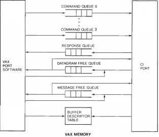
CI Port Interface
The VAX CI port i nterface is shown in Figure 3 .
The interface consists of a set of seven queues:
four command queues, a response queue, a data
gram free queue, and a message free queue. The
queues and queue headers are located in host
memory. When the port is initialized , the host
software loads a port register with the address of
a descriptor for the queue headers.
Host software and the port communicate
through queued command and response packets.
To issue a port command , the port driver software
queues a command packet to one of the four com
mand queues. These four queues accommodate
four priority levels; servicing is FIFO within each
queue.
Anopcode within the packet specifies the
command to be executed . The response queue is
used by the port to enqueue incoming messages
and datagrams, while the free queues are a
source of empty packets for incoming messages
and a sink for transmitted message packets.
For example, to send a datagram, software
queues a SEND DATAGRAM packet onto one of
COMMAND QUEUE 0
VAX PORT SOFTWARE
I I l
COMMAN D QU EUE 3
I I I
R ESPONSE QU EUEI I I
I
DATAGRAM FREE QUEUEI I I
t
I
MESSAGE FREE QUEUEI I I
t
BU FFER DESCRIPTOR TABLE
VAX MEMORY
Figure 3 The CJ Port Interface
Cl
PORT
Digital Technical journal
l l
No. 5 September 1987
[image:13.587.132.446.433.702.2]The VAXcluster Concept: An Overview of a Distributed System
FORWA R D L I N K
BACKWA R D L I N K
OPCODE
I
PORTI
STATU SDATAGRAM LENGTH
[image:14.589.72.289.99.299.2]DATAGRAM TEXT
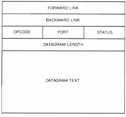
Figure 4 CI Port Command jacket
the command queues. The packet contains an
opcode field specifying SEND DATAGRAM , a port
field with the destination port number, the data
gram size , and the text of the datagram. The
packet is doubly l inked through its first two
fields. This structure is shown in Figure
4 .
If the host software needs confirmation when
the packet is sent, it sets a response queue bit in
the flags field. This bit causes the port to place
the packet in the response queue and interrupts
the host after the packet has been transmitted.
The response packet is identical to the SEN D
DATAGRAM packet, except that the status field
indicates whether or not the send was successful.
Had the response queue flag bit been clear in t he
SEND DATAGRAM command (as it typically is),
the port would instead place the transmitted
command packer on the datagram free queue
without causing a host interrupt.
Upon receiving a datagram , a CI port takes
apacket from its datagram free queue . Should the
queue be empty, the datagram is discarded . Oth
erwise, the port constructs a DATAGRAM
RECEIVED packet that contains the datagram and
the port number of the sending port. This packet
is then queued on the response queue.
Messages operate in a similar fashion, except
that they have a different opcode, and the mes
sage buffers are dequeued from the message free
queue . If the message free queue is empty when
a message arrives, the port generates an error
interrupt to the host. The high-level SCA flow
12
control ensures that the message free queue does
not become empty.
Block transfer operations are somewhat more
complicated . Each port has a data structure
calle<J a buffer descriptor table. Before perform
ing a block transfer, host software creates a buffer
descriptor that defines the virtual memory buffer
to be used . The descriptor contains a pointer to
the first VAX page table entry mapping t he virtu
ally contiguous buffer. In addition, the descrip
tor contains the offset (within the first page) of
the first byte of the buffer, the length of the
buffer, and a 16-bit key. The data structures for a
block transfer are illustrated in Figure 5 .
Each buffer has a 32-bit name, consisting of
a 16-bit buffer descriptor table index and the
16-bit buffer key. The key is used tO prevent dan
gling references and is modified whenever a
descriptor is released. To transfer block data , the
initiating software must have the buffer names of
the source and destination buffers. The buffer
names are exchanged through a high level mes
sage protocol . A host can cause data to be moved
either ro another node (SEND DATA) or from
another node (REQUEST DATA) . A SEND DATA or
REQUEST DATA command packet contains the
names of both buffers and the length of the trans
fer. In either case (send or request) , a single
command packet causes the source and destina
tion ports to perform the block transfer. When
the last packet has been successfully received,
the initiating port places a response packet on its
response queue, indicating that the transfer is
complete .
The goal of reducing VAX host interrupts is met
through several strategies and mechanisms. First,
the block transfer mechanism minimizes the
number of interrupts necessary to transfer large
amounts of data . Second, at t he sending port,
DATAGRAJVI SENT/MESSAGE SENT confirmation
packets are typically generated only when a fail
ure occurs . Third, a receiving port interrupts the
VAX host only when the port queues a received
packet on an empty response queue . Thus when
software dequeues a packet in response to an
interrupt, it always checks for more packets
before dismissing t he interrupt.
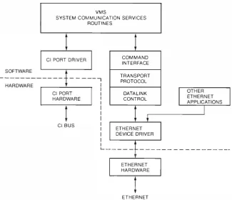
Port Emulation for the Ethernet
Figure 6 shows the relationship of the port emu
lator to the VMS operating system functions that
usc that emulator. For comparison, the CI port
interface is a lso shown in this diagram . The port
emulator implements the same functions as the
Cl BUS
1\
Cl PORTCOMM'""
I
QUEUE\ '"""'
I � I I I
DESC R I PTOR PAGE�
TABLE TABLEQU EUE LINKS FLAGS
I
OPCODEI
DESCRIPTORPORT NO.
I
STATUS TRANS. SIZESOU RCE BUFFER NAME
DEST. BUFFER NAME
BLOCK TRANSFER PORT COMMAND
[image:15.587.124.450.364.644.2]HOST MEMORY
Figure 5 CI Port Block Data Memory Mapping
VMS
SYSTEM COM M U N ICATION SERVICES ROUTINES
C l BUS
COM MAND INTERFACE
TRANSPORT PROTOCOL
DATALINK CONTROL
ETHERNET
Figure 6 CI Port Emulation Using Ethernet
PAGES
Digital Technical journal 1 :�
No. 5 September 1 987
The VAXcluster Concept: A n Overview of a Distributed .�)'stem
emulator implcmt:nts the same functions as the
CI port and its associated driver. The emulator
also operates the SCA protocol across the Ether
net and manages i ts interface with the Ethernet
datalink driver. Thus the emulatOr is responsible
for
•
The provision of a compatible command int er
face tO the system communication services
(SCS) module
•
The operation of a transport protOcol that imi
tates CI behavior
•
Node authentication and topology control
functions
•
Propagation of Ethernet datagrams and data
link control
The port emu latOr must deal with an underly
ing datal ink layer whose characteristics are some
what different than those of the CI bus. The Eth
ernet datalink can transmit datagrams between
64 and I , 5 36 bytes in length in either a point-to
point, multicast, or broadcast fashion . The Ether
net provides neither automatic acknowledgment
nor flow control , and Ethernet adapters do not
handle either buffer segmentation or d i fferent
message types. The CI functions of datagram
transmission , sequenced messages, and block
transfers must be implemented by the e mu lator
and translated into requests that can be p ro
cessed by the standard VMS Ethernet device
drivers .
Port emu lation can be viewed conceptually as
three separate layers . The highest layer provides a
command interface for the higher level SCS rou
tines . That interface is compatible with that used
for CI ports . This layer is also responsible for tht:
fragmentation and re-assembly of block transfer
buffers that are larger than the maximum Ether
net message size.
The transport layer provides a sequenced nlCs
sage and datagram service ro the correspond i ng
layer in the remote node. Its hand l ing of data
grams amounts to l i trle more than a pass-through
function ; the hand! ing of sequenced messages
and block transfers, however, is more complex.
ln the latter case, the transport layer must t:nsure
that messages are transmi tted and received in the
correct order, ensure that acknowledgments arc
sent and received, and retransmit messages that
have been lost. The transport layer operato a
simp k pipeline flow control scheme that a l l ows
a fixed window of unacknowledged messages.
Acknowledgments can be " piggybacked"
onrt:turning messages.
1 4
Last. the datali n k control layer is responsible
for passi ng messages between the Ethernet device
clrivns and the transport layer and control of the
Ethernet data link service . The datal ink control
layer also maintains a record of t he cluster's
topol ogy by exchanging mu lticast messages with
other cl uster members .
Below the port emulator module is tht: stan
dard VMS Ethernet device driver, which can also
be ust:cl simultaneously by other applications l i ke
the DECnet,
LAT.and ISO transport protocols.
These protocol<> are mu ltiplexed and demu lti
plcxed by the Ethernet device driver using the
Ethernet standard p rotocol type.
The
C lport emulation function for the Local
Area VAXcluster system has a h igher system
ovnhcad than the equivalent CI connection
si nct: the operations i nvolved are performed by
tht: host VAX processor. Since the Ethernet has
lower bandwidth and longer response ti mes.
however, the demand for host system resources
is moderated . The Local Area VAXcluster per
formance is acceptable for typical customer
work loads in which most nodes are single-user
workstations. The CPU t i me overheads are most
noticeable on nodes that serve disks to multiple
users; those nodes are typical ly dedicated
proct:ssors .
Mass Storage Control
·rhe move from control- and status register
activatt:cl storage devices to message-oriented
storage devices offers several advantages:
•
Sharing is simplified si nce several hosts can
queue messages to a single controller. In add i
tion , device control messages can be transmit
ted to and executed by hosts with local disks.
•
Extension to new devices is easier. In contrast
toconwntional systems where there is a differ
ent drivn for every type of d isk and disk
i nterface, a single d isk class driver si mply
bui l ds mt:ssage packets and transmits them
using a communications i nterface. The disk
class driver is independent of drive specifics
( e . g , cy l inders and sectors) . New d isk and
tape devices ancl controllers can be added with
I
i ttk or no modi fication to the host software .
•
Performance is improve d . The controller can
mainta i n
aq u eue of requests from mu ltiple
hostsand can opt i m i ze disk performance in
rt:a l time. The control ler can also hand le error
rt:covt:ry and bad-block replacement.
Digital Technicaljournal
The HSC fam i ly, shown i n Figu re 1 , is a CI
based controller for both disks and tapes . A single
HSC70 control ler can hand le up to 32 disk
drives. Multiple HSC control lers with dual
ported d isks provide redundancy in case of fail
ures. Further redundancy can be provided by
grouping disk volumes rogether in shadow sets to
form a single virtual vol u me in which a l l mem
bers contain exactly the same data . If one mem
ber of the shadow set fai ls, the virtual disk vol
ume continues t O b e available.
The protocol interpreted by the HSC controller
is called t he Mass Storage Control Protocol
(MSCP) , which provides accl:ss to mass storagl"
vol uml:s at the logical block kvd . The MSCP
VAX 1
PROCESS
FILE RECORD
MGMT. MGMT.
model sl:paratl"S the tlow of control and status
information
fromthe tlow of data . This d istinc
tion has been used in other systems to achieve
efficient fi le access
1 7and corresponds to the
CIport's message and block data mechanisms; mes
sages arc used for device control commands
whi l e block transfers are used for data .
The same control protocol is used tO provide
clusterwide access
tOCI-based controllers l i ke
the HSC devices, and tO disks connected directly
to
a VAX processor (See Figure 7 ) . In a Loca l Area
V�'Cclustcr system , all mass storage is connected
directly to the boot node and to zero or more
other storage server nodes. Messages arc routed
from the d isk class driver in the requesting node
VAX 2
PROCESS
FILE RECORD MGMT. MGMT.
DISK CLASS DR IVER
LOCK MANAGER
DISK CLASS DRIVER
LOCK MANAGER
MSCP DISK SERVER
DISK PORT DRIVER
SCA SOFTWARE SCA SOFTWA R E
LOCAL DISKS
Cl BUS
---�---�---�---
ORETH ERNET
HSC
(CI BUS ONLY) SCA SOFTWARE
[image:17.587.62.507.275.716.2]DISKS
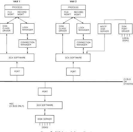
Figure 7 VAXcluster Software Structure
Digital Technical journal 1 ')
No. 5 September 1 987
The VAXcluster Concept: A n Overview of a Distributed System
to an MSCP server on the node with the local
disk. This server then parses the MSCP message,
issues requests to its disk, and initiates the block
transfer through i ts SCA interface . Thus in either
a CI-based or a Local Area VAXcluster system , all
locally attached disks can be made transparently
available to all other VAX hosts in the cluster.
VAXcluster Software
From a user's point of view, a VAXcluster system
is a set of nodes cooperating through the VAX/
VMS distributed operating system software to
provide sharing of resources among users on all
nodes . Shared resources include certain devices,
fi les, records within files, and system batch and
print queues. Typically, user account and pass
word information resides i n a single file shared
by all cluster nodes. A user obtains the same
environment (files, default directory, privileges,
etc.) regardless of the node to which he or she is
logged into. In many respects, the VAXcluster
system " feels" like a single system to the user.
This sense of a single system results from the
fact that the VAXcluster system is symmetrical
with respect to the participating VAX processors .
In other words, there is no specialization of func
tion designed into the sofrware (although an
installation may choose to configure certain
CPUs differently according tO the special needs
of that installation) . The VMS and VAXcluster file
system architecture is based on the concept of
clusterwide and uniform logical block access to
the mass storage managed by a distributed file
system . This concept contrasts with fil e server
based distributed systems.
Figure 7 shows an example of a small VAXclus
ter system and some of its major sofrware compo
nents. Note that the operation of the VMS soft
ware in the VAXcluster environment is exactly
the same for both Local Area and CI-based VAX
cluster systems. The diagram shows an underly
ing interconnect that may be either the
crbus or
the Ethernet, both of which use the port interface
methods described above. HSC disk control l ers
connect only to the Cl bus.
At the highest leve l , multiple user processes on
each node execute in separate address spaces .
File and record management services are imple
mented as procedure-based code within each
process . The fil e and record services rely on
lower level primitives, such as the lock man
ager18 and disk class driver. The lock manager is
the foundation of all resource sharing in both
1 6
clustered and single-node VMS systems. I t pro
vides services for naming, locking, and unlocking
clusterwide resources. The disk class driver,
mentioned earlier, uses the MSCP to communi
cate with disk servers. The disk class driver runs
in both clustered and nonclustered environments
and contains no knowledge of the VAXcluster
configuration . SCA software below the driver is
responsible for routing driver messages to the
correct device control ler.
A distributed connection manager is responsi
ble for coordinating the cluster. Connection
managers on all cluster nodes collectively decide
upon cluster membership, which varies as nodes
leave and join the cluster. Connection managers
recognize recoverable failures in remote nodes;
they a lso provide data transfer services that han
dle such failures transparent to higher software
levels.
Form ing a Cluster
A VAXcluster system is formed when a suffi
cient set of VAX nodes and mass stOrage resources
becomes available . New nodes may boot and join
the cluster, and members may fai l or shut down
and leave the cluster. When a node leaves or
joins, the process of reforming the cluster is
cal led a cluster transition . Cluster transitions are
managed by the connection managers.
In an operating cluster, each connection man
ager has a list of all member nodes. The l ist must
be agreed upon by all members. A single node
can be a member of only one VAXcluster system ;
in particular, the same resource (such as a disk
controller) cannot be shared by two clusters or
the integrity of the resources coul d not be guar
anteed. Therefore , connection managers must
prevent the partitioning of a cluster into two or
more clusters attempting co share the same
resources.
To prevent partitioning, the VMS system uses a
quorum voting scheme . Each cl uster node con
tributes
anumber of votes, and the connection
managers dynamically compute the total votes of
all members. The connection managers also
maintain a quorum value. As transitions occur,
the cluster continues to run as 1long as the total
number of votes present equals or exceeds the
quorum . Should the total number of votes fal l
below the quorum , the connection managers wil l
suspend VAXcluscer activity. When a node joins
and brings the total votes up to the quorum , clus
ter activity will resume .
Digital Technicaljournal
A c l uster member may have a recoverable error
in its communications. Such an error leaves the
node's memory i ntact and al lows the operating
system to continue running after the error cond i
tion has disappeared . These errors can cause ter
mination of a virtual circuit and a corresponding
loss in communication . When cluster members
detect the loss of com mu n ication with a node,
they wait for a short period (specified by the sys
tem manager) for the fai l i ng member to re-estab
l ish contact. If the fai li ng member recovers
within this period, it rejoins the cluster. Users
may experience a brief interruption of service
when this happens. If the fai ling member docs
not recover in time , the surviving members
remove the fai led node from the cluster and con
tinue operating (assuming sufficient votes arc
present) . A node that recovers after it has been
removed from the cluster is told to re-boot by the
connection managers.
Shared Files
The VAXcluster system provides a clusterwide
shared fi le system to i ts users. 1 9 Cluster accessi
ble files can exist on CI-based disk controllers or
on disks local to any of the cluster nodes. Each
cl uster disk has a unique and location-indepen
dent name . A complete cluster fi le name includes
the disk device name , the d irectory name, and the
fi le name. Using the device name for a fi le, the
cluster software can locate the node (either a
CPU or a d isk controller) on which the fi le
resides .
Cluster fi le activity requ i res synchronization ;
exclusive-write fi le opens, coord i nation of fde
system data structures, and management of fi le
system caches arc a few examples. However,
despite the fact that files can be shared cluster
wide, the fi le management services are largely
unaware of whether they are executing in a clustered environment. These fi le managers synchro
nize through the VMS lock manager, described
later. The lock manager hand les the locking and
unlocking of resources across the cluster. At the
l eve! of the fi le manager, then, cluster fi le
sharing i·s simi Jar to single-node file sharing.
lower levels hand le the clustcrwidc synchroniza
tion and routing of physical-level disk requests to
the correct device .
Distributed Lock Manager
As
previously described , the VMS lock manager is
the basis for clusterwide synchronization . Severa l
Digital Technical journal No. 5 September I 987
goa ls influenced the design of the lock manager
for a distributed environment. First , programs
using the lock manager must run in both single
node and cluster configurations. Second , lock
services must be efficient to support system- level
software that makes frequent short-duration
accesses. Therefore , i n a VAXcluster system , the
lock manager must minimize the number of SCA
messages needed to manage locks. In a single
node configuration , the ,Jock manager must rec
ognize the simpler environment and bypass any
c l uster-specific overhead. Finally, the lock man
ager must recover from fai lu res of nodes holding
l ocks so that surviving nodes can continue to
access shared data i n a consistent manner.
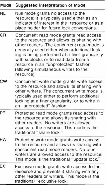
The VMS lock manager services al low cooper
ating processes to define shared resources and
synchron ize access to those resources. A resource
can be any object an application cares to define.
Each resource has a user-defined name by which
it is referenced . The lock manager provides basic
synchronization services to request and release
locks. Each lock request specifics a locking
mode, such as exclusive access, protected read,
concurrent read, and concurrent write . If a pro
cess requests a lock that is incompatible with
existing locks, the request is queued unt i l the
resource becomes avai lable. In many applica
tions, resources may be subdivided into a
resource tree, as i l lustrated in Figure 8 .
FILE 1
DISK VOL U M E
F I L E 2 FILE 3
�
RECORD 1 RECORD 2
Figure 8 VAXcluster Locking Structure
In this example, the resource Disk Vol u me
contains resources Fi le
Ithrough Fi le 3 ; resource
File 3
contains resources Record
1 ,Record 2 , and
so on . The first locking request for a resource can
specify the parent of that resource, thereby defin
ing its relationship in a tree. A process making
several global changes can hold a h igh-level l ock
(e.g . , the root) a nd can make them all very effi
cient ly. A process making a smal l , low-level
change ( c .g . , a leaf) can do so whi lc stiH per
mitting concurrent access to other parts of the
tree.
201 7
The VAXcluster Concept: An Overview of a Distributed System
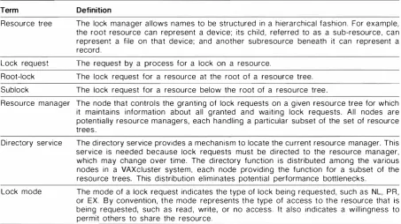
The lock manager's implementation is in
tended to d istribute the overhead of lock man
agement throughout the c luster while s t i l l mini
mizing the internode traffic needed to perform
l ock services. The database is therefore divided
into two parts: the resource lock descriptions,
and the resource lock directory syste m , both of
which arc d istributed. Each resource has a master
node responsible
forgranting locks on the
resource ; the master mainta i ns a l ist of granted
locks and a queue of waiting requests for that
resource . The master for a l l operations for a sin
gle tree is the node on which the l ock request for
the root was made . While the master mainta i ns
the l ock data for i ts resource tree , any node hold
i ng a lock on a resource mastered by another
node keeps its own copy of the resource and lock
descri ptions.
The second part of the database , the resource
d irectory system , maps a resource name i nto the
name of the master node for that resource . The
directory database is d istributed among nodes
wil l ing to share this overhead . Given a resource
name, a node can trivia ll y compute the responsi
ble directory as a function of the name string a nd
the number of d irectory nodes.
To l ock a resource in a YA.Xcluster system , the
lock manager sends a lock req uest message
through the SCA to the d i rectory for t he resource .
The directory responds i n one o f three ways:
1 .
If l ocated on the master node for the
tfll,
�
ource
,
the d irectory performs the lock
��
J,y
6
request and sends a confirmation response to
the requesting system .
2 .
I f the directory i s not o n the master node hut
finds the resource defined , it returns a
response containing the identity of the mas
ter node.
3.
I f the d i rectOry finds the resource to be
undefi ned, it returns a response tel ling the
requesting node to master the resource
i tsel f.
In the best cases
( land 5 ) , two messages arc
required to request a lock; case
2takes four mes
sages. An u n l ock is executed with one message . lf
the lock request is for a subrcsource in a resource
tree, the requesting process wi l l e ither be
located on the master node ( i . e . , the request is
local) or will know who the master for its parent
is, allowing it to bypass the directory looku p . In
a l I cases the number of messages required is
1 8
independent
ofthe number of nodes in the VAX
cluster system .
I n addition t o standard .locking services, the
lock manager supports data caching in a dis
tri buted environment. Depend ing on the fre
quency of modifications, caching of shared data
in a distributed system can substantially reduce
the I/0 and commun ications workload .
A I 6-byte block of information , cal led a va lue
block, can be associated with a resource when
the resource is defined to the lock manager. The
val u e in the value block can he mod i fied by a
process releasing a lock on the resource and can
be read by a process when it acq u i res ownership.
Thus this information can be passed a long with
the resource ownership.
In the case of a fil e buffer, for example, a ver
sion nu mber is mainta i ned i n the value block.
When caching a buffer, a process saves the cur
rent version number. To mod i fy the buffer , the
process obtains an exclusive l ock and receives
the current version number. If the current ver
sion number equals the version number of the
cached data , the cache is val i d . Several u pdates
can then be made on the cached data before it is
written back tO disk. When the modified data is
written , the process incre ments the version num
ber and rel eases its lock.
Another mechanism used in buffer caching is a
software i nterrupt mechanis m . When requesting
an exc lusive lock, a process can specify that it
shou ld be notified if a nother lock request on the
resource is forced ro block. A process can then
hold a modified copy of the data without writing
it back. When another process wants access, the
owner wri tes the modified data and releases irs
l ock.
In the case of cl uster transi tions (e.g . , fai l u re
of a node ) , the connection manager notifies the
lock manager that a transition has started . Each
lock manager performs recovery action , and a l l
lock managers must complete this activity before
cl uster operation can continue.
As