A Novel Excessive Overall Performance Three
Phase Reduced Switch depend Power Converter for
Induction Machine Drive Application
Kota Nayak. V
Assistance Professor, Electrical and Electronic Department, Dhruva Institute of Engineering and Technology Hyderabad, Telangana State, India
Abstract: Single-phase to 3-phase conversion the usage of strength electronics converters is a famous technology, specifically whilst the configurations and manage strategies already set up inside the technical literature are considered. Concerning the configurations conceived over the years, it can be located two primary inclinations: 1) configurations with a reduced variety of components; and 2) configurations with an multiplied number of additives. The look for topologies with a discounted wide variety of additives changed into the trend over a protracted time period. This may be, in element, defined by means of the high fee of the strength transfer when compared to the capacitor used within the dc-hyperlink bus. Then, the converter leg becomes once in a while substituted for the midpoint capacitor. however, as a long way because the price of the semiconductor turned into taking place, such tendency has been changed, and now the configurations with an elevated number of components do seem as an interesting option, particularly in phrases of reliability, performance, and distortions improvement.
I. INTRODUCTION
The use of induction motors (IMs) are increasing day by day in industry sector for high power applications. The main advantages of IMs are rugged in construction, easy maintenance, less cost and sufficiently high efficiency, etc. Speed control of IM requires a suitable inverter to change the voltage and frequency applied to it. Normally we do two stage conversion, i.e. convert the ac power from supply mains to dc (rectification) and then it is converted to again ac (inversion) to control the speed of the machine. Generally we use a voltage source inverter (VSI) for this job. But the conventional H- bridge VSI produces a square wave output voltage waveform which contains infinite number of odd harmonics in [1]. For getting the sine wave output we prefer PWM based inverter, but the main disadvantage of PWM inverter is switching losses are high and also it is limited to low power applications. For medium and high power applications, we are using single phase to three phase with single stage conversion.
Power electronic converters use active semiconductors (e.g. IGBTs) and passive power semiconductors (e.g. diodes) and passive elements (e.g. inductors and capacitors) arranged in circuit structures to convert power from the form available from a source to that required by a load. The power source may be a DC source, a single–phase AC source, or a three-phase AC source with line frequency of 50, 60 or 400 Hz. It may also be an electric battery, a solar panel, an electric generator or a commercial power supply. The source feeds the input of the power converter, which converts the input power to the required form for a load. The load may be DC or AC, single–phase or three–phase, and may or may not need transformer isolation from the power source. The power converter, therefore, can be an AC/DC converter, a DC/DC converter, a DC/AC inverter or an AC/AC converter depending on the application [2].
The main focus of the research in this thesis has been on three-phase AC-AC power converters. These are converters that convert a single-phase input voltage into an three phase output voltage. The three- phase AC voltage is typically obtained from the conversion and applied to control the speed of induction machine drive. AC-DC power converters connected to the mains voltage can generate and inject current harmonics into the utility mains. Injecting current harmonics into the AC mains results in two significant consequences:
1) First, because of the finite impedances of the power lines, harmonic currents generate voltage variations at the point of common coupling that other equipment on the line must tolerate.
2) Second, although current harmonics do not generate real power, they must be considered in the design of power lines so that power lines must be significantly overrated lest they overheat.
To minimize the harmonics generated by power converters, power factor correction (PFC) techniques have been developed so that the generated harmonics comply with regulatory agency standards such as IEC 61000-3-2 Class A. Power factor (PF), which is a measure of how effectively the input AC source is used can be defined as
(1) Where P is the output real power, Vll, rms is the three-phase line-line rms voltage and Irms is the input rms line. A power factor of 1 is the maximum power factor that can be achieved and represents the most efficient use of the input AC source. AC-DC/AC power converters implemented with PFC techniques are made to operate in such a way that their input currents are shaped so that they are sinusoidal and in phase with their respective phase voltages. Most AC-DC/AC power converters today that are supplied by the AC mains are implemented with some sort of PFC technique and the implementation of PFC in power electronic converters is a very relevant research topic in the power electronics field. On the other hand, loads connected in a three phase arrangement present some advantages when compared to single-phase loads. This is especially true when motors are considered [3], [4], due to their constant torque, constant power, reduced size, etc. There is a need for single- phase to three phase conversion systems in this scenario. In terms of application, the first thing that comes to mind when it is considered a single-phase to three-phase conversion, it is a three-phase motor drive system. However, the [5] claim that, in rural application, feeding a three-phase induction motor is not anymore the main concern for the single-phase to three-phase conversion have been done in this paper and evaluated by using Matlab/Simulink Tool.
II. PROPOSED SINGLE PHASE TO THREE PHASE CONVERSION SCHEME
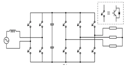
Two configurations will be considered as conventional ones, as observed in Fig. 1. It is worth to mention that each configuration will be renamed in this work in order to facilitate the comparison: e.g., Fig. 1 (a) will be called as C1, Fig.1 (b) will be called as C2, and so on. Configuration C2 [see Fig. 1(b)] represents an interesting solution for single-phase to three-phase power conversion, since all variables at input–output converter sides can be controlled, as observed in Fig. 2, while the configuration C1 represents a cheaper solution but without any control of the input current and dc-link voltage. Fig. 2 and Fig.3 shows the results for configurations C1 and C2, respectively. It is worth to mention that these two configurations are considered as the reference for the new proposals, i.e., the new topologies aim to generate waveforms closer of the configuration C1 and far away of the configuration C2.
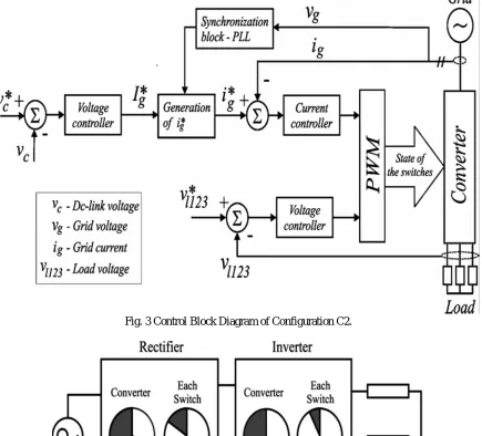
A suitable control strategy employed to guarantee the control objectives of the configuration C2 is depicted in Fig. 4. The variables with “*” in this figure mean the reference variables. Notice from this figure that there exist three controllers and a synchronization block. Such control strategy will be considered as a reference to establish a figure of merit regarding the control complexity. Other important characteristic observed in the single-phase to three-phase power converters which also has been considered in this work the irregular distribution of power among the switches of the converter, as observed in Fig. 5. It means that 63% of the total losses measured in the single-phase to three-phase converter [see Fig. 1(b)] is concentrated in the rectifier circuit, while the rest 37% is observed in inverter circuit.
(a)
(9
Single (99(p
[image:4.612.173.432.105.242.2](b)
Fig. 1 Conventional single-phase to three-phase configurations (a) Diode bridge in the input converter side (C1). (b) Controlled rectifier in the input converter side (C2).
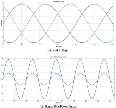
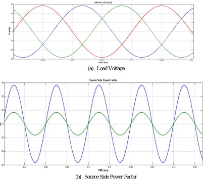
(a) Source Side Power factor
[image:4.612.89.520.299.643.2](b) Load Voltage
Fig. 2b Simulation results of the conventional single phase to three-phase power conversion of Configuration C2.
Fig. 3 Control Block Diagram of Configuration C2.
Fig. 4 Converter power losses distribution in both rectifier and inverter units: 63% in the rectifier circuit and 37% in the inverter one. Power losses in each switch of the rectifier (15.7%) and inverter (6.1%)
III. CONVERTER WITH REDUCED SWITCH COUNT
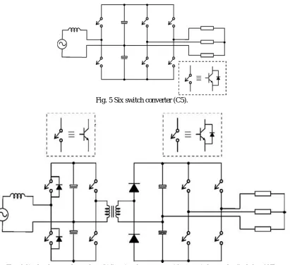
Fig. 5 Six switch converter (C5).
Fig. 6 Single-phase to three-phase bidirectional converter with six switches and a diode leg (C7).
The authors in [11]-[15] employ a synchronization technique to reduce the capacitor current in the dc link; this technique was applied when the output frequency is equal to the input one. This circuit operates as a soft-switched ac–dc–ac with high-frequency isolation, as observed in Fig. 6. Its main characteristics are operation with zero-voltage switching, power factor control, and reversible power flow. A single-phase to three-phase converter with six switches and a diode leg is presented in [17] (see Fig. 6).
IV. INCREASED NUMBER OF SWITCHES
Fig. 7 Parallel ac–dc–ac single-phase to three-phase converter
V. MAT LAB/SIMU LINK MODELING AND RESULTS
Here simulation is carried out in several cases in that,
1) Proposed Single-Phase to Three Phase C1 Configuration 2) Proposed Single-Phase to Three Phase C2 Configuration 3) Proposed Single-Phase to Three Phase C5 Configuration 4) Proposed Single-Phase to Three Phase C28 Configuration
5) Proposed Single-Phase to Three Phase C5 Configuration Applied to Three Phase Induction Machine Drive.
[image:7.612.49.562.433.667.2]A. Case 01: Proposed Single-Phase to Three Phase C1 Configuration
Fig. 8 Matlab/Simulink Model of Proposed Single Phase to Three Phase C1 Configuration
(a) Load Voltage
[image:8.612.143.470.76.351.2](b) Source Side Power Factor
Fig. 9 Source Side PF & Output Voltage of Proposed Single Phase to Three Phase C1 Configuration
Fig.9 Shows the Source Side PF & Output Voltage of Proposed Single Phase to Three Phase C1 Configuration, in this configuration prefer single phase input source fed to uncontrolled rectifier and interfaced to three phase six switch VSI topology through DC link Capacitor.
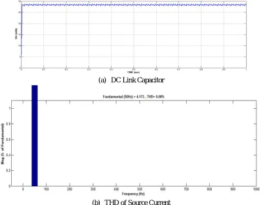
(a) DC Link Capacitor
(b) THD of Source Current
[image:8.612.118.491.422.716.2]Fig.10 DC Link Voltage & THD of Source Current of Proposed Single Phase to Three Phase C1 Configuration here maintain DC link voltage as a constant and the Source Current THD will be very low within the IEEE/IEC standards.
[image:9.612.58.513.124.248.2]B. Case 02: Proposed Single-Phase to Three Phase C2 Configuration
Fig. 11 Matlab/Simulink Model of Proposed Single Phase to Three Phase C2 Configuration
Fig. 11 shows the Matlab/Simulink Model of Proposed Single Phase to Three Phase C2 Configuration with the help of MATLAB/SIMULINK Platform.
(a)Load Voltage
(b) Source Side Power Factor
Fig. 12 Source Side PF & Output Voltage of Proposed Single Phase to Three Phase C2 Configuration
[image:9.612.114.500.301.660.2](a) DC Link Capacitor
[image:10.612.139.467.79.363.2](b) THD of Source Current
Fig. 13 DC Link Voltage & THD of Source Current of Proposed Single Phase to Three Phase C2 Configuration
Fig.13 DC Link Voltage & THD of Source Current of Proposed Single Phase to Three Phase C2 Configuration here maintain DC link voltage as a constant and the Source Current THD will be very low within the IEEE/IEC standards.
[image:10.612.62.550.444.679.2]C. Case 03: Proposed Single-Phase to Three Phase C28 Configuration
Fig. 14 Matlab/Simulink Model of Proposed Single Phase to Three Phase C28 Configuration
(a) Load Voltage
[image:11.612.139.477.81.366.2](b) Source Side Power Factor
Fig. 15 Source Side PF & Output Voltage of Proposed Single Phase to Three Phase C28 Configuration
Fig.15 Shows the Source Side PF & Output Voltage of Proposed Single Phase to Three Phase C28 Configuration, in this configuration prefer single phase input source fed to uncontrolled rectifier and interfaced to three phase six switch VSI topology through DC link Capacitor.
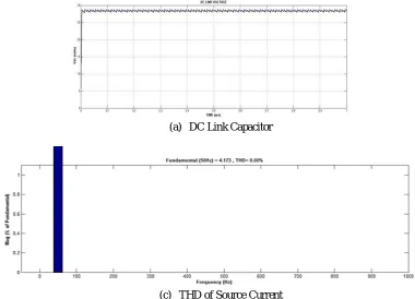
(a) DC Link Capacitor
(c) THD of Source Current
[image:11.612.113.493.448.722.2]Fig.16 DC Link Voltage & THD of Source Current of Proposed Single Phase to Three Phase C28 Configuration here maintain DC link voltage as a constant and the Source Current THD will be very low within the IEEE/IEC standards.
[image:12.612.93.520.129.262.2]D. Case 04: Proposed Single-Phase to Three Phase C5 Configuration
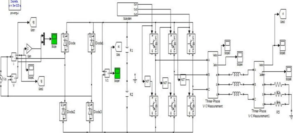
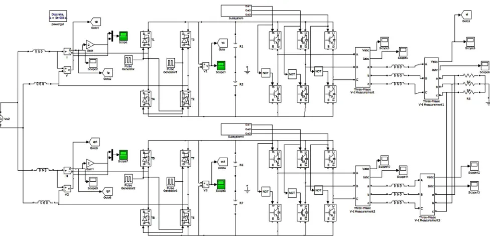
Fig. 17 Matlab/Simulink Model of Proposed Single Phase to Three Phase C5 Configuration
Fig. 17 shows the Matlab/Simulink Model of Proposed Single Phase to Three Phase C5 Configuration with the help of MATLAB/SIMULINK Platform.
(a) Load Voltage
(b) Source Side Power Factor
Fig. 18 Source Side PF & Output Voltage of Proposed Single Phase to Three Phase C5 Configuration
[image:12.612.105.509.316.670.2](a) DC Link Capacitor
[image:13.612.106.503.59.406.2](b) THD of Source Current
Fig. 19 DC Link Voltage & THD of Source Current of Proposed Single Phase to Three Phase C5 Configuration
Fig.19 DC Link Voltage & THD of Source Current of Proposed Single Phase to Three Phase C5 Configuration here maintain DC link voltage as a constant and the Source Current THD will be very low within the IEEE/IEC standards.
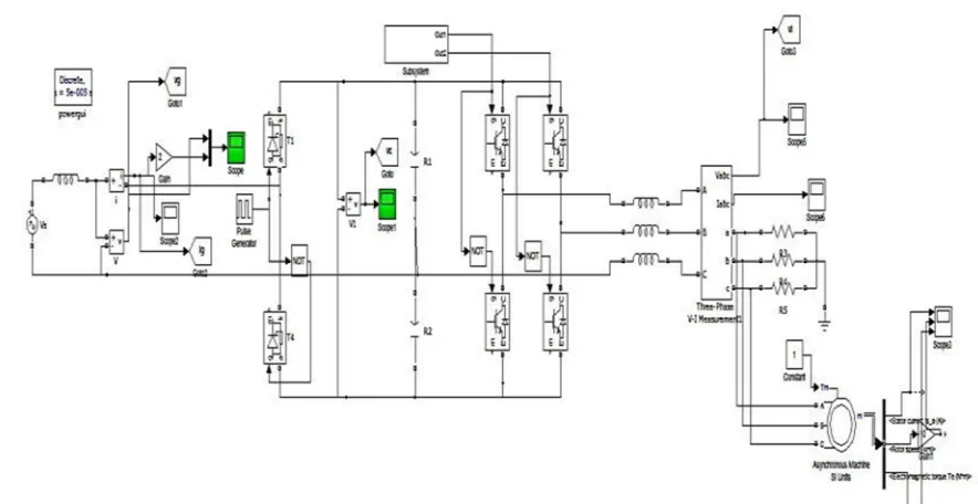
E. Case 05: Proposed Single-Phase to Three Phase C5 Configuration Applied to Three Phase Induction Machine Drive
[image:13.612.78.520.482.710.2]Fig.20 shows the Matlab/Simulink Model of Proposed Single Phase to Three Phase C5 Configuration with Induction Machine Drive, to update the characteristics of the induction machine by using optimal switching technique and circuit configuration.
Fig. 21 Stator Currents, Speed, Electromagnetic Torque of Proposed Single Phase to Three Phase C5 Configuration with Induction Machine Drive
Fig. 21 shows the Stator Currents, Speed, Electromagnetic Torque of Proposed Single Phase to Three Phase C5 Configuration with Induction Machine Drive, at starting induction machine have high starting torque and after running may get low torque, to drive the high speed condition.
VI. CONCLUSION
Modern power electronic inverters are based on PWM strategies with switches characterized by very small switching times. As a consequence, the motor windings are subjected to a completely huge amount of HF voltage components. With the improvement of superior power digital switching gadgets, the high-frequency switching operation has been enabled, and the performance of pulse width modulation (PWM) inverters for riding induction automobiles has been advanced significantly. The suggestion of this work was to provide a country of the artwork for unmarried-segment to three-phase conversion gadget, displaying the maximum essential configurations and their characteristics. It turned into located two foremost inclinations through the years, i.e., configurations with reduced range of components and configurations with expanded range of components. The configurations with accelerated range of additives (C28) are an thrilling alternative for unmarried-segment to a few phase structures because of its inherent traits, including THD enhancements, high reliability, and efficiency. Moreover, it's miles feasible to resolve a specific trouble observed in single-phase to 3-single-phase systems, i.e., dc-link voltage fluctuation. Here proposed C5 configuration have excessive better functions in comparison to all different topologies used in many business packages.
REFERENCE
[1] B. Saint, “Rural distribution system planning using smart grid technologies,” in Proc. IEEE Rural Electr. Power Conf., Apr. 2009, pp. B3–B3-8
[2] H.-C. Chen, “Single-loop current sensorless control for single-phase boost-type SMR,” IEEE Trans. Power Electron., vol. 24, no. 1, pp. 163– 171, Jan. 2009. [3] A. R. C. de L. M. Duarte,U.H.Bezerra, M. E. de L. Tostes, andG.N. Da Rocha Filho, “Alternative energy sources in the Amazon,” IEEE Power Energy
Mag., vol. 5, no. 1, pp. 51–57, Jan./Feb. 2007.
[4] B. Zahedi and S. Vaez-Zadeh, “Efficiency optimization control of singlephase induction motor drives,”IEEE Trans. Power Electron., vol. 24, no. 4, pp. 1062–1070, Apr. 2009.
[image:14.612.82.528.114.363.2][6] X. Wang, H. Zhong, Y. Yang, and X. Mu, “Study of a novel energy efficient single-phase induction motor with three series-connected windings and two capacitors,” IEEE Trans. Energy Convers., vol. 25, no. 2, pp. 433–440, Jun. 2010
[7] R. Q. Machado, S. Buso, and J. A. Pomilio, “A line-interactive singlephase to three-phase converter system,”IEEE Trans. Power Electron., vol. 21, no. 6, pp. 1628–1636, Nov. 2006.
[8] A.H.Maggs, “Single-phase to three-phase conversion by the ferrarisarno system,” Electr. Eng.—Part I: Gen., J. Inst., vol. 93, no. 68, pp. 133–136, Aug. 1946. [9] K. Hisano, H. Kobayashi, and T. Kobayashi, “A new type single-phase to three-phase converter,” IEEE Trans. Magn., vol. 2, no. 3, pp. 643–647, Sep.
1966
[10] [10] S. Dewan and M. Showleh, “A novel static single-to three-phase converter,” IEEE Trans. Magn., vol. 17, no. 6, pp. 3287–3289, Nov. 1981. [11] M. Liserre, “Dr. Bimal K. Bose: A reference for generations [editor’s column],” IEEE Ind. Electron. Mag., vol. 3, no. 2, pp. 2–5, Jun. 2009.
[12] F. Blaabjerg, A. Consoli, J. A. Ferreira, and J. D. van Wyk, “The future of electronic power processing and conversion,” IEEE Trans. Ind. Appl., vol. 41, no. 1, pp. 3–8, Jan./Feb. 2005.
[13] F. W. Gutzwiller, “Thyristors and rectifier diodes—The semiconductor workhorses,” IEEE Spectr., vol. 4, no. 8, pp. 102–111, Aug. 1967.
[14] A. Elasser, M. H. Kheraluwala, M. Ghezzo, R. L. Steigerwald, N. A. Evers, J. Kretchmer, and T. P. Chow, “A comparative evaluation of new silicon carbide diodes and state-of-the-art silicon diodes for power electronic applications,” IEEE Trans. Ind. Appl., vol. 39, no. 4, pp. 915– 921, Jul./Aug. 2003.
[15] S. B. Dewan, P. P. Biringer, and G. J. Bendzsak, “Harmonic analysis of ac-to-ac frequency converter,”IEEE Trans. Ind. Gen. Appl., vol. IGA-5, no. 1, pp. 29–33, Jan. 1969.