Technical White Paper
HUAWEI SAN Storage Host Connectivity
Guide for VMware
OceanStor Storage
VMware
Huawei Technologies Co., Ltd.
2014-01
Issue (2014-02-10) Huawei Proprietary and Confidential Copyright © Huawei Technologies Co., Ltd..
i
prior written consent of Huawei Technologies Co., Ltd.
Trademarks and Permissions
and other Huawei trademarks are trademarks of Huawei Technologies Co., Ltd.
All other trademarks and trade names mentioned in this document are the property of their respective holders.
Notice
The purchased products, services and features are stipulated by the contract made between Huawei and the customer. All or part of the products, services and features described in this document may not be within the purchase scope or the usage scope. Unless otherwise specified in the contract, all statements, information, and recommendations in this document are provided "AS IS" without warranties, guarantees or representations of any kind, either express or implied.
The information in this document is subject to change without notice. Every effort has been made in the preparation of this document to ensure accuracy of the contents, but all statements, information, and recommendations in this document do not constitute a warranty of any kind, express or implied.
Huawei Technologies Co., Ltd.
Address: Huawei Industrial Base Bantian, Longgang Shenzhen 518129
People's Republic of China Website: http://enterprise.huawei.com
Issue (2014-02-10) Huawei Proprietary and Confidential Copyright © Huawei Technologies Co., Ltd..
ii
About This Document
Overview
This document details the configuration methods and precautions for connecting Huawei SAN storage devices to VMware hosts.
Intended Audience
This document is intended for:
Huawei technical support engineers Technical engineers of Huawei's partners
Conventions
Symbol Conventions
The symbols that may be found in this document are defined as follows:
Symbol Description
Indicates a hazard with a high level of risk, which if not avoided, will result in death or serious injury.
Indicates a hazard with a medium or low level of risk, which if not avoided, could result in minor or moderate injury.
Indicates a potentially hazardous situation, which if not avoided, could result in equipment damage, data loss, performance degradation, or unexpected results.
Indicates a tip that may help you solve a problem or save time. Provides additional information to emphasize or supplement important points of the main text.
Issue (2014-02-10) Huawei Proprietary and Confidential Copyright © Huawei Technologies Co., Ltd..
iii
General Conventions
Convention Description
Times New Roman Normal paragraphs are in Times New Roman.
Boldface Names of files, directories, folders, and users are in boldface. For example, log in as user root.
Italic Book titles are in italics.
Courier New Examples of information displayed on the screen are in Courier New.
Command Conventions
Format Description
Boldface The keywords of a command line are in boldface. Italic Command arguments are in italics.
Issue (2014-02-10) Huawei Proprietary and Confidential Copyright © Huawei Technologies Co., Ltd..
iv
Contents
About This Document ...ii
1 VMware ... 1
1.1 VMware Infrastructure... 1
1.2 File Systems in VMware ... 3
1.3 VMware RDM ... 5
1.4 VMware Cluster ... 6
1.5 VMware vMotion... 6
1.6 VMware DRS ... 6
1.7 VMware FT and VMware HA ... 7
1.8 Specifications ... 7
2 Network Planning... 10
2.1 Fibre Channel Network Diagram ... 10
2.1.1 Multi-Path Direct-Connection Network... 10
2.1.2 Multi-Path Switch-based Network ... 11
2.2 iSCSI Network Diagram ... 13
2.2.1 Multi-Path Direct-Connection Network... 13
2.2.2 Multi-Path Switch-based Network ... 14
3 Preparations Before Configuration (on a Host) ... 16
3.1 HBA Identification ... 16
3.2 HBA Information ... 17
3.2.1 Versions Earlier than ESXi 5.5 ... 17
3.2.2 ESXi 5.5 ... 18
4 Preparations Before Configuration (on a Storage System) ... 25
5 Configuring Switches ... 26
5.1 Fibre Channel Switch... 26
5.1.1 Querying the Switch Model and Version ... 26
5.1.2 Configuring Zones ... 29
5.1.3 Precautions ... 32
5.2 Ethernet Switch ... 32
5.2.1 Configuring VLANs ... 33
Issue (2014-02-10) Huawei Proprietary and Confidential Copyright © Huawei Technologies Co., Ltd..
v
6 Establishing Fibre Channel Connections ... 36
6.1 Checking Topology Modes ... 36
6.1.1 OceanStor T Series Storage System ... 36
6.1.2 OceanStor 18000 Series Enterprise Storage System ... 37
6.2 Adding Initiators ... 38
6.3 Establishing Connections ... 38
7 Establishing iSCSI Connections ... 39
7.1 Host Configurations ... 39
7.1.1 Configuring Service IP Addresses ... 39
7.1.2 Configuring Host Initiators ... 42
7.1.3 Configuring CHAP Authentication ... 46
7.2 Storage System ... 47
7.2.1 OceanStor T Series Storage System ... 48
7.2.2 OceanStor 18000 Series Enterprise Storage System ... 52
8 Mapping and Using LUNs ... 54
8.1 Mapping LUNs to a Host ... 54
8.1.1 OceanStor T Series Storage System ... 54
8.1.2 OceanStor 18000 Series Enterprise Storage System ... 55
8.2 Scanning for LUNs on a Host ... 56
8.3 Using the Mapped LUNs ... 56
8.3.1 Mapping Raw Devices ... 56
8.3.2 Creating Datastores (File Systems) ... 61
8.3.3 Mapping Virtual Disks ... 65
8.3.4 Differences Between Raw Disks and Virtual Disks ... 68
9 Multipathing Management ... 70
9.1 Overview... 70 9.2 VMware PSA ... 70 9.2.1 Overview... 70 9.2.2 VMware NMP... 71 9.2.3 VMware PSP... 719.3 Software Functions and Features ... 71
9.4 Multipathing Selection Policy... 72
9.4.1 Policies and Differences... 72
9.4.2 PSPs in Different ESX Versions ... 74
9.5 VMware SATPs ... 75
9.6 Policy Configuration ... 77
9.6.1 OceanStor T Series Storage System ... 78
9.6.2 OceanStor 18000 Series Enterprise Storage System ... 88
9.7 LUN Failure Policy ... 89
Issue (2014-02-10) Huawei Proprietary and Confidential Copyright © Huawei Technologies Co., Ltd..
vi 9.8.1 ESX/ESXi 4.0 ... 89 9.8.2 ESX/ESXi 4.1 ... 89 9.8.3 ESXi 5.0 ... 91 9.8.4 ESXi 5.1 ... 92 9.8.5 ESXi 5.5 ... 93
9.9 Differences Between iSCSI Multi-Path Networks with Single and Multiple HBAs ... 94
9.9.1 iSCSI Multi-Path Network with a Single HBA ... 94
9.9.2 iSCSI Multi-Path Network with Multiple HBAs ... 94
10 Common Commands ... 96
11 Host High-Availability ... 98
11.1 Overview ... 98
11.1.1 Working Principle and Functions ... 98
11.1.2 Relationship Among VMware HA, DRS, and vMotion ... 99
11.2 Installation and Configuration... 99
11.3 Log Collection ... 99
Issue (2014-02-10) Huawei Proprietary and Confidential Copyright © Huawei Technologies Co., Ltd..
vii
Figures
Figure 1-1 VMware Infrastructure virtual data center ... 2
Figure 1-2 Storage architecture in VMware Infrastructure ... 3
Figure 1-3 VMFS architecture ... 4
Figure 1-4 Structure of a VMFS volume ... 5
Figure 1-5 RDM mechanism ... 6
Figure 2-2 Fibre Channel multi-path direct-connection network diagram (dual-controller) ... 11
Figure 2-3 Fibre Channel multi-path direct-connection network diagram (four-controller) ... 11
Figure 2-4 Fibre Channel multi-path switch-based network diagram (dual-controller) ... 12
Figure 2-5 Fibre Channel multi-path switch-based network diagram (four-controller) ... 12
Figure 2-6 iSCSI multi-path direct-connection network diagram (dual-controller) ... 13
Figure 2-7 iSCSI multi-path direct-connection network diagram (four-controller) ... 14
Figure 2-8 iSCSI multi-path switch-based network diagram (dual-controller) ... 14
Figure 2-9 iSCSI multi-path switch-based network diagram (four-controller)... 15
Figure 3-1 Viewing the HBA information ... 16
Figure 5-1 Switch information ... 27
Figure 5-2 Switch port indicator status... 29
Figure 5-3 Zone tab page ... 30
Figure 5-4 Zone configuration... 30
Figure 5-5 Zone Config tab page ... 31
Figure 5-6 Name Server page ... 32
Figure 6-1 Fibre Channel port details ... 37
Figure 6-2 Fibre Channel port details ... 37
Figure 7-1 Adding VMkernel ... 39
Figure 7-2 Creating a vSphere standard switch ... 40
Figure 7-3 Specifying the network label ... 40
Issue (2014-02-10) Huawei Proprietary and Confidential Copyright © Huawei Technologies Co., Ltd..
viii
Figure 7-5 Information summary ... 41
Figure 7-6 iSCSI multi-path network with dual adapters ... 42
Figure 7-7 Adding storage adapters ... 42
Figure 7-8 Adding iSCSI initiators ... 43
Figure 7-9 iSCSI Software Adapter ... 43
Figure 7-10 Initiator properties... 44
Figure 7-11 iSCSI initiator properties ... 44
Figure 7-12 Binding with a new VMkernel network adapter ... 45
Figure 7-13 Initiator properties after virtual network binding ... 45
Figure 7-14 Adding send target server... 46
Figure 7-15 General tab page ... 46
Figure 7-16 CHAP credentials dialog box ... 47
Figure 7-17 Modifying IPv4 addresses ... 48
Figure 7-18 Initiator CHAP configuration... 49
Figure 7-19 CHAP Configuration dialog box... 49
Figure 7-20 Create CHAP dialog box... 50
Figure 7-21 Assigning the CHAP account to the initiator ... 51
Figure 7-22 Setting CHAP status ... 51
Figure 7-23 Enabling CHAP ... 52
Figure 7-24 Initiator status after CHAP is enabled ... 52
Figure 8-1 Scanning for the mapped LUNs ... 56
Figure 8-2 Editing host settings ... 57
Figure 8-3 Adding disks ... 57
Figure 8-4 Selecting disks ... 58
Figure 8-5 Selecting a target LUN... 58
Figure 8-6 Selecting a datastore ... 59
Figure 8-7 Selecting a compatibility mode ... 59
Figure 8-8 Selecting a virtual device node ... 60
Figure 8-9 Confirming the information about the disk to be added... 60
Figure 8-10 Adding raw disk mappings ... 61
Figure 8-11 Adding storage ... 61
Figure 8-12 Selecting a storage type ... 62
Issue (2014-02-10) Huawei Proprietary and Confidential Copyright © Huawei Technologies Co., Ltd..
ix
Figure 8-14 Selecting a file system version ... 63
Figure 8-15 Viewing the current disk layout ... 63
Figure 8-16 Entering a datastore name ... 64
Figure 8-17 Specifying a capacity ... 64
Figure 8-18 Confirming the disk layout ... 65
Figure 8-19 Editing VM settings ... 65
Figure 8-20 Adding disks ... 66
Figure 8-21 Creating a new virtual disk ... 66
Figure 8-22 Specifying the disk capacity ... 67
Figure 8-23 Selecting a datastore ... 67
Figure 8-24 Selecting a virtual device node ... 68
Figure 8-25 Viewing virtual disk information ... 68
Figure 8-26 Modifying the capacity of a virtual disk ... 69
Figure 8-27 Modifying the capacity of a disk added using raw disk mappings ... 69
Figure 9-1 VMware PSA ... 70
Figure 9-2 VMkernel architecture ... 72
Figure 9-3 Menu of the storage adapter... 79
Figure 9-4 Shortcut menu of a LUN ... 80
Figure 9-5 Configuring the management path ... 80
Figure 9-6 iSCSI network with a single HBA ... 94
Figure 9-7 iSCSI network A with multiple HBAs ... 94
Figure 9-8 Port mapping of iSCSI network A with multiple HBAs ... 95
Figure 9-9 iSCSI network B with multiple HBAs ... 95
Figure 9-10 Port mapping of iSCSI network B with multiple HBAs ... 95
Figure 10-1 Selecting a VMware version ... 97
Issue (2014-02-10) Huawei Proprietary and Confidential Copyright © Huawei Technologies Co., Ltd..
x
Tables
Table 1-1 Major specifications of VMware ... 7
Table 2-1 Networking modes ... 10
Table 5-1 Mapping between switch types and names ... 27
Table 5-2 Comparison of link aggregation modes ... 34
Table 9-1 Path selection policies ... 72
Table 9-2 Default policies for the ESX/ESXi 4.0 operating system ... 78
Table 9-3 Recommended policies for the ESX/ESXi 4.0 operating system ... 78
Table 9-4 Default policies for the ESX/ESXi 4.1 operating system ... 81
Table 9-5 Recommended policies for the ESX/ESXi 4.1 operating system ... 81
Table 9-6 Default policies for the ESXi 5.0 operating system ... 82
Table 9-7 Recommended policies for the ESXi 5.0 operating system ... 83
Table 9-8 Default policies for the ESXi 5.1 operating system ... 85
Table 9-9 Recommended policies for the ESXi 5.1 operating system ... 85
Table 9-10 Default policies for the ESXi 5.5 operating system ... 86
Table 9-11 Recommended policies for the ESXi 5.5 operating system ... 87
Issue (2014-02-10) Huawei Proprietary and Confidential Copyright © Huawei Technologies Co., Ltd..
1
1
VMware
1.1 VMware Infrastructure
Today's x86 computers are designed merely for running single operating system or application program. Therefore, most of these computers are under utilization. With virtualization
technologies, a physical machine can host multiple virtual machines (VMs), and resources on this physical machine can be shared among multiple environments. A physical machine can host multiple VMs running different operating systems and applications, improving x86 hardware utilization.
VMware virtualization adds a condensed software layer on the computer hardware or in the host operating system. This software layer includes a VM monitor utility that allocates hardware resources in a dynamic and transparent way. Each operating system or application can access desired resources anytime as required.
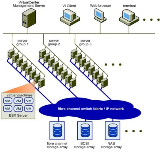
As an outstanding software solution for x86 virtualization, VMware enables users to manage their virtual environments in an effective and easy manner. Figure 1-1 shows the VMware Infrastructure virtual data center that consists of x86 computing servers, storage networks, storage arrays, IP networks, management servers, and desktop clients.
Issue (2014-02-10) Huawei Proprietary and Confidential Copyright © Huawei Technologies Co., Ltd..
2 Figure 1-1 VMware Infrastructure virtual data center
Figure 1-2 provides an example of storage architecture in VMware Infrastructure. A Virtual Machine File System (VMFS) volume contains one or more LUNs belonging to different storage arrays. Multiple ESX servers share one VMFS volume and create virtual disks on the VMFS volume for VMs.
Issue (2014-02-10) Huawei Proprietary and Confidential Copyright © Huawei Technologies Co., Ltd..
3 Figure 1-2 Storage architecture in VMware Infrastructure
VMware uses VMFS to centrally manage storage systems. VMFS is a shared cluster file system designed for VMs. This file system employs the distributed lock function to enable independent access to disks, ensuring that a VM is accessed by one physical host at a time. Raw Device Mapping (RDM) acts as the agent for raw devices on a VMFS volume.
1.2 File Systems in VMware
VMware VMFS is a high-performance cluster file system that allows multiple systems to concurrently access the shared storage, laying a solid foundation for the management of VMware clusters and dynamic resources.
Features of VMFS
Automated maintenance directory structure File lock mechanism
Distributed logical volume management Dynamic capacity expansion
Cluster file system Journal logging
Issue (2014-02-10) Huawei Proprietary and Confidential Copyright © Huawei Technologies Co., Ltd..
4
Advantages of VMFS
Improved storage utilization Simplified storage management
ESX server clusters of enhanced performance and reliability
Architecture of VMFS
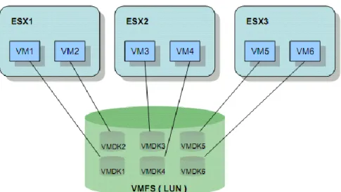
In the VMFS architecture shown in Figure 1-3, a LUN is formatted into a VMFS file system, whose storage space is shared by three ESX servers each carrying two VMs. Each VM has a Virtual Machine Disk (VMDK) file that is stored in a directory (named after a VM) automatically generated by VMFS. VMFS adds a lock for each VMDK to prevent a VMDK from being accessed by two VMs at the same time.
Figure 1-3 VMFS architecture
Structure of a VMFS Volume
Figure 1-4 shows the structure of a VMFS volume. A VMFS volume consists of one or more partitions that are arranged in lines. Only after the first partition is used out can the following partitions be used. The identity information about the VMFS volume is recorded in the first partition.
Issue (2014-02-10) Huawei Proprietary and Confidential Copyright © Huawei Technologies Co., Ltd..
5 Figure 1-4 Structure of a VMFS volume
VMFS divides each extent into multiple blocks, each of which is then divided into smaller blocks. This block-based management is typically suitable for VMs. Files stored on VMs can be categorized as large files (such as VMDK files, snapshots, and memory swap files) and small files (such as log files, configuration files, and VM BIOS files). Large and small blocks are allocated to large and small files respectively. In this way, storage space is effectively utilized and the number of fragments in the file system is minimized, improving the storage performance of VMs.
The VMFS-3 file system supports four data block sizes: 1 MB, 2 MB, 4 MB, and 8 MB. Sizes of files and volumes supported by VMFS-3 file systems vary with a file system's block size.
1.3 VMware RDM
VMware RDM enables VMs to directly access storage. As shown in Figure 1-5, an RDM disk exists as an address mapping file on the VMFS volume. This mapping file can be considered as a symbolic link that maps a VM's access to an RDM disk to LUNs.
Issue (2014-02-10) Huawei Proprietary and Confidential Copyright © Huawei Technologies Co., Ltd..
6 Figure 1-5 RDM mechanism
RDM provides two compatible modes, both of which supports vMotion, Distributed Resource Scheduler (DRS), and High Availability (HA).
Virtual compatibility: fully simulates VMDK files and supports snapshots.
Physical compatibility: directly accesses SCSI devices and does not support snapshots. RDMs are applicable in the following scenarios:
Physical to Virtual (P2V): migrates services from a physical machine to a virtual machine.
Virtual to Physical (V2P): migrates services from a virtual machine to a physical machine.
Clustering physical machines and virtual machines.
1.4 VMware Cluster
VMware Cluster consists of a group of ESX servers that jointly manage VMs, dynamically assign hardware resources, and automatically allocate VMs. With VMware Cluster, loads on VMs can be dynamically transferred among ESX hosts. VMware Cluster is the foundation for Fault Tolerance (FT), High Availability (HA), and Distributed Resource Scheduler (DRS).
1.5 VMware vMotion
VMware vMotion can migrate running VMs to facilitate the maintenance of physical machines. VMs can be automatically migrated within a VMware cluster. Free VM migration balances loads among physical machines, improving application performance. VMware vMotion has demanding requirements on the CPU compatibility of physical hosts. VMs can only be migrated among physical machines that run CPUs of the same series.
1.6 VMware DRS
VMware DRS constantly monitors the usage of resource pools in a VMware cluster, and intelligently allocates resources to VMs based on service requirements. Deploying VMs onto
Issue (2014-02-10) Huawei Proprietary and Confidential Copyright © Huawei Technologies Co., Ltd..
7 a small number of physical machines may result in unexpected resource bottlenecks.
Resources required by VMs may exceed those available on physical machines. VMware DRS offers an automated mechanism to constantly balance capacities and migrate VMs onto physical machines with sufficient resources. As a result, each VM can invoke resources in a timely manner regardless of locations.
1.7 VMware FT and VMware HA
VMware FT and VMware HA provide effective failover for physical hardware and VM operating systems. VMware FT and VMware HA can:
Monitor VM status to detect faults on physical hardware and operating systems. Restart VMs on another physical machine automatically when the current physical
machine where the VMs reside becomes faulty.
Restart VMs to protect applications upon operating system faults.
1.8 Specifications
VMware specifications vary with VMware versions. Table 1-1 lists major VMware specifications.
Table 1-1 Major specifications of VMware
Category Specifications Max. Value
4.0 4.1 5.0 5.1 5.5
iSCSI Physical
LUNs per Server 2561 256 256 256 256
Paths to a LUN 8 8 8 8 8
Number of total paths on a server
1024 1024 1024 1024 1024
Fibre Channel LUNs per host 2561 256 256 256 256
LUN size 512 B to 2 TB 512 B to 2 TB --- 64 TB 64 TB LUN ID 255 255 255 255 255 Number of paths to a LUN 16 32 32 32 32
Number of total paths on a server 1024 1024 1024 1024 1024 Number of HBAs of any type 8 8 8 8 8 HBA ports 16 16 16 16 16
Issue (2014-02-10) Huawei Proprietary and Confidential Copyright © Huawei Technologies Co., Ltd..
8
FCoE Software FCoE
adapters
--- --- 4 4 4
NAS NFS mounts per host --- 64 256 256 256
NFS Default NFS datastores 8 --- --- --- --- NFS datastores 64 (requir es change s to advanc ed settings ) --- --- --- ---
VMFS Raw device mapping
(RDM) size 512 B to 2 TB 512 B to 2 TB --- --- --- Volume Size 16 KB to 64 to TB 64 TB --- --- 64 TB
Volume Per host 256 256 256 256 256
VMFS-2 Files per volume 256 +
(64 x additio nal extents ) --- --- --- --- Block size 256 MB --- --- --- --- VMFS-3 VMFS-3 volumes
configured per host
256 --- --- --- ---
Files per volume ~30,72 02 ~30,72 02 ~30,72 02 ~30,72 02 ~30,72 02 Block size 8 MB 8 MB 8 MB 8 MB 8 MB Volume Size --- --- 64 TB3 64 TB3 --- VMFS-5 Volume Size --- --- 64 TB4 64 TB4 ---
Files per volume --- --- ~13069
0 ~13069 0 ~13069 0
1. Local disks are included.
2. The file quantity is sufficient to support the maximum number of VMs.
Issue (2014-02-10) Huawei Proprietary and Confidential Copyright © Huawei Technologies Co., Ltd..
9 4. The volume size is also subject to RAID controllers or adapter drivers.
The table lists only part of specifications. For more information, see: VMware vSphere Configuration Maximums (4.0)
VMware vSphere Configuration Maximums (4.1) VMware vSphere Configuration Maximums (5.0) VMware vSphere Configuration Maximums (5.1) VMware vSphere Configuration Maximums (5.5)
Issue (2014-02-10) Huawei Proprietary and Confidential Copyright © Huawei Technologies Co., Ltd..
10
2
Network Planning
VMware hosts and storage systems can be networked based on different criteria. Table 2-1 describes the typical networking modes.
Table 2-1 Networking modes
Criteria Networking Mode
Interface module type Fibre Channel network/iSCSI network Whether switches are
used
Direct-connection network (no switches are used)/Switch-based network (switches are used)
Whether multiple paths exist
Single-path network/Multi-path network
The Fibre Channel network is the most widely used network for VMware operating systems. To ensure service data security, both direct-connection network and switch-based network are multi-path networks.
The following details commonly used Fibre Channel and iSCSI networks.
2.1 Fibre Channel Network Diagram
2.1.1 Multi-Path Direct-Connection Network
Huawei provides dual-controller and multi-controller storage systems, whose network diagrams differ. The following describes network diagrams of dual-controller and multi-controller storage systems respectively.
Dual-Controller
The following uses HUAWEI OceanStor S5500T as an example to explain how to connect a VMware host to a storage system over a Fibre Channel multi-path direct-connection network, as shown in Figure 2-2.
Issue (2014-02-10) Huawei Proprietary and Confidential Copyright © Huawei Technologies Co., Ltd..
11 Figure 2-1 Fibre Channel multi-path direct-connection network diagram (dual-controller)
On this network, both controllers of the storage system are connected to the host's HBAs through optical fibers.
Multi-Controller
The following uses HUAWEI OceanStor 18800 (four-controller) as an example to explain how to connect a VMware host to a storage system over a Fibre Channel multi-path direct-connection network, as shown in Figure 2-2.
Figure 2-2 Fibre Channel multi-path direct-connection network diagram (four-controller)
On this network, the four controllers of the storage system are connected to the host's HBAs through optical fibers.
2.1.2 Multi-Path Switch-based Network
Huawei provides dual-controller and multi-controller storage systems, whose network diagrams differ. The following describes network diagrams of dual-controller and multi-controller storage systems respectively.
Dual-Controller
The following uses HUAWEI OceanStor S5500T as an example to explain how to connect a VMware host to a storage system over a Fibre Channel multi-path switch-based network, as shown in Figure 2-3.
Issue (2014-02-10) Huawei Proprietary and Confidential Copyright © Huawei Technologies Co., Ltd..
12 Figure 2-3 Fibre Channel multi-path switch-based network diagram (dual-controller)
On this network, the storage system is connected to the host via two switches. Both controllers of the storage system are connected to the switches through optical fibers and both switches are connected to the host through optical fibers. To ensure the connectivity between the host and the storage system, each zone contains only one storage port and its corresponding host port.
Multi-Controller
The following uses HUAWEI OceanStor 18800 (four-controller) as an example to explain how to connect a VMware host to a storage system over a Fibre Channel multi-path switch-based network, as shown in Figure 2-4.
Issue (2014-02-10) Huawei Proprietary and Confidential Copyright © Huawei Technologies Co., Ltd..
13
On this network, the storage system is connected to the host via two switches. All controllers of the storage system are connected to the switches through optical fibers and both switches are connected to the host through optical fibers. To ensure the connectivity between the host and the storage system, each zone contains only one storage port and its corresponding host port.
2.2 iSCSI Network Diagram
2.2.1 Multi-Path Direct-Connection Network
Huawei provides dual-controller and multi-controller storage systems, whose network diagrams differ. The following describes network diagrams of dual-controller and multi-controller storage systems respectively.
Dual-Controller
The following uses HUAWEI OceanStor S5500T as an example to explain how to connect a VMware host to a storage system over an iSCSI multi-path direct-connection network, as shown in Figure 2-5.
Figure 2-5 iSCSI multi-path direct-connection network diagram (dual-controller)
On this network, both controllers of the storage system are connected to the host's network adapter through Ethernet cables.
Multi-Controller
The following uses HUAWEI OceanStor 18800 (four-controller) as an example to explain how to connect a VMware host to a storage system over an iSCSI multi-path
Issue (2014-02-10) Huawei Proprietary and Confidential Copyright © Huawei Technologies Co., Ltd..
14 Figure 2-6 iSCSI multi-path direct-connection network diagram (four-controller)
On this network, the four controllers of the storage system are connected to the host's network adapter through Ethernet cables.
2.2.2 Multi-Path Switch-based Network
Huawei provides dual-controller and multi-controller storage systems, whose network diagrams differ. The following describes network diagrams of dual-controller and multi-controller storage systems respectively.
Dual-Controller
The following uses HUAWEI OceanStor S5500T as an example to explain how to connect a VMware host to a storage system over an iSCSI multi-path switch-based network, as shown in Figure 2-7.
Issue (2014-02-10) Huawei Proprietary and Confidential Copyright © Huawei Technologies Co., Ltd..
15
On this network, the storage system is connected to the host via two Ethernet switches. Both controllers of the storage system are connected to the switches through Ethernet cables and both switches are connected to the host's network adapter through Ethernet cables. To ensure the connectivity between the host and the storage system, each VLAN contains only one storage port and its corresponding host port.
Multi-Controller
The following uses HUAWEI OceanStor 18800 (four-controller) as an example to explain how to connect a VMware host to a storage system over an iSCSI multi-path switch-based network, as shown in Figure 2-8.
Figure 2-8 iSCSI multi-path switch-based network diagram (four-controller)
On this network, the storage system is connected to the host via two Ethernet switches. All controllers of the storage system are connected to the switches through Ethernet cables and both switches are
connected to the host's network adapter through Ethernet cables. To ensure the connectivity between the host and the storage system, each VLAN contains only one storage port and its corresponding host port.
Issue (2014-02-10) Huawei Proprietary and Confidential Copyright © Huawei Technologies Co., Ltd..
16
3
Preparations Before Configuration (on a
Host)
Before connecting a host to a storage system, make sure that the host HBAs are ide ntified and working correctly. You also need to obtain the WWNs of HBA ports. The WWNs will be used in subsequent configuration on the storage system.
This chapter details how to check the HBA status and query WWNs of HBA ports.
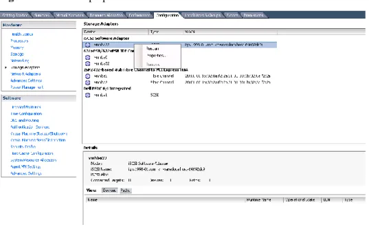
3.1 HBA Identification
After an HBA is installed on a host, view information about the HBA on the host. Go to the page for configuration management and choose Storage Adapters in the navigation tree. In the function pane, hardware devices on the host are displayed, as shown in Figure 3-1. Figure 3-1 Viewing the HBA information
Issue (2014-02-10) Huawei Proprietary and Confidential Copyright © Huawei Technologies Co., Ltd..
17
3.2 HBA Information
After a host identifies a newly installed HBA, you can view properties of the HBA on the host.
The method of querying HBA information varies with operating system versions. The following details how to query HBA information on ESXi 5.5 and versions earlier than ESXi 5.5.
3.2.1 Versions Earlier than ESXi 5.5
The command for viewing the HBA properties varies according to the HBA type. The details are as follows:
QLogic HBA
The command syntax is as follows:
cat /proc/scsi/qla2xxx/N
The following is an example:
~ # cat /proc/scsi/qla2xxx/4
QLogic PCI to Fibre Channel Host Adapter for QMI2572:
FC Firmware version 5.03.15 (d5), Driver version 901.k1.1-14vmw
Host Device Name vmhba1 BIOS version 2.09 FCODE version 3.14 EFI version 2.27
Flash FW version 5.03.09 ISP: ISP2532
Request Queue = 0x7810000, Response Queue = 0x7851000 Request Queue count = 2048, Response Queue count = 512 Number of response queues for multi-queue operation: 0 Total number of interrupts = 11346570
Device queue depth = 0x40
Number of free request entries = 675 Total number of outstanding commands: 0 Number of mailbox timeouts = 0
Number of ISP aborts = 0 Number of loop resyncs = 1
Host adapter:Loop State = <READY>, flags = 0x1a268 Link speed = <4 Gbps>
Dpc flags = 0x0
Link down Timeout = 030 Port down retry = 005 Login retry count = 008 Execution throttle = 2048 ZIO mode = 0x6, ZIO timer = 1
Commands retried with dropped frame(s) = 0 Product ID = 4953 5020 2532 0002
NPIV Supported : Yes Max Virtual Ports = 254 SCSI Device Information:
scsi-qla0-adapter-node=20000024ff32f612:010300:0;
Issue (2014-02-10) Huawei Proprietary and Confidential Copyright © Huawei Technologies Co., Ltd..
18
FC Target-Port List:
scsi-qla0-target-0=20090022a10bc8ee:010f00:81:Online;
The previous output provides information such as the HBA driver version, topology, WWN, and negotiated rate.
Emulex HBA
The command syntax is as follows:
cat /proc/scsi/lpfcxxx/N
The following is an example:
~ # cat /proc/scsi/lpfc820/8
Emulex LightPulse FC SCSI 8.2.2.1-18vmw
IBM 42D0494 8Gb 2-Port PCIe FC HBA for System x on PCI bus 0000:81 device 01 irq 65 port 1
BoardNum: 1
ESX Adapter: vmhba4
Firmware Version: 1.11A5 (US1.11A5)
Portname: 10:00:00:00:c9:d4:82:83 Nodename: 20:00:00:00:c9:d4:82:83 SLI Rev: 3
MQ: Unavailable
NPIV Supported: VPIs max 255 VPIs used 1
RPIs max 4096 RPIs used 9 IOCBs inuse 0 IOCB max 8 txq cnt 0 txq max 0 txcmplq 0
Vport List:
ESX Adapter: vmhba37
Vport DID 0x30101, vpi 1, state 0x20
Portname: 20:aa:00:0c:29:00:07:1a Nodename: 20:aa:00:0c:29:00:06:1a Link Up - Ready:
PortID 0x30100 Fabric
Current speed 8G
Port Discovered Nodes: Count 1
t0000 DID 030500 WWPN 20:0a:30:30:37:30:30:37 WWNN 21:00:30:30:37:30:30:37 qdepth 8192 max 31 active 1 busy 0
~ #
The previous output provides information such as HBA model and driver.
Brocade HBA
cat /proc/scsi/bfaxxx/N
3.2.2 ESXi 5.5
Since ESXi 5.5, the /proc/scsi/ directory contains no content. Run the following commands to query HBA information:
Issue (2014-02-10) Huawei Proprietary and Confidential Copyright © Huawei Technologies Co., Ltd..
19
~ # esxcli storage core adapter list
HBA Name Driver Link State UID Description --- --- --- ---
---
vmhba0 ahci link-n/a sata.vmhba0 (0:0:31.2) Intel Corporation Patsburg 6 Port SATA AHCI Controller
vmhba1 megaraid_sas link-n/a unknown.vmhba1 (0:3:0.0) LSI / Symbios Logic MegaRAID SAS Fusion Controller
vmhba2 rste link-n/a pscsi.vmhba2 (0:4:0.0) Intel Corporation Patsburg 4-Port SATA Storage Control Unit
vmhba3 qlnativefc link-up fc.50014380062d222d:50014380062d222c (0:129:0.0) QLogic Corp ISP2532-based 8Gb Fibre Channel to PCI Express HBA
vmhba4 qlnativefc link-up fc.50014380062d222f:50014380062d222e (0:129:0.1) QLogic Corp ISP2532-based 8Gb Fibre Channel to PCI Express HBA
vmhba32 ahci link-n/a sata.vmhba32 (0:0:31.2) Intel Corporation Patsburg 6 Port SATA AHCI Controller
vmhba33 ahci link-n/a sata.vmhba33 (0:0:31.2) Intel Corporation Patsburg 6 Port SATA AHCI Controller
vmhba34 ahci link-n/a sata.vmhba34 (0:0:31.2) Intel Corporation Patsburg 6 Port SATA AHCI Controller
vmhba35 ahci link-n/a sata.vmhba35 (0:0:31.2) Intel Corporation Patsburg 6 Port SATA AHCI Controller
vmhba36 ahci link-n/a sata.vmhba36 (0:0:31.2) Intel Corporation Patsburg 6 Port SATA AHCI Controller
~ # ~ #
~ # esxcfg-module -i qlnativefc
esxcfg-module module information
input file: /usr/lib/vmware/vmkmod/qlnativefc License: GPLv2 Version: 1.0.12.0-1vmw.550.0.0.1331820 Name-space: Required name-spaces: com.vmware.vmkapi@v2_2_0_0 Parameters: ql2xallocfwdump: int
Option to enable allocation of memory for a firmware dump during HBA initialization. Memory allocation requirements vary by ISP type. Default is 1 - allocate memory. ql2xattemptdumponpanic: int
Attempt fw dump for each function on PSOD Default is 0 - Don't attempt fw dump. ql2xbypass_log_throttle: int
Option to bypass log throttling.Default is 0 - Throttling enabled. 1 - Log all errors. ql2xcmdtimeout: int
Timeout value in seconds for scsi command, default is 20 ql2xcmdtimermin: int
Minimum command timeout value. Default is 30 seconds. ql2xdevdiscgoldfw: int
Option to enable device discovery with golden firmware Default is 0 - no discovery. 1 - discover device.
ql2xdisablenpiv: int
Option to disable/enable NPIV feature globally. 1 - NPIV disabled. Default is 0 - NPIV enabled.
ql2xenablemsi2422: int
Enables MSI interrupt scheme on 2422sDefault is 0 - disable MSI-X/MSI. 1 - enable MSI-X/MSI.
Issue (2014-02-10) Huawei Proprietary and Confidential Copyright © Huawei Technologies Co., Ltd..
20
ql2xenablemsi24xx: int
Enables MSIx/MSI interrupt scheme on 24xx cardsDefault is 1 - enable MSI-X/MSI. 0 - disable MSI-X/MSI.
ql2xenablemsix: int
Set to enable MSI or MSI-X interrupt mechanism. 0 = enable traditional pin-based interrupt mechanism. 1 = enable MSI-X interrupt mechanism (Default). 2 = enable MSI interrupt mechanism.
ql2xexecution_throttle: int
IOCB exchange count for HBA.Default is 0, set intended value to override Firmware defaults.
ql2xextended_error_logging: int
Option to enable extended error logging, Default is 0 - no logging. 1 - log errors. ql2xfdmienable: int
Enables FDMI registratons Default is 1 - perfom FDMI. 0 - no FDMI. ql2xfwloadbin: int
Option to specify location from which to load ISP firmware: 2 -- load firmware via the request_firmware() (hotplug) interface. 1 -- load firmware from flash. 0 -- use default semantics.
ql2xiidmaenable: int
Enables iIDMA settings Default is 1 - perform iIDMA. 0 - no iIDMA. ql2xintrdelaytimer: int
ZIO: Waiting time for Firmware before it generates an interrupt to the host to notify completion of request.
ql2xioctltimeout: int
IOCTL timeout value in seconds for pass-thur commands. Default is 66 seconds. ql2xioctltimertest: int
IOCTL timer test enable - set to enable ioctlcommand timeout value to trigger before fw cmdtimeout value. Default is disabled
ql2xloginretrycount: int
Specify an alternate value for the NVRAM login retry count. ql2xlogintimeout: int
Login timeout value in seconds. ql2xmaxlun: int
Defines the maximum LUNs to register with the SCSI midlayer. Default is 256. Maximum allowed is 65535.
ql2xmaxqdepth: int
Maximum queue depth to report for target devices. ql2xmaxsgs: int
Maximum scatter/gather entries per request,Default is the Max the OS Supports. ql2xmqcpuaffinity: int
Enables CPU affinity settings for the driver Default is 0 for no affinity of request and response IO. Set it to 1 to turn on the cpu affinity.
ql2xmqqos: int
Enables MQ settings Default is 1. Set it to enable queues in MQ QoS mode. ql2xoperationmode: int
Option to disable ZIO mode for ISP24XX: Default is 1, set 0 to disable ql2xplogiabsentdevice: int
Option to enable PLOGI to devices that are not present after a Fabric scan. This is needed for several broken switches. Default is 0 - no PLOGI. 1 - perfom PLOGI. ql2xqfullrampup: int
Number of seconds to wait to begin to ramp-up the queue depth for a device after a queue-full condition has been detected. Default is 120 seconds.
Issue (2014-02-10) Huawei Proprietary and Confidential Copyright © Huawei Technologies Co., Ltd..
21
Controls whether the driver tracks queue full status returns and dynamically adjusts a scsi device's queue depth. Default is 1, perform tracking. Set to 0 to disable dynamic tracking and adjustment of queue depth.
ql2xusedefmaxrdreq: int
Default is 0 - adjust PCIe Maximum Read Request Size. 1 - use system default. qlport_down_retry: int
Maximum number of command retries to a port that returns a PORT-DOWN status. ~ #
The previous output provides information such as HBA model, WWN, and driver. You can run the following command to obtain more HBA details:
# /usr/lib/vmware/vmkmgmt_keyval/vmkmgmt_keyval -a
Listing all system keys:
Key Value Instance: QLNATIVEFC/qlogic
Listing keys: Name: 0 Type: string value:
QLogic PCI to Fibre Channel Host Adapter for HPAJ764A:
FC Firmware version 5.09.00 (90d5), Driver version 1.0.12.0
Host Device Name vmhba3 BIOS version 2.12 FCODE version 2.03 EFI version 2.05
Flash FW version 4.04.04
ISP: ISP2532, Serial# MY5001219T MSI-X enabled
Request Queue = 0x41094e3b6000, Response Queue = 0x41094e3d7000 Request Queue count = 2048, Response Queue count = 512
Number of response queues for multi-queue operation: 2 CPU Affinity mode enabled
Total number of MSI-X interrupts on vector 0 (handler = ff40) = 371 Total number of MSI-X interrupts on vector 1 (handler = ff41) = 29 Total number of MSI-X interrupts on vector 2 (handler = ff42) = 2173 Total number of MSI-X interrupts on vector 3 (handler = ff43) = 6916 Device queue depth = 0x40
Number of free request entries = 238 Total number of outstanding commands: 0 Number of mailbox timeouts = 0
Number of ISP aborts = 0 Number of loop resyncs = 14
Host adapter:Loop State = [DEAD], flags = 0x205a260 Link speed = [Unknown]
Dpc flags = 0x0
Link down Timeout = 008 Port down retry = 010 Login retry count = 010 Execution throttle = 2048 ZIO mode = 0x6, ZIO timer = 1
Issue (2014-02-10) Huawei Proprietary and Confidential Copyright © Huawei Technologies Co., Ltd..
22
Product ID = 4953 5020 2532 0002
NPIV Supported : Yes Max Virtual Ports = 254
Number of Virtual Ports in Use = 1 SCSI Device Information:
scsi-qla0-adapter-node=50014380062d222d:000000:0; scsi-qla0-adapter-port=50014380062d222c:000000:0; FC Target-Port List:
scsi-qla0-target-0=200a303037303037:030900:1000:[Offline]; scsi-qla0-target-1=200b303037303037:030900:0:[Offline]; Virtual Port Information:
Virtual Port WWNN:WWPN:ID =2636000c29000128:2636000c29000328:000000; Virtual Port 1:VP State = [FAILED], Vp Flags = 0x0
Virtual Port 1:Request-Q ID = [2] FC Port Information for Virtual Port 1:
scsi-qla3-port-0=2100303037303037:200a303037303037:030900:1000; scsi-qla3-port-1=2100303037303037:200b303037303037:030900:0; Name: 1
Type: string value:
QLogic PCI to Fibre Channel Host Adapter for HPAJ764A:
FC Firmware version 5.09.00 (90d5), Driver version 1.0.12.0 Host Device Name vmhba4
BIOS version 2.12 FCODE version 2.03 EFI version 2.05
Flash FW version 4.04.04
ISP: ISP2532, Serial# MY5001219T MSI-X enabled
Request Queue = 0x41094e42b000, Response Queue = 0x41094e44c000 Request Queue count = 2048, Response Queue count = 512
Number of response queues for multi-queue operation: 2 CPU Affinity mode enabled
Total number of MSI-X interrupts on vector 0 (handler = ff44) = 384 Total number of MSI-X interrupts on vector 1 (handler = ff45) = 39 Total number of MSI-X interrupts on vector 2 (handler = ff46) = 144185 Total number of MSI-X interrupts on vector 3 (handler = ff47) = 11278 Device queue depth = 0x40
Number of free request entries = 546 Total number of outstanding commands: 0 Number of mailbox timeouts = 0
Number of ISP aborts = 0 Number of loop resyncs = 14
Host adapter:Loop State = [DEAD], flags = 0x204a260 Link speed = [Unknown]
Dpc flags = 0x0
Issue (2014-02-10) Huawei Proprietary and Confidential Copyright © Huawei Technologies Co., Ltd..
23
Port down retry = 010 Login retry count = 010 Execution throttle = 2048 ZIO mode = 0x6, ZIO timer = 1
Commands retried with dropped frame(s) = 0 Product ID = 4953 5020 2532 0002
NPIV Supported : Yes Max Virtual Ports = 254
Number of Virtual Ports in Use = 1 SCSI Device Information:
scsi-qla1-adapter-node=50014380062d222f:000000:0; scsi-qla1-adapter-port=50014380062d222e:000000:0; FC Target-Port List:
scsi-qla1-target-0=2018303037303037:030a00:1000:[Offline]; scsi-qla1-target-1=2019303037303037:030a00:0:[Offline]; Virtual Port Information:
Virtual Port WWNN:WWPN:ID =2636000c29000128:2636000c29000228:000000; Virtual Port 1:VP State = [FAILED], Vp Flags = 0x0
Virtual Port 1:Request-Q ID = [2] FC Port Information for Virtual Port 1:
scsi-qla2-port-0=2100303037303037:2018303037303037:030a00:1000; scsi-qla2-port-1=2100303037303037:2019303037303037:030a00:0; Name: 2
Type: string
value: Instance not found on this system. ……
Name: 15 Type: string
value: Instance not found on this system. Name: DRIVERINFO Type: string value: Driver version 1.0.12.0 Module Parameters ql2xlogintimeout = 20 qlport_down_retry = 10 ql2xplogiabsentdevice = 0 ql2xloginretrycount = 0 ql2xallocfwdump = 1 ql2xioctltimeout = 66 ql2xioctltimertest = 0 ql2xextended_error_logging = 0 ql2xdevdiscgoldfw = 0 ql2xattemptdumponpanic= 0 ql2xfdmienable = 1
Issue (2014-02-10) Huawei Proprietary and Confidential Copyright © Huawei Technologies Co., Ltd..
24 ql2xmaxqdepth = 64 ql2xqfulltracking = 1 ql2xqfullrampup = 120 ql2xiidmaenable = 1 ql2xusedefmaxrdreq = 0 ql2xenablemsix = 1 ql2xenablemsi24xx = 1 ql2xenablemsi2422 = 0 ql2xoperationmode = 1 ql2xintrdelaytimer = 1 ql2xcmdtimeout = 20 ql2xexecution_throttle = 0 ql2xmaxsgs = 0 ql2xmaxlun = 256 ql2xmqqos = 1 ql2xmqcpuaffinity = 1 ql2xfwloadbin = 0 ql2xbypass_log_throttle = 0 ~ # ~ #
The previous output provides more detailed HBA information. For more information, visit:
http://kb.vmware.com/selfservice/microsites/search.do?language=en_US&cmd=displayKC&e xternalId=1031534
For details about how to modify the HBA queue depth, visit:
http://kb.vmware.com/selfservice/microsites/search.do?language=en_US&cmd=displayKC&e xternalId=1267
Issue (2014-02-10) Huawei Proprietary and Confidential Copyright © Huawei Technologies Co., Ltd..
25
4
Preparations Before Configuration (on a
Storage System)
Make sure that RAID groups, LUNs, and hosts are correctly created on the storage systems. These configurations are common and therefore not detailed here.
Issue (2014-02-10) Huawei Proprietary and Confidential Copyright © Huawei Technologies Co., Ltd..
26
5
Configuring Switches
VMware hosts and storage systems can be connected over a Fibre Channel switch-based network and an iSCSI switch-based network. A Fibre Channel switch-based network uses Fibre Channel switches and an iSCSI network uses Ethernet switches. This chapter describes how to configure a Fibre Channel switch and an Ethernet switch respectively.
5.1 Fibre Channel Switch
The commonly used Fibre Channel switches are mainly from Brocade, Cisco, and QLogic. The following uses a Brocade switch as an example to explain how to configure switches.
5.1.1 Querying the Switch Model and Version
Perform the following steps to query the switch model and version:
Step 1 Log in to the Brocade switch from a web page.
On the web page, enter the IP address of the Brocade switch. The Web Tools switch login dialog box is displayed. Enter the account and password. The default account and password are admin and password. The switch management page is displayed.
CAUTION
Web Tools works correctly only when Java is installed on the host. Java 1.6 or later is recommended.
Step 2 View the switch information.
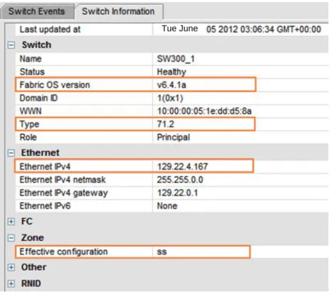
On the switch management page that is displayed, click Switch Information. The switch information is displayed, as shown in Figure 5-1.
Issue (2014-02-10) Huawei Proprietary and Confidential Copyright © Huawei Technologies Co., Ltd..
27 Figure 5-1 Switch information
Tue June
Note the following parameters:
Fabric OS version: indicates the switch version information. The interoperability between switches and storage systems varies with the switch version. Only switches of authenticated versions can interconnect correctly with storage systems.
Type: This parameter is a decimal consists of an integer and a decimal fraction. The integer indicates the switch model and the decimal fraction indicates the switch template version. You only need to pay attention to the switch model. Table 5-1Table 5-1
describes switch model mapping.
Table 5-1 Mapping between switch types and names
Switch
Type Switch Name Switch Type Switch Name
1 Brocade 1000 Switch 58 Brocade 5000 Switch
2,6 Brocade 2800 Switch 61 Brocade 4424 Embedded
Switch
3 Brocade 2100, 2400 Switches 62 Brocade DCX Backbone
4 Brocade 20x0, 2010, 2040, 2050 Switches 64 Brocade 5300 Switch 5 Brocade 22x0, 2210, 2240, 2250 Switches 66 Brocade 5100 Switch
Issue (2014-02-10) Huawei Proprietary and Confidential Copyright © Huawei Technologies Co., Ltd..
28
Switch Type
Switch Name Switch
Type
Switch Name
9 Brocade 3800 Switch 69 Brocade 5410 Blade
10 Brocade 12000 Director 70 Brocade 5410 Embedded
Switch
12 Brocade 3900 Switch 71 Brocade 300 Switch
16 Brocade 3200 Switch 72 Brocade 5480 Embedded
Switch
17 Brocade 3800VL 73 Brocade 5470 Embedded
Switch
18 Brocade 3000 Switch 75 Brocade M5424 Embedded
Switch
21 Brocade 24000 Director 76 Brocade 8000 Switch
22 Brocade 3016 Switch 77 Brocade DCX-4S
Backbone
26 Brocade 3850 Switch 83 Brocade 7800 Extension
Switch
27 Brocade 3250 Switch 86 Brocade 5450 Embedded
Switch
29 Brocade 4012 Embedded
Switch
87 Brocade 5460 Embedded
Switch
32 Brocade 4100 Switch 90 Brocade 8470 Embedded
Switch
33 Brocade 3014 Switch 92 Brocade VA-40FC Switch
34 Brocade 200E Switch 95 Brocade VDX
6720-24 Data Center Switch 37 Brocade 4020 Embedded Switch 96 Brocade VDX 6730-32 Data Center Switch
38 Brocade 7420 SAN Router 97 Brocade VDX
6720-60 Data Center Switch
40 Fibre Channel Routing (FCR) Front Domain
98 Brocade VDX
6730-76 Data Center Switch
41 Fibre Channel Routing, (FCR) Xlate Domain
108 Dell M8428-k FCoE
Embedded Switch
Issue (2014-02-10) Huawei Proprietary and Confidential Copyright © Huawei Technologies Co., Ltd..
29
Switch Type
Switch Name Switch
Type Switch Name 43 Brocade 4024 Embedded Switch 116 Brocade VDX 6710 Data Center Switch
44 Brocade 4900 Switch 117 Brocade 6547 Embedded
Switch
45 Brocade 4016 Embedded
Switch
118 Brocade 6505 Switch
46 Brocade 7500 Switch 120 Brocade DCX 8510-8
Backbone 51 Brocade 4018 Embedded Switch 121 Brocade DCX 8510-4 Backbone 55.2 Brocade 7600 Switch
Ethernet IPv4: indicates the switch IP address.
Effective Configuration: indicates the currently effective configurations. This parameter is important and is related to zone configurations. In this example, the currently effective configuration is ss.
----End
5.1.2 Configuring Zones
Zone configuration is important for Fibre Channel switches. Perform the following steps to configure switch zones:
Step 1 Log in to the Brocade switch from a web page. This step is the same as that in section 5.1.1
"Querying the Switch Model and Version."
Step 2 Check the switch port status.
Normally, the switch port indicators are steady green, as shown in Figure 5-2. Figure 5-2 Switch port indicator status
If the port indicators are abnormal, check the topology mode and rate. Proceed with the next step after all indicators are normal.
Step 3 Go to the Zone Admin page.
In the navigation tree of Web Tools, choose Task > Manage > Zone Admin. You can also choose Manage > Zone Admin in the navigation bar.
Issue (2014-02-10) Huawei Proprietary and Confidential Copyright © Huawei Technologies Co., Ltd..
30
Step 4 Check whether the switch identifies hosts and storage systems.
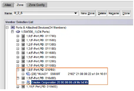
On the Zone Admin page, click the Zone tab. In Ports&Attached Devices, check whether all related ports are identified, as shown in Figure 5-3.
Figure 5-3 Zone tab page
The preceding figure shows that ports 1,8 and 1,9 in use are correctly identified by the switch.
Step 5 Create a zone.
On the Zone tab page, click New Zone to create a new zone and name it zone_8_9. Select ports 1,8 and 1,9 and click Add Member to add them to the new zone, as shown in Figure 5-4.
Issue (2014-02-10) Huawei Proprietary and Confidential Copyright © Huawei Technologies Co., Ltd..
31
CAUTION
To ensure data is transferred separately, ensure that each zone contains one initiator and one target only.
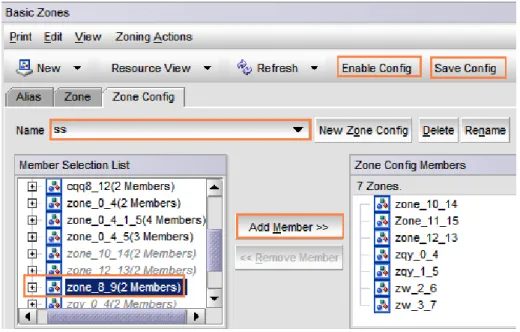
Step 6 Add the new zone to the configuration file and activate the new zone.
On the Zone Admin page, click the Zone Config tab. In the Name drop-down list, choose the currently effective configuration ss.
In Member Selection List, select zone zone_8_9 and click Add Member to add it to the configuration file.
Click Save Config to save the configuration and click Enable Config to make the configuration effective.
Figure 5-5 shows the Zone Config page. Figure 5-5 Zone Config tab page
Step 7 Verify that the configuration takes effect.
In the navigation tree of Web Tools, choose Task > Monitor > Name Server to go to the Name Server page. You can also choose Monitor > Name Server in the navigation bar. Figure 5-6 shows the Name Server page.
Issue (2014-02-10) Huawei Proprietary and Confidential Copyright © Huawei Technologies Co., Ltd..
32 Figure 5-6 Name Server page
The preceding figure shows that ports 8 and 9 are members of zone_8_9 that is now effective. An effective zone is marked by an asterisk (*).
----End
5.1.3 Precautions
Note the following when connecting a Brocade switch to a storage system at a rate of 8 Gbit/s:
The topology mode of the storage system must be set to switch.
fill word of ports through which the switch is connected to the storage system must be set to 0. To configure this parameter, run the portcfgfillword <port number> 0 command on the switch.
Note the following when connecting a Brocade switch to a storage system at a rate of 8 Gbit/s:
When the switch is connected to module HP VC 8Gb 20-port FC or HP VC FlexFabric 10Gb/24-port, change the switch configuration. For details, visit:
https://h20566.www2.hp.com/portal/site/hpsc/template.PAGE/public/psi/troubleshootDis play/?javax.portlet.prp_efb5c0793523e51970c8fa22b053ce01=wsrp-navigationalState% 3DdocId%3Demr_na-c02619780%7CdocLocale%3Dzh_CN&lang=en&javax.portlet.be gCacheTok=com.vignette.cachetoken&sp4ts.oid=3984629&javax.portlet.endCacheTok= com.vignette.cachetoken&javax.portlet.tpst=efb5c0793523e51970c8fa22b053ce01&hpa ppid=sp4ts&cc=US&ac.admitted=1337927146324.876444892.199480143
5.2 Ethernet Switch
This section describes how to configure Ethernet switches, including configuring VLANs and binding ports.
Issue (2014-02-10) Huawei Proprietary and Confidential Copyright © Huawei Technologies Co., Ltd..
33
5.2.1 Configuring VLANs
On an Ethernet network to which many hosts are connected, a large number of broadcast packets are generated during the host communication. Broadcast packets sent from one
host will be received by all other hosts on the network, consuming more bandwidth. Moreover, all hosts on the network can access each other, resulting data security risks.
To save bandwidth and prevent security risks, hosts on an Ethernet network are divided into multiple logical groups. Each logical group is a VLAN. The following uses HUAWEI Quidway 2700 Ethernet switch as an example to explain how to configure VLANs. In the following example, two VLANs (VLAN 1000 and VLAN 2000) are created. VLAN 1000 contains ports GE 1/0/1 to 1/0/16. VLAN 2000 contains ports GE 1/0/20 to 1/0/24.
Step 1 Go to the system view.
<Quidway>system-view
System View: return to User View with Ctrl+Z.
Step 2 Create VLAN 1000 and add ports to it.
[Quidway]VLAN 1000
[Quidway-vlan1000]port GigabitEthernet 1/0/1 to GigabitEthernet 1/0/16
Step 3 Configure the IP address of VLAN 1000.
[Quidway-vlan1000]interface VLAN 1000
[Quidway-Vlan-interface1000]ip address 1.0.0.1 255.255.255.0
Step 4 Create VLAN 2000, add ports, and configure the IP address.
[Quidway]VLAN 2000
[Quidway-vlan2000]port GigabitEthernet 1/0/20 to GigabitEthernet 1/0/24
[Quidway-vlan2000]interface VLAN 2000
[Quidway-Vlan-interface2000]ip address 2.0.0.1 255.255.255.0
----End
5.2.2 Binding Ports
When storage systems and hosts are connected in point-to-point mode, existing bandwidth may be insufficient for storage data transmission. Moreover, devices cannot be redundantly connected in point-to-point mode. To address these problems, ports are bound (link
aggregation). Port binding can improve bandwidth and balance load among multiple links.
Link Aggregation Modes
Three Ethernet link aggregation modes are available: Manual aggregation
Manually run a command to add ports to an aggregation group. Ports added to the aggregation group must have the same link type.
Static aggregation
Manually run a command to add ports to an aggregation group. Ports added to the aggregation group must have the same link type and LACP enabled.
Issue (2014-02-10) Huawei Proprietary and Confidential Copyright © Huawei Technologies Co., Ltd..
34 The protocol dynamically adds ports to an aggregation group. Ports added in this way must have LACP enabled and the same speed, duplex mode, and link type.
Table 5-2 compares the three link aggregation modes. Table 5-2 Comparison of link aggregation modes
Link Aggregation
Mode Packet Exchange Port Detection CPU Usage
Manual aggregation No No Low
Static aggregation Yes Yes High
Dynamic aggregation
Yes Yes High
Configuration
HUAWEI OceanStor storage devices support 802.3ad link aggregation (dynamic aggregation). In this link aggregation mode, multiple network ports are in an active aggregation group and work in duplex mode and at the same speed. After binding iSCSI host ports on a storage device, enable aggregation for their peer ports on a switch. Otherwise, links are unavailable between the storage device and the switch.
This section uses switch ports GE 1/0/1 and GE 1/0/2 and iSCSI host ports P2 and P3 as examples to explain how to bind ports. You can adjust related parameters based on site requirements.
Bind the iSCSI host ports.
Step 2 Log in to the ISM and go to the page for binding ports.
In the ISM navigation tree, choose Device Info > Storage Unit > Ports. In the function pane, click iSCSI Host Ports.
Step 3 Bind ports.
Select the ports that you want to bind and choose Bind Ports > Bind in the menu bar. In this example, the ports to be bound are P2 and P3.
The Bind iSCSI Port dialog box is displayed. In Bond name, enter the name for the port bond and click OK.
The Warning dialog box is displayed. In the Warning dialog box, select I have read the warning message carefully and click OK.
The Information dialog box is displayed, indicating that the operation succeeded. Click OK. After the storage system ports are bound, configure link aggregation on the switch. Run the following command on the switch:
<Quidway>system-view
System View: return to User View with Ctrl+Z. [Quidway-Switch]interface GigabitEthernet 1/0/1
[Quidway-Switch-GigabitEthernet1/0/19]lacp enable
LACP is already enabled on the port! [Quidway-Switch-GigabitEthernet1/0/19]quit
Issue (2014-02-10) Huawei Proprietary and Confidential Copyright © Huawei Technologies Co., Ltd..
35
[Quidway-Switch]interface GigabitEthernet 1/0/2
[Quidway-Switch-GigabitEthernet1/0/20]lacp enable
LACP is already enabled on the port! [Quidway-Switch-GigabitEthernet1/0/20]quit
After the command is executed, LACP is enabled for ports GE 1/0/1 and GE 1/0/2. Then the ports can be automatically detected and added to an aggregation group.
Issue (2014-02-10) Huawei Proprietary and Confidential Copyright © Huawei Technologies Co., Ltd..
36
6
Establishing Fibre Channel Connections
After connecting a host to a storage system, check the topology modes of the host and the storage system. Fibre Channel connections are established between the host and the storage system after host initiators are identified by the storage system. The following describes how to check topology modes and add initiators.
6.1 Checking Topology Modes
On direct-connection networks, HBAs support specific topology modes. The topology mode of a storage system must be consistent with that of supported by host HBAs.
You can use the ISM to manually change the topology mode of a storage system to that supported by host HBAs. If the storage ports connected to host HBAs are adaptive, there is no need to manually change the storage system topology mode.
The method for checking topology modes varies with storage systems. The following describes how to check the topology mode of the OceanStor T series storage system and the OceanStor 18000 series enterprise storage system.
6.1.1 OceanStor T Series Storage System
The check method is as follows:In the ISM navigation tree, choose Device Info > Storage Unit > Ports. In the function pane, click FC Host Ports. Select a port connected to the host and then view the port details, Figure 6-1 shows the details about a Fibre Channel port.
Issue (2014-02-10) Huawei Proprietary and Confidential Copyright © Huawei Technologies Co., Ltd..
37 Figure 6-1 Fibre Channel port details
As shown in the preceding figure, the topology mode of the OceanStor T series storage system is Public Loop.
6.1.2 OceanStor 18000 Series Enterprise Storage System
In the ISM navigation tree, choose System. Then click the device view iconin the upper right corner. Choose Controller Enclosure ENG0 > Controller > Interface Module > FC Port and click the port whose details that you want to view, as shown in Figure 6-2.
In the navigation tree, you can see controller A and controller B, each of which has different interface modules. Choose a controller and an interface module based on actual conditions.
Figure 6-2 Fibre Channel port details
As shown in the preceding figure, the port working mode of the OceanStor 18000 storage system is P2P.
Issue (2014-02-10) Huawei Proprietary and Confidential Copyright © Huawei Technologies Co., Ltd..
38
6.2 Adding Initiators
This section describes how to add host HBA initiators on a storage system. Perform the following steps to add initiators:
Step 1 Check HBA WWNs on the host.
Step 2 Check host WWNs on the storage system and add the identified WWNs to the host.
The method for checking host WWNs varies with storage systems. The following describes how to check WWNs on the OceanStor T series storage system and the OceanStor 18000 storage system.
OceanStor T series storage system (V100 and V200R001)
Log in to the ISM and choose SAN Services > Mappings > Initiators in the navigation tree. In the function pane, check the initiator information. Ensure that the WWNs in step 1 are identified. If the WWNs are not identified, check the Fibre Channel port status. Ensure that the port status is normal.
OceanStor 18000 Series Enterprise Storage System
Log in to the ISM and choose Host in the navigation tree. On the Initiator tab page, click Add Initiator and check that the WWNs in step 1 are found. If the WWNs are not identified, check the Fibre Channel port status. Ensure that the port status is normal. ----End
6.3 Establishing Connections
Add the WWNs (initiators) to the host and ensure that the initiator connection status is Online.
If the initiator status is Online, Fibre Channel connections are established correctly. If the initiator status is Offline, check the physical links and topology mode.
Issue (2014-02-10) Huawei Proprietary and Confidential Copyright © Huawei Technologies Co., Ltd..
39
7
Establishing iSCSI Connections
Both a host and a storage system need to be configured before establishing iSCSI connections between the host and the storage system. This chapter describes how to configure a host and a storage system before establishing iSCSI connections.
7.1 Host Configurations
7.1.1 Configuring Service IP Addresses
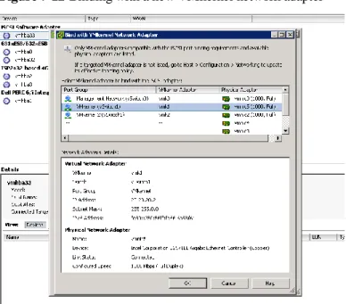
You can configure services IP addresses on a VMware host by adding virtual networks. Perform the following steps:
Step 1 In vSphere Client, choose Network > Add Network.
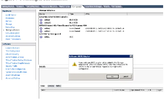
Step 2 In Add Network Wizard that is displayed, select VMkernel, as shown in Figure 7-1.
Figure 7-1 Adding VMkernel
Click Next.
Issue (2014-02-10) Huawei Proprietary and Confidential Copyright © Huawei Technologies Co., Ltd..
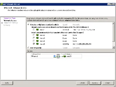
40 Figure 7-2 Creating a vSphere standard switch
Step 4 Specify the network label, as shown in Figure 7-3.
Figure 7-3 Specifying the network label
Issue (2014-02-10) Huawei Proprietary and Confidential Copyright © Huawei Technologies Co., Ltd..
41 Figure 7-4 Entering the iSCSI service IP address
Step 6 Confirm the information that you have configured, as shown in Figure 7-5.
Figure 7-5 Information summary
For a single-path network, the configuration is completed. For a multi-path network, proceed with the next step.
Step 7 Repeat steps 1 to 6 to create another virtual network.