METRx
™
System
Surgical Technique
METRx X-TUBE
Retraction System
MEDTRONIC SOFAMOR DANEK USA, INC.
1800 Pyramid Place Memphis, TN 38132
(901) 396-3133 (800) 876-3133
Customer Service: (800) 933-2635
www.sofamordanek.com
LITMTXST420 01
19 97
1996
2000
the Micro Endoscopic
Discectomy (MED)
system became the
fi rst reliable mechanism for
minimally invasive access to the
posterior lumbar spine. As surgical
applications for this technology
expanded, the MED system evolved
into the Minimal Exposure Tubular
Retractor (METRx) system. This
tubular retractor technology has
been awarded several US Patents
and achieved excellent clinical
results as evident in its numerous
clinical publications. The following
timeline helps illustrate how METRx
helped pioneer the minimally
invasive surgical approach.
1st Microendoscopic
Patent Filed
1st clinical case with
Micro Endoscopic
Discectomy (MED)
System
1st cervical
foraminotomy
performed with
MED system
1st patent for
Minimally Invasive
Interbody Fusion
fi led
6,152,871
6,162,170
29724233.4
PATENTS6,176,823
6,206,822
6,217,509
PATENTS2002
20 01
19 97
1998
2003
1999
Microendoscopic Discectomy authored by KEVIN T. FOLEY, MD MAURICE M. SMITH, MD Semmes-Murphy Clinic Department of Neurosurgery University of Tennessee Memphis, Tennessee Microendoscopic Approach To Far-Lateral Lumbar Disc Herniation authored by KEVIN T. FOLEY, MD MAURICE M. SMITH, MD Semmes-Murphy Clinic Department of Neurosurgery University of Tennessee Memphis, Tennessee Y. RAJA RAMPERSAUD, MD Department of Neurosurgery University of Toronto Toronto, Ontario, CanadaBilateral Decompressive Surgery In Lumbar Spinal Stenosis Associated With
Spondylolisthesis: Unilateral Approach
And Use Of A Microscope And Tubular
Retractor System authored by
SYLVAIN PALMER, MD ROBERT TURNER, MD ROSEMARY PALMER, RN
Mission Hospital Regional Medical Center, Mission Viejo, California
A Minimally Invasive Technique For Decompression
Of The Lumbar Spine authored by BERNARD H. GUIOT, MD, FRCS(C) Department of Neurosurgery University of Florida Gainesville, Flordida LARRY T. KHOO, MD RICHARD G. FESSLER, MD, PHD
Institute for Spine Care Chicago Institute of Neurosurgery & Neuroresearch
Chicago, Illinois Microendoscopic Posterior Cervical Laminoforaminotomy For Unilateral Radiculopathy: Results Of A New Technique In 100 Cases authored by TIM E. ADAMSON, MD Carolina Neurosurgery and Spine Associates Charlotte, North Carolina
Microdiscectomy With Minimally Invasive
Tubular Retractor authored by
DONALD LONG HILTON, JR., MD
Northeast Baptist Hospital, San Antonio, Texas
1st publish for
far lateral approach
with METRx
1st Microendoscopic
Discectomy patent
issued
1st patent for
Minimally Invasive
Interbody Fusion
issued
5,902,231
5,954,635
6,007,487
PATENTS6,425,859
PATENTS6,520,907
6,679,833
2004
PATENTS ARTICLE ARTICLE ARTICLE ARTICLE ARTICLE ARTICLE ARTICLE Minimally Invasive Transforaminal Lumbar Interbody Fusion (TLIF): Technical Feasibility AndInitial Results.
authored by JAMES D. SCHWENDER, MD
Twin Cities Spine Center & Department of Orthopedic Surgery,
University of Minnesota, Minneapolis, Minnesota LANGSTON T. HOLLY, MD
Division of Neurosurgery, UCLA Medical Center, Los Angeles, California DAVID P. ROUBEN, MD River City Orthopaedic Surgeons,
Louisville, Kentucky KEVIN T. FOLEY, MD Semmes-Murphey Clinic & Department of Neurosurgery
University of Tennessee Memphis, Tennessee
The spinal needle is removed and a vertical incision is made
at the puncture site. The incision length should match the
diameter of the respective tubular retractor – 14mm tubular
retractor, 14mm incision, and so on.
Some practitioners also incise the fascia to make tissue
dilation easier. This is optional and can be performed later
if tissue dilation is difficult.
The guidewire is placed through the incision and directed
toward the appropriate anatomy under lateral fluoroscopy.
The guidewire is advanced only through the lumbodorsal
fascia. Great care must be taken
to avoid penetration of the
ligamentum flavum and
inadvertent dural puncture
with possible nerve injury
or spinal fluid leak.
Targeting Using the METRx
™System
Guidewire Insertion
Procedure
Landmark Docking Point
Discectomy,
Laminectomy, Stenosis
Inferior Aspect of the
Superior Lamina
PLIF
Medial Aspect of the Facet
Pedicle Screws
Transverse Process/
Facet Junction
TLIF
Lateral Aspect of the Facet
Cervical Foraminotomy
Medial Facet/Laminar Junction
Far Lateral
Junction of TP and PARS of
Superior Vertebra
A METRx System procedure is initiated by inserting a
spinal needle into the paraspinal musculature at the
appropriate distance off the midline toward the bony
anatomy. The placement is confirmed using lateral fluoroscopy.
Insert the cannulated soft tissue dilator over the guidewire
utilizing a twisting motion. Once the fascia is penetrated,
remove the guidewire and advance the dilator down to the
bony anatomy.
Use the initial dilator to palpate the anatomy in both the
coronal and sagittal planes. This maneuver confirms an
appropriate approach laterally and helps expedite soft
tissue removal.
First Dilator Insertion
Sequential Dilation and
Tubular Retractor Insertion
Repositioning the Tubular Retractor
If repositioning of the tubular retractor is necessary, the
retractor can be moved or angled over the pathology by
a process known as wanding. Insert the matching color
dilator into the tube. While downward pressure is
placed on the tubular retractor, the flexible arm is
unlocked, allowing the tubular retractor to be pivoted
over the desired location.
The next series of dilators are sequentially placed over
each other. Only use the number of dilators required to
get to the preferred tubular retractor diameter. The depth
markings on the dilators are noted to indicate the tubular
retractor length appropriate to the patient’s anatomy.
The optimum tubular retractor is placed over the
sequential dilators and seated firmly on the bony
anatomy. The flexible arm is attached to the bed rail and
the selected tubular retractor.
The flexible arm is secured and the sequential dilators
are removed, establishing a tubular operative corridor.
40˚
and 90˚ Bayoneted Kerrison
(1mm, 2mm, 3mm, 4mm, 5mm Available)
The MIDAS REX
®LEGEND
™High Speed Drill (TT12C curved attachment)
2mm Straight and Upbiting Micropituitary
2mm Pituitary with Tooth Curved Scissors (Standard and Microsizes Available)
4mm Straight and Upbiting Pituitary
2mm Upbiting and Downbiting Pituitary
Sheathed Annulatomy Knife Blade (Disposable)
Bayoneted Annulatomy Knife (Disposable)
Suction Retractor
Nerve Hooks – Straight, Left, and Right (Standard and Microsizes Available)
Wide Nerve Root Retractor
Bayoneted Bipolar Forceps (Standard and Microsizes Available)
Angled Bipolar Forceps (Standard and Microsizes Available)
Nerve Root Retractor
90° Ball Probes Long and Short, Left, Right, and Straight
90° Dissectors Left, Right, and Straight
Reverse Angled Curettes 1.8mm, 3.6mm, and 5.2mm
Bayoneted Bovie (Disposable)
Assorted Bayoneted Instruments
Sucker (#6, #8, #10, and
Suction Retractor Available)
Angled Curettes 1.8mm, 3.6mm, and 5.2mm
Straight Curettes 1.8mm, 3.6mm, and 5.2mm
45° Woodson Probe
Penfield Push and Pull (#2 and #4 Sizes Available)
Flex arm with self-retaining retractors
X-TUBE™ Retraction 4cm to 8cm Length 26mm Diameter
(Stainless and Disposable Available) 12.8mm Dilator 3cm to 9cm Length 14mm Diameter 14.8mm Dilator 3cm to 9cm Length 16mm Diameter 16.8mm Dilator 3cm to 9cm Length 18mm Diameter
(Stainless and Disposable Available)
18.8mm Dilator 3cm to 9cm Length 20mm Diameter 20.8mm Dilator 3cm to 9cm Length 22mm Diameter
(Stainless and Disposable Available)
22.8mm Dilator
24.8mm Dilator
3cm to 9cm Length 26mm Diameter
(Stainless and Disposable Available)
.062 x 12”
Guidewire 5.3mm Dilator 9.4mm Dilator
24.8mm Dilator Flex arm
Cer
vical F
or
aminotom
y
Tec
hnical Guide
METRx
™
System
Cervical Foraminotomy Technical Guide
M
ET
Rx
™Sy
ste
m
Patient Positioning
and Room Set-up
METRx posterior cervical foraminal access is performed in a similar stepwise fashion as described in the previous posterior lumbar steps with the following exceptions:
Anatomic location – cervical spine Patient position – the patient is placed in a Mayfield pin holder with frame extended as far as possible to allow adequate AP fluoroscopic visualization. The fluoroscope is rotated so the line of view is perpendicular to the spinal laminar line. Generally the fluoroscope will come in from the surgeons right, the surgeon being seated directly at the patient’s head (Figure 1) when the tubular retractor is safely docked in operating position the fluoroscope can be moved to allow the
microscope to be brought in.
Guidewire Insertion – A 20-gauge spinal needle is inserted into the paraspinous musculature approximately 1 cm to 2 cm off midline at the appropriate level. The AP fluoro will allow the surgeon to safely access the lateral mass and stay clear of the canal. A stab wound is made over the needle puncture site and the localizing guidewire is passed down below the fascia. The guidewire is advanced through the deep cervical fascia (Figure 2). It is not necessary to purchase the guidewire on the bone of the lateral mass. If this is done extreme care should be taken to make certain the guidewire is safely docked well lateral on the lateral mass.
Dilator Insertion – Posterior cervical soft tissue is slightly more dense and requires more care to be taken as dilators are rotated incrementally down to the lateral mass until the desired tubular retractor is in place (Figure 3).
Figure 1
Figure 2
©2004 Medtronic Sofamor Danek USA, Inc. All Rights Reserved.
MEDTRONIC SOFAMOR DANEK USA, INC.
1800 Pyramid Place, Memphis, TN 38132
(901) 396-3133 (800) 876-3133
Customer Service: (800) 933-2635
www.sofamordanek.com
Soft Tissue Removal and
Lamina Identification
The soft tissue over the lamina and intralaminar space is removed with an extended Bovie on low power and pituitary rongeurs (Figure 4). If the tube is correctly positioned the junction of the two lamina with the medial facet should be seen in the tube (Figure 5). The initial laminar bites are taken in the caudal lamina in a caudal then lateral and then cranial direction as the cranial laminar edge is addressed last (Figure 6). The bony work should continue until each pedicle is exposed.
Cervical Root Identification
and Disc Removal
With bipedal exposure the axilla is generally explored first. Frequently a soft disc will be completely removed through the axilla.
Occasionally more cranially located fragments will have to be removed through the shoulder. The cervical penfield and hook can be used to gently retract the root in the axilla (Figure 7). The disc will frequently be seen in this location. The bayonetted knife may be used to incise the ligament as needed. The longer hook may be used to explore the foramen after removal of the disc. Cotton patties may be used to obtain hemostasis along with microbipolar forceps.
Closure
After the root is decompressed this site is irrigated thoroughly with saline. The flexible arm should then be loosened and the retractor slowly removed incrementally. Bleeding should be progressively controlled with bipolar coagulation as the retractor is withdrawn.
It is generally impossible to close the fascia. Subcuticular closures are done in an inverted manner and Steri-Strips or a Band-Aid may then be uses as desire. Dermabond is also frequently used.
Figure 4
Figure 6
Figure 7
Figure 1
Figure 2
Figure 3
Figure 4
See METRx Brochure for steps that precede this technique (Part# LITMTXST4)
METRx
™
System
Discectomy Technical Guide
M
ET
Rx
™Sy
ste
m
Soft Tissue Removal and
Laminar Identification
It is essential to remove all soft tissue exposed in the operative corridor in order to maximize the working space within the tubular retractor. This can be accomplished with a pituitary rongeur and/or electorcautery.
The laminar edge is identified and the ligmentum flavum is detached from the undersurface of the lamina with a small angled curette (Figure 1).
Laminar and Interlaminar
Space Identification
A hemilaminotomy/medial facetotomy is then performed with a Kerrison punch or high speed drill (Figure 2). Lateral recess and/or foraminal stenosis can be addressed in this fashion. Effective utilization of lateral fluoroscopy will help tailor the dissection as necessary to access specific pathology. When the decompression is done mainly for lumbar stenosis and not a disc herniation, the laminotomy is carried just cephalad to the insertion of the ligamentum flavum onto the underside of the lamina. This assures that all hypertrophied ligamentum will be removed, adequately decompressing the canal. If the pathology is beyond the confines of the tubular retractor, wanding can be used to reposition the tubular retractor.
Ligamentum Flavum
Removal
The ligament is penetrated with the curette or ball probe utilizing a twisting motion under the remaining superior lamina where the ligament is thin (Figure 3). It is peeled back caudally and dorsally, then resected with a Kerrison punch (Figure 4).
Discectom
y
Tec
©2004 Medtronic Sofamor Danek USA, Inc. All Rights Reserved.
Figure 5
Figure 6
Figure 7
MEDTRONIC SOFAMOR DANEK USA, INC.
1800 Pyramid Place, Memphis, TN 38132
(901) 396-3133 (800) 876-3133
Customer Service: (800) 933-2635
www.sofamordanek.com
Nerve Root Exploration
and Retraction
There is an initial tendency to “cone” the exposure down to the final target reducing the working space and visualization in the tubular retractor. In order to avoid this, it is important to complete soft tissue, bone and ligament removal over the entire area of the exposure. Figure 5 shows appropriate exposure of the epidural space.
The dura and traversing nerve root are identified. The nerve root is retracted medially utilizing a penfield dissector, Love style or suction retractor (Figure 5). The volar epidural space can then be explored. If necessary, epidural veins can be cauterized with bipolar forceps and divided with micro scissors (Figure 6). Cotton patties can also be used to obtain hemostasis.
Discectomy and Closure
Identify the disc herniation. If an annulotomy is necessary, it can be accomplished with the annulotomy knife while protecting the nerve root with the retractor. The herniated disc is then removed with a pituitary rongeur in a standard fashion (Figure 7). Intradiscal and extradiscal work can be carried out as one would normally perform during an open microdiscectomy. The nerve root is explored to ensure thedecompression is complete.
Once the nerve root is decompressed, irrigate the disc space thoroughly. Epidural steroids may be injected if desired. Loosen the flexible arm assembly and slowly remove the tubular retractor. Any bleeding in the paraspinal musculature can be controlled with the bipolar as the tube is removed.
METRx
™
System
Lumbar Stenosis Technical Guide
M
ET
Rx
™Sy
ste
m
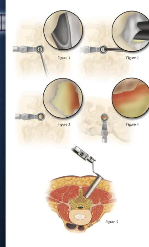
Decompression
In preparation for a spinal stenosis
procedure, insert the appropriate-sized
METRx System tube as described in
the METRx System Surgical Technique.
Once the tube is positioned, it is
important to extend the laminotomy
cephalad above the insertion of
the ligamentum flavum. This is to
insure resection of all hypertrophied
ligamentum. After the cephalad border
of the ligamentum is exposed it can be
separated from the dura using angled
curettes or a right or left ball tip dissector
(Figure 1). The ligamentum is then
resected with a 90° or 40° Kerrison
punch (Figure 2). To insure complete
decompression of the lateral recess,
the lateral exposure should allow
palpation of the inferior pedicle. This
often requires resection of the superior
border of the lower lamina (Figure 3).
It will also remove any caudal residual
ligamentum, which often can compress
the dura or nerve root. Foraminotomies
are then performed, as necessary, to
decompress both exposed foramina
(Figure 4). The ball tip probe should
be able to pass freely into both the
cephalad and caudal foramina.
After achieving the ipsilateral
decompression, a separate contralateral
exposure may be utilized to decompress
the opposite lateral recess by following
the aforesaid procedural steps (Figure 5).
Lumbar Stenosis
Tec
hnical Guide
Figure 1 Figure 2 Figure 3 Figure 4 Figure 5©2004 Medtronic Sofamor Danek USA, Inc. All Rights Reserved.
MEDTRONIC SOFAMOR DANEK USA, INC.
1800 Pyramid Place, Memphis, TN 38132
(901) 396-3133 (800) 876-3133
Customer Service: (800) 933-2635
www.sofamordanek.com
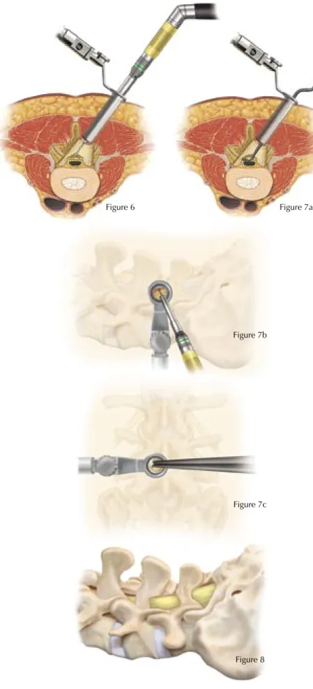
Contralateral Decompression
from an Ipsilateral Approach
As an alternative to contralateral
decompression from the contralateral
side, an ipsilateral approach to
contralateral decompression can be
utilized. After completion of the
ipsilateral decompression the tubular
retractor is angled medially to expose
the anterior spinous process. A drill can
then be utilized to resect the anterior
spinous process and the medial aspect
of the contralateral lamina (Figure 6).
This exposes the contralateral
hypertrophied ligamentum flavum,
which can then be resected using
Kerrison punches and curettes (Figures
7a, 7b and 7c). Care is taken to palpate
the caudal pedicle and probe both the
cephalad and caudal foramina to be
certain that the decompression is
complete (Figure 8).
Figure 6 Figure 7a
Figure 7b
Figure 7c
METRx
™
System
PLIF Technical Guide
M
ET
Rx
™Sy
ste
m
Preoperative Planning
The patient is placed on the operating table in the prone position with lateral C-arm fluoroscopy. Care should be used to maintain the patient in a lumbar lordotic position.
Spinal needle is placed into paraspinous musculature 2 – 2.5cm off of midline at the appropriate level confirmed using lateral fluoroscopy.
The Guidewire is placed through the incision and directed toward the facet under lateral fluoroscopy.
Dilation/tubular retraction
Insert initial cannulated soft tissue Dilator over the Guidewire. Once the fascia is penetrated, remove the Guidewire and advance the Dilator over the facet. Confirm the placement of initial Dilator using lateral fluoroscopy.Laminotomy, Facetectomy,
& Discectomy
A conventional discectomy is performed by incising the annulus with a 15-scalpel blade lateral to the dural sac. This is done bilaterally and then soft fragments from the intradiscal space or extruded fragments are removed with Disc Rongeurs in a conventional fashion.
Disc space distraction
The disc space is sequentially distracted until original disc space height is obtained and normal foraminal opening is restored.
Insert the Distractor with the T-handle attached, with the flat surface parallel to the endplates.
Rotate the Distractor 90 degrees to distract the space and remove the T-handle.
Sequentially insert Distractors from side to side until the desired height is obtained.
The largest Distractor is left in the disc space in the distracted position while continued disc space preparation is performed.
PLIF
Tec
hnical Guide
See METRx Brochure for steps that precede this technique (Part# LITMTXST4)
Sequential Dilation and Tubular Retractor Insertion
©2004 Medtronic Sofamor Danek USA, Inc. All Rights Reserved.
MEDTRONIC SOFAMOR DANEK USA, INC.
1800 Pyramid Place, Memphis, TN 38132
(901) 396-3133 (800) 876-3133
Customer Service: (800) 933-2635
www.sofamordanek.com
Incorporates technology developed by Gary K. Michelson, M.D.
Disc space preparation
The smallest Rotate Cutter is inserted into the disc space with the cutting blades parallel to the dural sac.
The Rotate Cutter is rotated once or twice at a depth of 20mm to remove osteophytes at the dorsal endplate. Removing
osteophytes facilitates placement of the Cutting Chisel later in the procedure.
The Rotate Cutter is then inserted up to a depth of 30mm and rotated to remove residual intradiscal material.
Remaining soft tissue or cartilaginous endplate covering are removed with vigorous scraping or curettage.
Scrape medially under the midline and gradually work laterally in a sweeping motion until both caudal and cephalad endplates are cleared of soft tissue.
The removal of the soft tissue from the endplate surface allows optimal graft incorporation.
Endplate Preparation
With the dura protected or minimally retracted, the lateral extensions of the Cutting Chisel are seated into the disc space. Place the lateral edge of the Cutting Chisel on or lateral to the mid-sagittal line of the pedicle.
The Chisel is impacted into the disc space. The cutting blades will remove the residual osteophytes and create an optimal bed to receive the wedge.
To insert a 26mm graft, repeat the process and insert the Chisel to a depth of 35mm.
After impacting the Cutting Chisel up to a depth of 30mm, attach the Slap Hammer to the Chisel handle and rotate 90 degrees and remove the Chisel with a repeated gentle upward stroke.
Wedge Insertion
The appropriate size allograft wedge is firmly attached to the Inserter.
Gently impact the wedge down the previously prepared channel until it is 3 to 4mm below the posterior margin.
Once the wedge has been inserted on the contralateral side, the first Disc Distractor is removed. Morselized autograph acquired from local bony elements or the iliac crest is then packed into the prepared disc space beneath the midline structures.
The second Wedge is inserted into the disc space along the previously prepared track.
After the final wedge is placed, the extradural space and foramina are probed to ensure adequate decompression of the neural elements.
METRx
™
System
SCS Lead Implant Technical Guide
M
ET
Rx
™Sy
ste
m
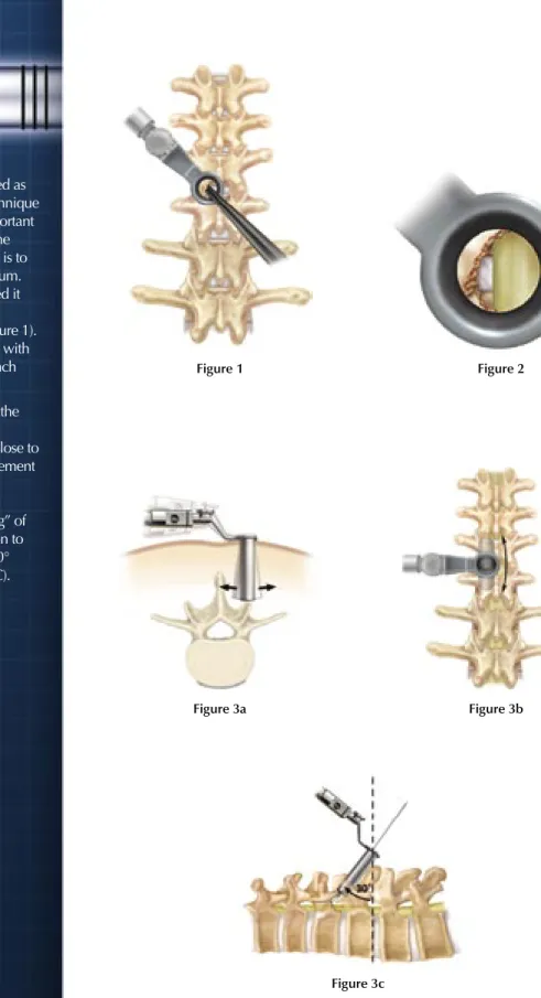
METRx Device Placement and
Spinal Preparation
To initiate spinal cord stimulator electrode placement, the METRx System tube is inserted as described in the METRx System Surgical Technique Guide. Once the tube is positioned, it is important to extend the laminotomy cephalad above the insertion of the ligamentum flavum (LF). This is to insure resection of all hypertrophied ligmentum. After the cephalad border of the LF is exposed it can be separated from the dura using angled curretts or a right or left ball tip dissector (Figure 1). A small hemi-laminotomy is then performed with use of various sized and angled Kerrison punch instruments and curretts (Figure 2).
The underlying LF is also resected to expose the dural surface. It is important that the medial border of the hemi-laminectomy extend as close to midline as possible in order to facilitate placement of the paddle lead. To allow for easier lead advancement and less dural compression, a paramedian oblique approach and “wanding” of the METRx tube to lessen the angle in relation to the spinal column can be employed up to 30° lateral and 30° caudal (Figure 3A, 3B and 3C).
SCS Lead Implant
Tec
hnical Guide
See METRx Brochure for steps that precede this technique (Part# LITMTXST4)
Figure 1 Figure 2
Figure 3a Figure 3b
©2004 Medtronic Sofamor Danek USA, Inc. All Rights Reserved.
MEDTRONIC SOFAMOR DANEK USA, INC.
1800 Pyramid Place, Memphis, TN 38132
(901) 396-3133 (800) 876-3133
Customer Service: (800) 933-2635
www.sofamordanek.com
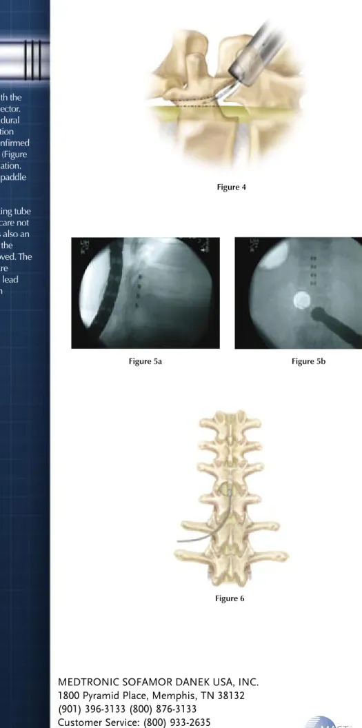
Lead Implantation
Clear any epidural scarring/adhesions with the epidural passing elevator or Penfield dissector. The paddle lead is then placed in the epidural space and advanced in a cephalad direction (Figure 4). The precise lead position is confirmed with fluoroscopy in AP and lateral views (Figure 5A and 5B) or through awake trial stimulation. After the lead is properly positioned, the paddle lead wires are secured to fascia or bone surrounding the adjacent facet with
nonabsorbable suture. The METRx working tube is then removed from the wound taking care not to dislodge the lead wires (Figure 6). It is also an option to anchor to the fascia overlaying the paraspinal muscles after the tube is removed. The fascia overlying the paraspinal muscles are reapproximated with suture. The paddle lead wires can then be tunneled to the chosen generator pocket area.
Figure 4
Figure 5a Figure 5b
METRx
™
System
TLIF Technical Guide
M
ET
Rx
™Sy
ste
m
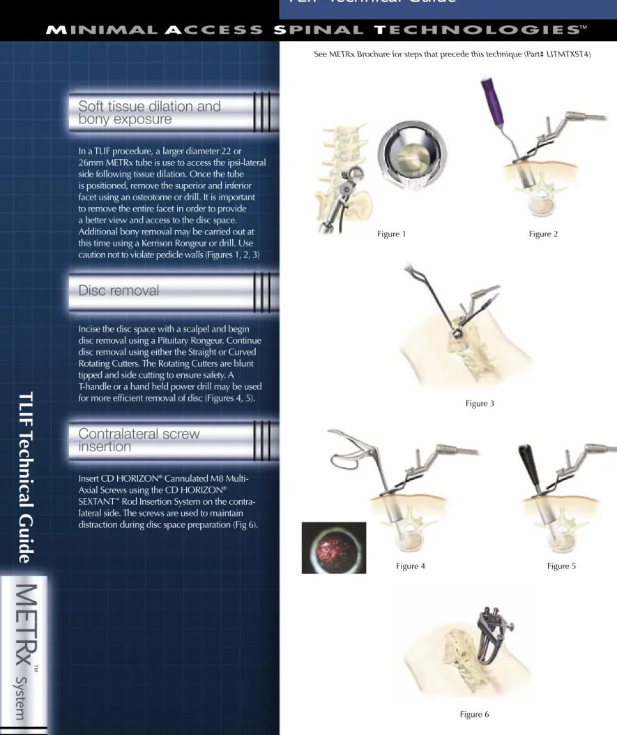
Soft tissue dilation and
bony exposure
In a TLIF procedure, a larger diameter 22 or 26mm METRx tube is use to access the ipsi-lateral side following tissue dilation. Once the tube is positioned, remove the superior and inferior facet using an osteotome or drill. It is important to remove the entire facet in order to provide a better view and access to the disc space. Additional bony removal may be carried out at this time using a Kerrison Rongeur or drill. Use caution not to violate pedicle walls (Figures 1, 2, 3)
Disc removal
Incise the disc space with a scalpel and begin disc removal using a Pituitary Rongeur. Continue disc removal using either the Straight or Curved Rotating Cutters. The Rotating Cutters are blunt tipped and side cutting to ensure safety. A T-handle or a hand held power drill may be used for more efficient removal of disc (Figures 4, 5).
Contralateral screw
insertion
Insert CD HORIZON® Cannulated M8
Multi-Axial Screws using the CD HORIZON®
SEXTANT™ Rod Insertion System on the
contra-lateral side. The screws are used to maintain distraction during disc space preparation (Fig 6).
TLIF
Tec
hnical Guide
See METRx Brochure for steps that precede this technique (Part# LITMTXST4)
Figure 1 Figure 2
Figure 3
Figure 4 Figure 5
©2004 Medtronic Sofamor Danek USA, Inc. All Rights Reserved.
MEDTRONIC SOFAMOR DANEK USA, INC.
1800 Pyramid Place, Memphis, TN 38132
(901) 396-3133 (800) 876-3133
Customer Service: (800) 933-2635
www.sofamordanek.com
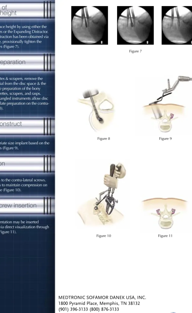
Restoration of
disc space height
Reestablish disc space height by using either the Impacted Distractors or the Expanding Distractor. Once adequate distraction has been obtained via the interbody space, provisionally tighten the contra-lateral screws (Figure 7).
Endplate preparation
Using various curettes & scrapers, remove the cartilaginous material from the disc space & the endplates. Continue preparation of the bony endplates using curettes, scrapers, and rasps. Specially designed angled instruments allow disc resection and endplate preparation on the contra-lateral side (Figure 8).
Interbody construct
insertion
Choose the appropriate size implant based on the use of the trial sizers (Figure 9).
Compression
Apply compression to the contra-lateral screws. Break-off set screws to maintain compression on the interbody device (Figure 10).
Ipsilateral screw insertion
Ipsi-lateral instrumentation may be inserted percutaneously or via direct visualization through
the METRx™ Tube (Figure 11).
Figure 7
Figure 8 Figure 9
M
ET
Rx
™Sy
ste
m
X-T
ube
Tec
hnical Guide
METRx
™
System
X-Tube Technical Guide
M
ET
Rx
™Sy
ste
m
XTube Introduction
A METRx
™X-Tube is selected in accordance
with exposed markings on the final dilator
(Figure 1). The X-Tube is then inserted over
the dilators and seated firmly flush with the
bony anatomy and locked in place with the
flexible arm. The dilators are then removed
establishing a tubular operative corridor.
XTube Deployment
X-TUBE is inserted over dilators and seated
firmly flush with bony anatomy and locked
in place with the flexible arm. Dilators are
removed establishing a tubular operative
corridor (Figure 2).
Figure 1Figure 2
©2004 Medtronic Sofamor Danek USA, Inc. All Rights Reserved.
MEDTRONIC SOFAMOR DANEK USA, INC.
1800 Pyramid Place, Memphis, TN 38132
(901) 396-3133 (800) 876-3133
Customer Service: (800) 933-2635
www.sofamordanek.com
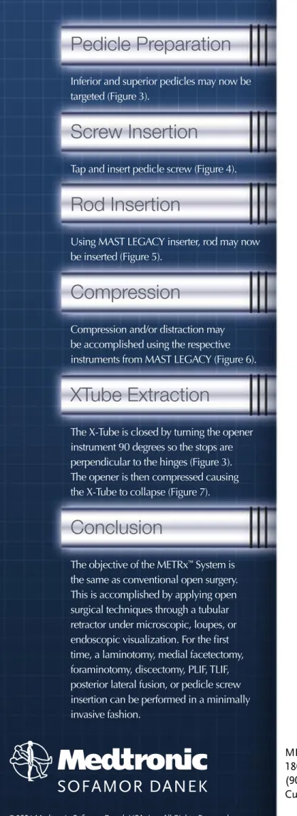
Pedicle Preparation
Inferior and superior pedicles may now be
targeted (Figure 3).
Screw Insertion
Tap and insert pedicle screw (Figure 4).
Rod Insertion
Using MAST LEGACY inserter, rod may now
be inserted (Figure 5).
Compression
Compression and/or distraction may
be accomplished using the respective
instruments from MAST LEGACY (Figure 6).
XTube Extraction
The X-Tube is closed by turning the opener
instrument 90 degrees so the stops are
perpendicular to the hinges (Figure 3).
The opener is then compressed causing
the X-Tube to collapse (Figure 7).
Conclusion
The objective of the METRx
™System is
the same as conventional open surgery.
This is accomplished by applying open
surgical techniques through a tubular
retractor under microscopic, loupes, or
endoscopic visualization. For the first
time, a laminotomy, medial facetectomy,
foraminotomy, discectomy, PLIF, TLIF,
posterior lateral fusion, or pedicle screw
insertion can be performed in a minimally
invasive fashion.
Figure 3 Figure 4
Figure 5 Figure 6
METRx Large Tube System
METRx X-TUBE
Retraction System
METRx Micro
Instrumentation
RADIANCE X
™Illumination
System
RADIANCE
™Illumination
System
18, 22, and 26mm
Disposable Tubes
Microdiscectomy and
MicroEndoscopic
Discectomy
Procedure Kits
©2004 Medtronic Sofamor Danek USA, Inc. All Rights Reserved.