Improving Security and Privacy in
Current Mobile Systems
Submitted by
Mohammed Shafiul Alam Khan
for the degree of Doctor of Philosophy
at
Royal Holloway, University of London
Declaration
I, Mohammed Shafiul Alam Khan, hereby declare that this thesis and the work pre-sented in it is entirely my own. Where I have consulted the work of others, this is always clearly stated.
Signed . . . (Mohammed Shafiul Alam Khan) Date:
Abstract
As has been widely discussed, the GSM system only offers unilateral authentication of the mobile phone to the network; this limitation permits a range of attacks. While adding support for mutual authentication would be highly beneficial, changing the way GSM serving networks operate is not practical.
The 3G and 4G mobile systems rectify the GSM weakness by providing mutual authentication between phone and network, and significantly improve their security properties by comparison with 2G (GSM). However, significant shortcomings remain with respect to user privacy, most notably the decades-old privacy problem of disclosure of the permanent subscriber identity (IMSI), a problem arising in all generations of mobile networks and that makes IMSI catchers a real threat. Although a number of possible modifications to 2G, 3G and 4G protocols have been proposed designed to provide greater user privacy, they all require significant alterations to the existing deployed infrastructures, which are almost certainly impractical in practice.
In this thesis we investigate whether it is possible to improve the security and privacy properties of the current mobile systems without changing the deployed infras-tructure, i.e. the serving networks and mobile phones.
We describe a novel modification to the relationship between a subscriber identity module (SIM) and its home network which allows mutual authentication without af-fecting the GSM infrastructure, including the phones; the only necessary changes are to the authentication centres and the SIMs.
We further propose novel authentication schemes for 3G and 4G systems to defeat IMSI catchers. Our first scheme makes use of multiple IMSIs for an individual USIM to offer a degree of pseudonymity for a user. The second scheme prevents disclosure of the subscriber’s IMSI by using a dynamic pseudo-IMSI that is only identifiable by the subscriber’s home network. A major challenge in using pseudonymous IMSIs is possible loss of identity synchronisation between a USIM and its home network, an issue that has not been adequately addressed in earlier work. We present an approach for identity recovery to be used in the event of pseudo-IMSI desynchronisation. Both schemes require changes to the home network and the USIM, both owned by a single entity in the mobile systems, but not to the serving network, mobile phone or other internal network protocols, enabling simple, transparent and evolutionary migration. We provide analyses of the schemes, and verify their correctness and security properties using ProVerif.
Acknowledgement
First and foremost, I would like to express my deepest gratitude to Professor Chris J Mitchell, my PhD supervisor and role model. I have greatly benefited from his guidance, kindness, patience, and cordial support. I wish to say a heartfelt thank you to him. Indeed, this thesis would never have become reality without his insightful ideas, invaluable comments and precious feedback.
I am extremely grateful to my mother, Mrs Jobeda Akhter Khanom, my brothers, Mr Nura Alam Khan and Mr Ashraful Alam Khan, my aunt, Mrs Shamsunnahar Khanom and all of my family members and friends for their endless support, continuous endorsement and enlightening advice; to them all I wish to say a sincere thank you.
I am profoundly appreciative to my colleagues, Mr Wanpeng Li, Mr Po-Wah Yau, Ms Mwawi Nyirenda Kayuni, Dr Zhang Xiao, Mrs Fatma Al Maqbali, Mr Nasser Al-Fannah, and Mr Zhaoyi Fan, for the friendly atmosphere they have created for our reading group and for the invaluable feedback and insightful ideas I got from them.
Thank you to all my friends within the Royal Holloway, University of London. Thanks to my friend, Mr Mohammed Marbin, for his generous support during my PhD study. I would also like to express my gratitude to my colleagues at Institute of Information Technology, University of Dhaka, Bangladesh for their supports and valuable advices.
I would like to thank my sponsor, Commonwealth Scholarship Commission in the United Kingdom, for financial support. I believe that it would not be possible to complete this study without their generous support.
I am particularly grateful to my wife and my lovely kids for their support during the stressful time of PhD research. Their presence makes me happy and helps me to concentrate in my work.
Finally, I own my sincere thanks to my mother for giving me the strength and motivation to do a PhD. I am thankful to almighty for being able to complete this thesis.
Contents
1 Introduction 1 1.1 Context of Research . . . 1 1.2 Motivation . . . 2 1.3 Contributions . . . 3 1.4 Publications . . . 5 1.5 Thesis Outline . . . 6 I Background 8 Overview 9 2 2G Mobile Systems 10 2.1 Introduction . . . 10 2.2 System Architecture . . . 10 2.2.1 Overview . . . 112.2.2 Security Context Classification . . . 13
2.3 System Identities . . . 14 2.3.1 IMSI . . . 14 2.3.2 IMEI . . . 15 2.3.3 MSISDN . . . 15 2.3.4 TMSI . . . 16 2.3.5 LAI . . . 16 2.4 Authentication Protocol . . . 16 2.5 Network Activities . . . 19 2.5.1 IMSI Attach . . . 19 2.5.2 Location Update . . . 20 2.5.3 Paging . . . 21
2.6 The SIM . . . 22
2.6.1 Memory Structure . . . 23
2.6.2 Application Protocol Data Units . . . 24
2.6.3 The SIM Application Toolkit . . . 25
2.7 General Packet Radio Service . . . 26
3 3G and 4G Mobile Systems 28 3.1 Introduction . . . 28 3.2 System Architecture . . . 28 3.2.1 3G Mobile Systems . . . 29 3.2.2 4G Mobile Systems . . . 30 3.3 System Identities . . . 31 3.3.1 P-TMSI . . . 31 3.3.2 GUTI . . . 32 3.3.3 RAI . . . 32 3.3.4 TAI . . . 32 3.4 Authentication . . . 32
3.4.1 The AKA Protocol . . . 33
3.4.2 Error Reporting Features . . . 36
3.4.3 Properties of the Cryptographic Functions . . . 37
3.5 The USIM . . . 37
3.5.1 Modes of Operation . . . 38
3.5.2 USIM Application Toolkit . . . 39
3.6 Network Activities . . . 39
3.6.1 IMSI Attach . . . 40
3.6.2 Location Update . . . 40
3.6.3 Paging . . . 41
3.6.4 Mobile Terminated Services . . . 41
3.7 Synchronisation of Temporary Identity . . . 42
II Security and Privacy Issues in 2G 43 Overview 44 4 Security and Privacy Issues in GSM 45 4.1 Introduction . . . 45
4.2 Security and Privacy Features . . . 45
4.2.2 Subscriber Identity (IMSI) Authentication . . . 47
4.2.3 Data Confidentiality . . . 47
4.3 Types of Attacker/Attack Modes . . . 48
4.4 Fake Base Station Attack . . . 49
4.5 Threats Arising from Base Station Impersonation . . . 49
4.5.1 Man-in-the-Middle Attack . . . 49
4.5.2 Barkan-Biham-Keller Attack . . . 51
4.5.3 IMSI Catching Attack . . . 52
4.5.4 User Linkability Attack . . . 52
4.5.5 IMSI Paging Attack . . . 53
4.6 Fixing GSM . . . 53
4.6.1 Inclusion of Network Authentication . . . 53
4.6.2 IMSI Privacy Protection . . . 55
4.7 Research Motivation . . . 56
5 Retrofitting Mutual Authentication to GSM 58 5.1 Introduction . . . 58 5.2 Adversary Model . . . 59 5.3 RAND Hijacking . . . 60 5.4 Network-to-SIM Authentication . . . 60 5.4.1 Prerequisites . . . 60 5.4.2 Protocol Operation . . . 61 5.4.3 Design Rationale . . . 63
5.5 Using the Authentication Results . . . 65
5.6 Inter-Networking Issues . . . 66
5.7 Analysis . . . 67
5.7.1 Deployment Issues . . . 67
5.7.2 Security . . . 68
5.7.3 Impact on Known Attacks . . . 69
5.8 Formal Verification . . . 70
5.8.1 The ProVerif Tool . . . 71
5.8.2 Formal Model of the New Scheme . . . 72
5.8.3 Verification Result . . . 76
5.9 Relationship to the Prior Art . . . 77
6 Improving Air Interface User Privacy in GSM 79
6.1 Introduction . . . 79
6.2 Threat Model . . . 80
6.3 A Pseudonymity Approach . . . 80
6.4 Transfer of New IMSI to ME . . . 82
6.5 Predefined Multiple IMSIs . . . 85
6.5.1 SIM-Initiated IMSI Change . . . 85
6.5.2 Network-Initiated IMSI Change . . . 85
6.6 Modifiable Multiple IMSIs . . . 86
6.7 Experimental Validation . . . 86
6.8 Analysis . . . 87
6.9 Related Work . . . 88
6.10 Summary . . . 89
III Privacy Issues in 3G and 4G 90 Overview 91 7 Privacy Issues in 3G and 4G 92 7.1 Introduction . . . 92
7.2 User Privacy . . . 93
7.2.1 Privacy Terminology . . . 93
7.2.2 Privacy Features . . . 93
7.3 Privacy Threats . . . 94
7.3.1 IMSI Catching Attack . . . 94
7.3.2 IMSI Paging Attack . . . 95
7.3.3 User Linkability Attack . . . 95
7.4 Addressing the Threats . . . 97
7.4.1 Asymmetric Cryptography Based Schemes . . . 97
7.4.2 Pseudonym-Based Schemes . . . 98
7.4.3 IMSI Catcher Detection . . . 101
7.5 Research Motivation . . . 101
8 Another Look at Privacy Threats in 3G 103 8.1 Introduction . . . 103
8.2 Privacy Threats and Fixes . . . 104
8.2.1 The Attacks . . . 104
8.2.3 The Fixes . . . 105
8.3 IMSI Paging Re-Examined . . . 107
8.4 User Linkability and Identity Catching Re-Examined . . . 109
8.5 Summary and Conclusions . . . 110
9 Trashing IMSI Catchers 112 9.1 Introduction . . . 112
9.2 Threat Model . . . 113
9.3 Predefined Multiple IMSIs . . . 114
9.3.1 Protocol Operation . . . 114
9.3.2 Discussion . . . 115
9.4 Modifiable Multiple IMSIs . . . 116
9.4.1 Prerequisites . . . 117
9.4.2 Protocol Operation . . . 118
9.5 Analysis of Modifiable Multiple IMSIs . . . 122
9.5.1 Correctness of the Scheme . . . 122
9.5.2 User Privacy . . . 123
9.5.3 IMSI Synchronisation . . . 123
9.5.4 Performance and Overhead . . . 125
9.5.5 Deployment and Interoperability . . . 125
9.5.6 A Related Scheme . . . 126
9.5.7 Practical Issues . . . 127
9.6 Robust Pseudo-IMSIs . . . 128
9.6.1 Overview . . . 128
9.6.2 Modifications to AKA . . . 129
9.6.3 Modifications to Home Network . . . 130
9.6.4 Modifications to USIM . . . 136
9.6.5 Pseudo-IMSI Recovery . . . 139
9.7 Analyses of Robust Pseudo-IMSIs . . . 142
9.7.1 Correctness of the Scheme . . . 142
9.7.2 User Identity Confidentiality . . . 144
9.7.3 Identity Synchronisation . . . 145
9.7.4 Synchronisation Recovery . . . 145
9.7.5 Performance and Overhead . . . 146
9.7.6 Deployment and Interoperability . . . 146
9.7.7 Impact on Other Attacks . . . 147
9.8.1 Modifiable Multiple IMSIs . . . 147
9.8.2 Robust Pseudo-IMSIs . . . 152
9.9 Relationship to the Prior Art . . . 158
9.10 Summary . . . 158
IV Conclusion 160 Overview 161 10 Conclusions and Possible Future Work 162 10.1 Conclusions . . . 162
10.2 Future Work . . . 165
Bibliography 167 A GSM Analysis 187 A.1 ProVerif Model of Modified GSM AKA . . . 187
A.2 ProVerif Model of GSM AKA . . . 190
A.3 ProVerif Output of Model Execution . . . 192
A.3.1 Modified GSM AKA . . . 192
A.3.2 Original GSM AKA . . . 194
B 3G and 4G Analysis 196 B.1 ProVerif Model of Modifiable Multiple IMSIs . . . 196
B.2 ProVerif Model of Robust Pseudo-IMSIs . . . 200
B.3 ProVerif Output of Model Execution . . . 205
B.3.1 Modifiable Multiple IMSIs . . . 205
List of Figures
2.1 GSM system architecture (simplified) . . . 11
2.2 Structure of an IMSI . . . 14
2.3 Computations of GSM AKA key values . . . 18
2.4 GSM AKA message flow . . . 19
2.5 Steps in mobile station attachment . . . 20
2.6 UICC file structure (simplified) [12, 28] . . . 24
2.7 Command and response APDU . . . 25
3.1 3G systems architecture (simplified) . . . 30
3.2 4G systems architecture (simplified) [25, 37] . . . 31
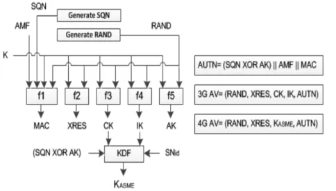
3.3 Generating an AV in the AuC . . . 34
3.4 Authentication message flow in 3G mobile systems . . . 35
3.5 Computations in the USIM . . . 36
4.1 Possible scenario for the man-in-the-middle attack . . . 51
5.1 Generating an AV in the novel scheme . . . 62
5.2 Computations at SIM in the novel scheme . . . 62
5.3 SIM-ME interactions to drop any established connection . . . 66
6.1 SIM-ME interactions to transfer the new IMSI . . . 84
7.1 Possible outcomes in a user linkability attack . . . 96
9.1 Additional computations for predefined multiple IMSIs . . . 115
9.2 Authentication message flow for modifiable multiple IMSIs . . . 119
9.3 Computations in AuC for modifiable multiple IMSIs . . . 119
9.4 Computations in USIM for modifiable multiple IMSIs . . . 121
9.5 Additional computations for the van den Broek et al. scheme [163] . . . 126
9.6 Authentication message flow for robust pseudo-IMSIs . . . 130
List of Tables
List of Algorithms
9.1 AV generation in robust pseudo-IMSIs . . . 133
9.2 Identity update in robust pseudo-IMSIs . . . 135
9.3 USIM process in robust pseudo-IMSIs . . . 137
List of Listings
5.1 Enhanced GSM AKA model: Summary of declarations . . . 73
5.2 Enhanced GSM AKA model: MS process (highlights) . . . 75
5.3 Enhanced GSM AKA model: SN process (highlights) . . . 76
5.4 Enhanced GSM AKA model: HN process (highlights) . . . 76
5.5 Enhanced GSM AKA model: Main process . . . 76
9.1 Modifiable multiple IMSIs model: Summary of declarations . . . 148
9.2 Modifiable multiple IMSIs model: UE process (highlights) . . . 149
9.3 Modifiable multiple IMSIs model: SN process (highlights) . . . 150
9.4 Modifiable multiple IMSIs model: HN process (highlights) . . . 151
9.5 Modifiable multiple IMSIs model: Main process . . . 151
9.6 Robust pseudo-IMSIs model: Summary of declarations . . . 153
9.7 Robust pseudo-IMSIs model: UE process (highlights) . . . 154
9.8 Robust pseudo-IMSIs model: SN process (highlights) . . . 156
9.9 Robust pseudo-IMSIs model: HN process (highlights) . . . 157
List of Notations
k Concatenation
⊕ Boolean exclusive-Or
A3 GSM authentication function
A5/1 GSM encryption algorithm # 1
A5/2 GSM encryption algorithm # 2
A5/3 GSM encryption algorithm # 3
A8 GSM key generation function
AK Anonymity key
AMF Authentication management field
AUTM Authentication token in pseudo-IMSI resynchronisation
AUTN Authentication token
AUTS Authentication token in SQN resynchronisation
c2 3GPP conversion function
c3 3GPP conversion function
CK 3GPP cipher key
EK Encryption key in the modifiable multiple IMSIs scheme
f1 3GPP network authentication function
f1∗ 3GPP resynchronisation message authentication function
f2 3GPP user authentication function
f3 3GPP cipher key derivation function
f4 3GPP integrity key derivation function
f5 3GPP anonymity key derivation function for normal operation
f5∗ 3GPP anonymity key derivation function for resynchronisation f5∗∗ Mask key derivation function for the robust pseudo-IMSIs scheme f5∗∗∗ Mask key derivation function for the robust pseudo-IMSIs scheme
IK 3GPP integrity key
K Subscriber authentication key
KASM E Local master key in EPS
Kc Cipher key in GSM
Ke Shared secret key in the van den Broek et al. scheme
MAC Message authentication code
MAC-M Message authentication code for pseudo-IMSI resynchronisation
MAC-S Message authentication code for SQN resynchronisation
RAND Random challenge
RES Authentication response
SMAC Sequence-MAC in the predefined/modifiable multiple IMSIs schemes
SQN Sequence number
SQNM S Sequence number suggested by mobile station
SRES Signed response in GSM
XMAC Expected MAC
XOR Boolean exclusive-Or
List of Abbreviations
1G First Generation
2G Second Generation
3G Third Generation
3GPP 3rd Generation Partnership Project
4G Fourth Generation
ADF Application Dedicated File
AKA Authentication and Key Agreement
APDU Application Protocol Data Unit
AuC Authentication Center
AV Authentication Vector
BCCH Broadcast Common Control Channel
BS Base Station
BSC Base Station Controller
BSS Base Station Subsystem
BTS Base Transceiver Station
CC Country Code
CEPT European Conference of Postal and Telecommunications Administrations
CRL Certificate Revocation List
CS Circuit Switched
DF Dedicated File
DMSI Dynamic Mobile Subscriber Identity
EF Elementary File
EIR Equipment Identity Register
eNB Evolved Node B
EPS Evolved Packet System
ETSI European Telecommunications Standard Institute
E-UTRAN Evolved UTRAN
GGSN Gateway GPRS Support Node
GMSC Gateway-MSC
GPRS General Packet Radio Service
GSM Global System for Mobile Communications
GSMA GSM Association
GUMMEI Globally Unique MME Identifier
GUTI Globally Unique Temporary UE Identity
HLR Home Location Register
HN Home Network
HSS Home Subscriber Server
IMAN International Mobile Anonymous Number
IMEI International Mobile Equipment Identity
IMEISV International Mobile Equipment Identity Software Version
IMS IP Multimedia Subsystem
IMSI International Mobile Subscriber Identity
IP Internet Protocol
ISIM IMS SIM
KDF Key Derivation Function
LA Location Area
LAC Location Area Code
LAI Location Area Identity
LTE Long-Term Evolution
MAC Message Authentication Code
MCC Mobile Country Code
ME Mobile Equipment
MF Master File
MME Mobility Management Entity
MNC Mobile Network Code
MNO Mobile Network Operator
MS Mobile Station
MSC Mobile Switching Center
MSIN Mobile Subscriber Identification Number
MSISDN Mobile Station International ISDN Number
MT Mobile Terminated
NDC National Destination Code
NMSI National Mobile Subscriber Identity
PLMN-ID Public Land Mobile Network Identity
PMSI Pseudo Mobile Subscriber Identifier
PS Packet Switched
PSTN Public Switched Telephone Network
RA Routing Area
RAC Routing Area Code
RAI Routing Area Identity
RAN Radio Access Network
RID Recovery Identity
RNC Radio Network Controller
SAT SIM Application Toolkit
SGSN Serving GPRS Support Node
S-GW Serving Gateway
SIM Subscriber Identity Module
SN Serving Network
SS7 Signalling System 7
STK SIM Toolkit
TA Tracking Area
TAC Tracking Area Code
TAI Tracking Area Identity
TESLA Timed Efficient Stream Loss-tolerant Authentication
TID Transient Identity
TMSI Temporary Mobile Subscriber Identity
UE User Equipment
UICC Universal Integrated Circuit Card
UMTS Universal Mobile Telecommunications System
USAT USIM Application Toolkit
USIM Universal Subscriber Identity Module
USRP Universal Software Radio Peripheral
USSD Unstructured Supplementary Service Data
UTRAN Universal Terrestrial Radio Access Network
Chapter 1
Introduction
1.1
Context of Research
Mobile phones have become an integral part of our daily lives. We use them at work, at home and everywhere in between to stay connected to the world around us. The growth in mobile subscribers over the years has been very substantial. At present, approximately sixty-three percent of the world population are connected to a mobile network [121].
The major growth in use of mobile networks started with the introduction of the
second generation (2G) GSM network in the early 1990s. We are now in the era of
fourth generation (4G) mobile networks; however, legacy mobile systems, i.e. GSM and
third generation (3G) mobile networks, continue to operate to support a large segment of the mobile subscribers [42, 134]. Even today, approximately forty-four percent of global connections use GSM technology and thirty percent use 3G mobile technology; as yet 4G mobile networks only support twenty percent of global connections [42]. Although 4G subscriptions are growing fast, legacy mobile systems remain of huge practical importance worldwide, and are unlikely to be replaced for many decades to come. Moreover, for practical reasons, all later generation mobile technology needs to support the earlier generation technology, which makes security flaws in legacy networks potential threats to all mobile subscribers. As a result, finding ways of improving the security offered by existing mobile systems is clearly of great practical significance.
A wide range of approaches [46, 48, 71, 81, 82, 108, 113, 116] have been proposed to improve the security and privacy features of GSM, 3G and 4G networks. However, they all require significant changes to the deployed network infrastructure; that is they require modifications to all the participating entities, i.e. to the serving networks, home networks, and mobile devices, as well as the network protocols. Unfortunately, it is clear
1.2. MOTIVATION
that making such modifications to widely deployed mobile systems is almost certainly impractical in practice. Prior to commencing the work described in this thesis, it was not known whether it is possible to improve the security and privacy properties of the current mobile systems without changing the deployed network infrastructure, i.e. the serving networks and mobile phones. Addressing this question has provided the main motivation for the work described in this thesis.
This chapter provides an overview of the thesis, and is organised as follows. In Section 1.2 we discuss the research motivation. Section 1.3 outlines the major con-tributions. A list of relevant publications is presented in Section 1.4, and Section 1.5 concludes the chapter with a brief outline of the thesis.
1.2
Motivation
While first generation (1G) mobile systems did not provide any security features, se-curity has been an integral part of such systems since the advent of 2G. For example, GSM, perhaps the best known 2G system, provides a range of security features, includ-ing authentication of the mobile user to the network, data confidentiality across the air interface, and a degree of user pseudonymity through the use of temporary identities. However, the absence of network authentication in GSM leaves the system open to a wide range of threats (see, for example, [125, 130, 136]). Despite the introduction and deployment of 3G (UMTS) and 4G (LTE) mobile systems, which rectify this shortcom-ing by providshortcom-ing mutual authentication between phone and network, GSM remains of huge practical importance worldwide and is unlikely to be replaced for many decades to come. As a result, incorporating new features to improve the security offered by GSM, without the need for changes to deployed phones, access networks, and protocols, is of great practical importance. This observation motivates the investigation of a novel scheme to include network-to-phone authentication in GSM mobile systems in a way that is completely transparent to the deployed network infrastructure.
Although the security properties of the 3G and 4G mobile networks have signifi-cantly improved by comparison with GSM, significant shortcomings remain with respect to user privacy. The possibility of user tracking by intercepting air interface traffic was considered in the design phase of the second generation GSM network, and was ad-dressed by the use of a changing pseudonym, thetemporary mobile subscriber identity
(TMSI), instead of the permanent international mobile subscriber identity (IMSI) for transmissions across the radio link. Newly allocated TMSIs are transmitted to the phone by the network in encrypted form to prevent linking of TMSIs or of a TMSI to the IMSI. The same mechanism was adopted in the 3G [162] and 4G [93] systems.
1.3. CONTRIBUTIONS
Although the temporary identity is used instead of the IMSI in most cases, in certain situations the IMSI is sent in cleartext by the mobile. One such case is when a mobile device is switched on and wishes to connect to a new network, and hence will not have an assigned temporary identity. Another case is where the network is unable to identify the IMSI from the presented temporary identity and is therefore obliged to request the transmission of the IMSI [31, 114]. An active adversary can exploit this and masquer-ade as a legitimate network to request the permanent identity [3]. Such an adversary is known as an ‘IMSI catcher’ [151], and is a threat to all generations of mobile networks. Although IMSI catchers were initially only available to government agencies because of their cost and complexity, advances in hardware technology and the availability of software has made IMSI catcher capabilities affordable for almost anyone. During the last couple of years, widespread use of unregulated IMSI catchers has been observed in a number of countries [45, 100, 150]. Security agencies have reported on the use of IMSI catchers by criminals and foreign intelligence agencies [66, 159], indicating that such attacks are now a serious issue.
Over the years, a wide range of possible solutions to the IMSI catcher problem have been proposed [48, 50, 71, 94, 108, 113, 142, 143]; unfortunately, they all require significant modifications to the air interface protocol, which would require changes to the operation of all the serving networks as well as all the deployed phones. As a result, it seems likely that making the necessary major modifications to the operation of the air interface after deployment is infeasible in practice. It would therefore be extremely valuable if a scheme to reduce the threat from IMSI catchers and thereby better protect user privacy could be devised which does not require significant changes to the existing network infrastructures and has minimal computational cost. This observation has motivated the work described in this thesis towards devising novel schemes to improve user identity privacy in mobile systems which could actually be deployed.
1.3
Contributions
In this thesis we describe the results of research into the possible enhancement of the security and privacy properties of the GSM, 3G and 4G mobile networks, as well as analyses of the deployability of certain previously proposed solutions. We further propose new schemes to add network authentication to GSM networks, and to enhance user identity privacy in the GSM, 3G, and 4G mobile networks without affecting the intermediate network entities, notably the serving networks and mobile equipment. Of the contributions, I formulated the research problem and came up with the proposed schemes, and my supervisor provided guidance and necessary corrections.
1.3. CONTRIBUTIONS
The main contributions of this thesis are as follows.
• Although many authors have proposed schemes designed to improve the security and privacy properties of GSM by providing mutual authentication and/or hiding the permanent subscriber identity, they all require changes to the existing radio interface protocols. It is somewhat counterintuitive to propose that authentica-tion of the network to the phone can be achieved without modifying the way in which the existing access networks and phones operate. However, this is what we have done. This apparently paradoxical result is achieved by using a technique we refer to as RAND hijacking. This involves using the authentication ‘challenge’
RAND, which serves as a nonce in the existing unilateral authentication protocol and is sent from the network to the phone, to contain data which enables the recipient SIM to verify its origin and freshness. That is, the RAND is hijacked to act as a communications channel between a home network and a SIM. We propose a novel authentication scheme for GSM where, instead of generating the
RAND at random, it contains information enabling the network to be authenti-cated; this information is sent in encrypted form so that to an eavesdropper it is indistinguishable from a random value. We provide a detailed analysis of the scheme and verify its correctness and security properties using ProVerif.
• We analyse certain recently proposed modifications to the operation of mobile systems intended to address user privacy threats. Specifically, we critically ex-amine the proposals of Arapinis et al. [48]. This analysis reveals that the proposed modifications are impractical in a variety of ways; not only are there security and implementation issues, but the necessary changes to the operation of the system are very significant and much greater than was envisaged by the authors. In fact, some of the privacy issues appear almost impossible to address without a complete redesign of the security system, meaning that making significant sys-tem changes to address some of them are unlikely to be worth the effort. The shortcomings of the proposed ‘fixes’ exist despite the fact that the modifications have been verified using a logic-based modelling tool, suggesting that such tools need to be used with great care. We also suggest possible alternative approaches to some of the modifications.
• We address the decades-old privacy problem of disclosure of the permanent sub-scriber identity (IMSI), a problem arising in all generations of mobile networks that makes IMSI catchers a real threat. A number of possible modifications to existing protocols have been proposed to address the problem; however, almost
1.4. PUBLICATIONS
all require significant changes to existing deployed infrastructures, and are there-fore impractical to implement in practice. We propose an approach which does not require any changes to the existing deployed network infrastructures, i.e. to the serving networks or mobile devices, but offers improved user identity protec-tion over the air interface. The proposed schemes make use of multiple IMSIs for an individual subscriber, thereby offering a degree of pseudonymity for a user. The only changes required are to the operation of the authentication centre in the home network and to the SIM/USIM, both owned by a single entity. We present two different approaches to the use and management of multiple IMSIs, and report on experiments to validate their deployability. The schemes could be deployed immediately since they are completely transparent to the existing network infrastructure.
We further improve our proposed scheme to address a possible shortcoming. The improved scheme prevents disclosure of the subscriber’s IMSI by using a dynamic pseudo-IMSI that is only identifiable by the USIM’s home network. A major chal-lenge in using dynamic pseudo-IMSIs is possible loss of identity synchronisation between a USIM and its home network, an issue which has not been adequately addressed in previous work. We present an approach for identity recovery to be used in the event of pseudo-IMSI desynchronisation. The scheme requires changes to the home network and the USIM, but not to the serving network, mo-bile phone or other internal network protocols, enabling simple, transparent and evolutionary migration. We discuss the strengths and limitations of the scheme, and verify its correctness and security properties using ProVerif.
1.4
Publications
Publications containing some of the research results described in this thesis are listed below.
• M. S. A. Khan and C. J. Mitchell, ‘Another look at privacy threats in 3G mobile telephony’, in: W. Susilo and Y. Mu (eds.),Information Security and Privacy— 19th Australasian Conference, ACISP 2014, Wollongong, NSW, Australia, July 7–9, 2014. Proceedings,Springer-Verlag LNCS 8544, Berlin (2014), pp.386–396. • M. S. A. Khan and C. J. Mitchell, ‘Improving air interface user privacy in
mo-bile telephony’, in: L. Chen and S. Matsuo (eds.), Security Standardisation Re-search, Second International Conference, SSR 2015, Tokyo, Japan, December
1.5. THESIS OUTLINE
15–16, 2015, Proceedings, Springer-Verlag LNCS 9497, Berlin (2015), pp.165– 184.
• M. S. A. Khan and C. J. Mitchell, ‘Retrofitting mutual authentication to GSM using RAND hijacking’, in: G. Barthe, E. Markatos and P. Samarati (eds.), Se-curity and Trust Management—12th International Workshop, STM 2016, Herak-lion, Crete, Greece, September 26–27, 2016, Proceedings, Springer-Verlag LNCS 9871, Berlin (2016), pp.17–31.
• M. S. A. Khan and C. J. Mitchell, ‘Trashing IMSI catchers in mobile networks’, in: G. Noubir and M. Conti and S. K. Kasera (eds.), 10th ACM Conference on Security and Privacy in Wireless and Mobile Networks, WiSec 2017, Boston, MA, USA, July 18-20, 2017. Proceedings,ACM (2017), pp.207–218.
All the previously mentioned publications were supervised by C. J. Mitchell. A further publication co-authored whilst conducting my PhD research is as follows.
• M. N. Kayuni, M. S. A. Khan, W. Li, C. J. Mitchell and P. Yau, ‘Generating unlinkable IPv6 addresses’, in: L. Chen and S. Matsuo (eds.), Security Stan-dardisation Research, Second International Conference, SSR 2015, Tokyo, Japan, December 15–16, 2015, Proceedings, Springer-Verlag LNCS 9497, Berlin (2015), pp.185–199.
1.5
Thesis Outline
The reminder of this thesis is divided into four parts, as follows.
1. Part I describes necessary background material. It contains two chapters, as follows.
• Chapter 2 describes those aspects of the system architecture, user identi-ties, air interface protocols, and services of 2G mobile systems necessary to understand the rest of the thesis.
• Chapter 3 outlines aspects of the system architecture, user identities, air interface protocols, and services of 3G and 4G mobile systems relevant to the rest of the thesis.
2. Part II describes the security and privacy threats arising from use of GSM. It fur-ther presents novel schemes to support mutual authentication, and to improve air interface user privacy in GSM networks. It contains the following three chapters.
1.5. THESIS OUTLINE
• Chapter 4 gives an overview of known security and privacy issues arising from the lack of mutual authentication and disclosure of the permanent subscriber identity in GSM networks. It also discusses previous attempts to address these issues.
• Chapter 5 describes and analyses a novel scheme to provide mutual authen-tication in GSM without affecting the serving networks or phones.
• Chapter 6 describes and analyses a scheme to improve air interface user privacy in GSM networks, that does not require modifications to the serving networks or phones.
3. Part III addresses privacy threats arising in 3G and 4G mobile systems. Novel schemes designed to address the threat of IMSI catchers in mobile networks are presented. It contains three chapters, as follows.
• Chapter 7reviews known privacy issues arising from disclosure of the perma-nent subscriber identity in 3G and 4G. It also discusses previous attempts to address these issues.
• Chapter 8 presents a critical analysis of the proposed modifications to the operation of 3G mobile systems due to Arapinis et al. [48], intended to ad-dress threats to user identity privacy; it further proposes possible alternative means of mitigating these threats.
• Chapter 9 describes and analyses novel schemes to address the decades-old privacy problem of disclosure of the permanent subscriber identity, focussing in particular on 3G and 4G.
4. Part IV concludes the thesis by summarising the main contributions as well as highlighting possible areas for future work. This part of the thesis consists of a single chapter,Chapter 10.
Part I
Overview
Part I describes necessary background material. It contains two chapters, as follows. • Chapter 2 describes those aspects of the system architecture, user identities, air
interface protocols, and services of 2G systems necessary to understand the rest of the thesis.
• Chapter 3 outlines aspects of the system architecture, user identities, air interface protocols, and services of 3G and 4G systems relevant to the rest of the thesis.
Chapter 2
2G Mobile Systems
2.1
Introduction
The 2G GSM1(global system for mobile communications) system, developed initially by theEuropean conference of postal and telecommunications administrations (CEPT) and then adopted by theEuropean telecommunications standard institute (ETSI), replaced the 1G analogue mobile systems. The first GSM system was developed in Finland by the operator Radiolinja in 1991, and GSM remains the most widely-used technology for wireless networks worldwide [42]. This chapter introduces those parts of the GSM technology relevant to the remainder of the thesis, with a particular focus on the security and privacy features.
The chapter is organised as follows. In Section 2.2 we briefly describe the archi-tecture of GSM. Section 2.3 outlines the identities used within a GSM network. In Section 2.4 we describe in detail the GSM authentication protocol, which underlies all the GSM security and privacy features. Section 2.5 outlines the GSM services key to this thesis. In Section 2.6 we describe relevant features of a SIM. Section 2.7 concludes the chapter by briefly reviewing thegeneral packet radio service (GPRS), a GSM-based 2G data communications technology.
2.2
System Architecture
Although the only visible part of a mobile network architecture is the set of intercon-nected and stationary radio towers distributed over the geographical coverage area of amobile network operator (MNO), there is a complex network behind the scenes pro-viding seamless wireless communication services. In this section we give a simplified
1Originally known as groupe sp`ecial mobile, GSM was renamed following the worldwide adoption
2.2. SYSTEM ARCHITECTURE
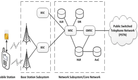
overview of the architecture of the GSM network, focusing on those entities that are of relevance to this thesis. Figure 2.1 illustrates the architecture and the connections between these components. Further details can be found in technical specifications GSM 03.02 [87] and 3GPP TS 43.020 [40].
2.2.1 Overview
The infrastructure for a GSM network can be divided into two subsystems: the base station subsystem (BSS) and the network subsystem. The stationary radio towers be-long to the BSS. To attach to a network, a mobile phone, a mobile station in GSM terminology, connects via its radio interface to a radio tower. The radio tower, also known as abase transceiver station (BTS) or simply a base station (BS), relays radio traffic to and from the mobile network and provides over-the-air access to the network. Each BTS covers a specific area called acell, and is identified by its cell identity. Cells are grouped together to form alocation area (LA), which is controlled by a singlebase station controller (BSC). The BTSs and BSCs form the BSS, also known as theradio network, which contains the functionality necessary to enable mobile users to connect to the network over the radio interface. The radio interface is usually referred to as the
air interface.
Figure 2.1: GSM system architecture (simplified)
The network subsystem is the back-end component of the GSM network architec-ture, and is known as the core network. The mobile switching center (MSC) is the controlling element of a core network. A number of BSCs are connected to a sin-gle MSC, and the MSC is responsible for controlling call setup and routing, and for
2.2. SYSTEM ARCHITECTURE
mobility management. The gateway-MSC (GMSC) connects the mobile network to the public switched telephone network (PSTN)—the global telephony network. Two separate databases contain subscriber account information, namely the home location register (HLR) and the visitor location register (VLR); these databases form part of the core network, and are connected to the MSC to support its operation, for example, for authentication of subscribers, location management, and organizing handover to a BSC. The VLR holds dynamic information regarding the subscribers currently roam-ing in the jurisdiction of the MSC, information which is maintained until the subscriber is handed over to a different MSC.
Each MNO maintains a HLR that is used to store information about its subscribers. The HLR holds a record for each subscriber, where a record contains the following information:
• the subscriber’s permanent identity, known as the IMSI;
• the subscriber’s phone number;
• the set of services available to this subscriber;
• the identity of the MSC currently responsible for forwarding mobile terminated services to this subscriber; and
• the subscriber-specific authentication data.
Although a subscriber is normally assigned only a single phone number, an HLR could store multiple phone numbers for a subscriber. Generally there is only one HLR for an MNO; however, an MNO could implement the HLR in a distributed way to support a large numbers of users. The HLR is associated with anauthentication center
(AuC) that stores the cryptographic credentials required for communicating with the SIM; specifically, the AuC shares a unique secret key K with each SIM issued by the MNO to which it belongs, and is responsible for computing subscriber-specific authentication data.
The equipment identity register (EIR) is a database of the identities of mobile de-vices used in the global GSM network. A mobile device identity, known asinternational mobile equipment identity (IMEI) (see Section 2.3.2 below), can be classified as white-listed,grey-listed, orblack-listed. The EIR enables the MSC to prevent specific mobile devices, e.g. banned or stolen mobile phones, from accessing its services. The possible use of the EIR in a GSM network is discussed in Section 4 of the technical specifications GSM 02.16 [85] and 3GPP TS 22.016 [21]. Each MSC of a GSM network is connected to the EIR; a centralised EIR could serve the MNOs in a specific region.
2.2. SYSTEM ARCHITECTURE
2.2.2 Security Context Classification
The entities in GSM network architecture can be grouped into the three categories described below, where the categories are based on the trust inter-relationships. We use these categories when describing security-related functionality in the remainder of the thesis.
2.2.2.1 Mobile Station
A complete mobile phone is referred to as a mobile station (MS), where the term encapsulates not only themobile equipment (ME), i.e. the phone, but also thesubscriber identity module(SIM) within it, where the SIM takes the form of a cut-down smart card. The ME is made up of components which may have been designed and manufactured by a range of vendors, whereas the SIM is always owned and managed by the subscriber’s MNO. The ME must support all the mandatory features of the GSM standards, and is known as a2G ME. The SIM embodies the relationship between the human user and the issuing MNO, including the IMSI, the mobile number, and other user (subscriber) data, together with a secret key K shared with the issuing network which forms the basis for all the air interface security features. Further details of the SIM are given in Section 2.6.
2.2.2.2 Serving Network
The radio network, along with the MSC and its associated VLR, forms part of the
serving network (SN). This is the network from which a subscriber receives telecom-munication services. To support roaming subscribers, the SN could be managed by an MNO different from the MNO with which the subscriber has a contract for the provision of mobile services. This arrangement needs to be supported by a roaming agreement between the MNOs concerned. Given the absence of a subscriber agreement between a roaming subscriber and an SN, there is no direct trust relationship between them, although there is an indirect relationship since the SN is trusted by the home network, as described in the next section. However, the SN must follow the protocol specification when communicating with the MS and home network.
2.2.2.3 Home Network
The HLR and the AuC operated by a single MNO together form the home network
(HN) component of a mobile network. The HN is the source of trust for the user of a mobile network, and is individually managed by each MNO. The HN is responsible for subscriber authentication, authorisation, and cryptographic key generation. As
2.3. SYSTEM IDENTITIES
mentioned above, the AuC stores the subscriber’s secret key K, and is responsible for computing authentication data and cryptographic keys for an individual subscriber; given its sensitivity, access to the AuC is restricted to the HLR.
2.3
System Identities
2.3.1 IMSI
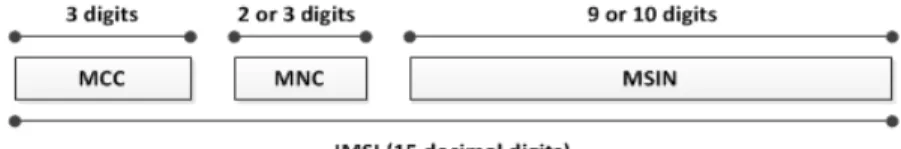
An IMSI is a string of 15 decimal digits which uniquely identifies a GSM subscriber worldwide; it is used for subscriber-related signalling in the network. The structure of an IMSI is defined in technical specifications GSM 03.03 [5], 3GPP TS 23.003 [23] and E.212 [157]. As stated above, it is stored in the subscriber’s SIM and in the HLR; it is the key to all information about subscribers. An IMSI is made up of the following three parts (see Figure 2.2).
Figure 2.2: Structure of an IMSI
• Mobile Country Code(MCC): The first three digits of an IMSI are the MCC that identifies the subscriber’s home country. The allocation of MCCs is administered by the ITU-T (the Telecommunication standardisation sector of the International Telecommunications Union)2.
• Mobile Network Code (MNC): The next two or three digits uniquely identify the MNO of a subscriber within the country identified by the MCC, and are known as the MNC. The length of the MNC, i.e. whether it is two or three digits, is a national matter, and MNC values are managed by the national administrator. A unique MNC is necessary because there are usually multiple mobile networks within a country. In the United Kingdom, for example, the following MNCs are used: 10 for O2, 15 for Vodafone, 30 for T-Mobile, and 33 for Orange.
• Mobile Subscriber Identification Number (MSIN): The remaining nine or ten dig-its form the MSIN, and are administered by the network operator. The MSIN uniquely identifies a subscriber of an MNO.
2
2.3. SYSTEM IDENTITIES
IMSIs thus have geographical significance, and are typically managed by the net-work operator in blocks. The MCC and MNC combination uniquely identifies the HN, and is known as thepublic land mobile network identity (PLMN-ID); analogously, the MNC and MSIN combination uniquely identifies a subscriber within a national context, and is known as the national mobile subscriber identity (NMSI). The MSIN is used by the network operator to identify the subscriber for billing and other operational purposes. So, each IMSI uniquely identifies the mobile user, as well as the user’s HN and home country; hence, it has privacy and security significance. The IMSI for a subscriber is normally fixed.
2.3.2 IMEI
An IMEI is a string of 15 decimal digits used to uniquely and permanently identify an ME, allowing a stolen equipment to be blacklisted in the EIR. It plays no role in the provision of communication services, and a network cannot verify its authenticity. It might be accompanied by a software version number, in which case the identity is called an international mobile equipment identity software version (IMEISV). Be-cause of possible software upgrades to a terminal, the IMEISV might change during the terminal’s lifetime, while the IMEI remains the same. Although the technical spec-ifications [6, 24] describe an IMEI as temporary subscriber data, subscribers typically use a mobile device for a significant period of time; hence, an IMEI is quasi-permanent, and if sent in cleartext it could compromise user privacy. Further details can be found in technical specifications GSM 03.03 [5], and 3GPP TS 23.003 [23].
2.3.3 MSISDN
The phone number of a subscriber, known in GSM as themobile station international ISDN number (MSISDN) [86], is a string of up to 15 decimal digits, of which the first three are the country code (CC), the international code of the subscriber’s home country. The remaining digits are the national mobile number, which consists of a
national destination code (NDC) and a unique subscriber number. The composition of the MSISDN is such that it can be used as a global address in the core network for routing data to the HLR of the MS. The CC and the NDC provide the necessary routing information, and the MSISDN is used in delivering mobile terminated (MT) services (see Section 2.5.4). If further routing information is required, it should be contained in the first few digits of the subscriber number [5, 158]. Since the introduction of mobile number portability blurs the significance of the NDC, routing data can if necessary be obtained by other means. Further details can be found in the relevant
2.4. AUTHENTICATION PROTOCOL
standards [5, 23, 158].
The MSISDN is typically public information for a subscriber. It is not used to identify a subscriber in the network, and is not included in the signalling messages sent across the air interface. As a result, it is outside the scope of this thesis, and we do not consider it further here.
2.3.4 TMSI
As discussed in Section 1.2, a TMSI is a temporary subscriber identity used in place of an IMSI in transmissions across the air interface, with the goal of providing user pseudonymity. The TMSI is allocated by the MSC, and is transferred to the MS via an encrypted channel. The MSC maintains the relationship between a TMSI and its associated IMSI. Since the MSC uses the subscriber’s IMSI in communications across the core network, maintaining the mapping of an IMSI from a TMSI is critical for successful network operation. We discuss this issue in detail in the next chapter (see Section 3.7).
A TMSI consists of four octets. Since a TMSI has only local significance, i.e. within an MSC and the area controlled by an MSC, its structure and coding are chosen by the SN [5, 23]. When a subscriber moves from one LA to another, its TMSI is updated by the SN. Although a subscriber is temporarily traceable via its TMSI, the length of time a single TMSI remains valid is limited, and is configurable by the SN.
2.3.5 LAI
Alocation area identity (LAI) uniquely identifies an LA within a mobile network, where LAs are geographical sub-divisions of the area covered by a single MSC. An LAI is a combination of the PLMN-ID of the mobile network and a location area code (LAC). A LAC is two bytes long, and is managed by an MSC [5, 23].
2.4
Authentication Protocol
To prevent unauthorised MSs gaining access to network service, GSM incorporates an authentication procedure which enables the network to verify that the SIM in an MS is genuine, and has the identity it claims. This procedure is known as the GSM
authentication and key agreement (AKA) protocol; this protocol is at the core of air interface security, since it also establishes a session key used for subsequent traffic encryption.
2.4. AUTHENTICATION PROTOCOL
The AKA is performed between the MSC of the SN and the MS as part of a range of network operations, including when:
• a change is necessary to the subscriber-related information element in the VLR or HLR, including one or both of;
– a location update involving change of MSC,
– the activation or deactivation of a supplementary service;
• an MS attempts to access a service, such as a mobile originating or a mobile terminating service; or
• an MS makes its first network access after a restart.
Although user identification is not part of the AKA protocol, it is an implicit prerequisite for executing the protocol. In the user identification phase, the MS will, whenever it can, identify itself using its TMSI, and the MSC determines the IMSI from the TMSI using its own process. If the MSC fails to determine the IMSI from the supplied TMSI, it requests the MS to send its IMSI using a user identity request
message; the MS responds with its cleartext IMSI in auser identity response message. Once the SN learns the IMSI, it selects the next unused element from an IMSI-specific list ofauthentication vectors (AVs), stored in the SN’s VLR. The AV contains all the data necessary to perform AKA. If the list is empty, the SN determines the subscriber’s HN by parsing the IMSI, and contacts this network to request a new set of AVs, which are typically sent in small batches (to overcome latency).
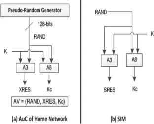
On receipt of such a request, the HN’s AuC retrieves the secret key K for the specified IMSI, and uses it to generate a batch of AVs. These AVs are generated using a pair of cryptographic functions known asA3 and A8. These functions only need to be implemented by the HN and the SIMs it issues, and the choice of functions is up to the network; nevertheless, the3rd generation partnership project (3GPP)3recommends use of the corresponding 3G functions in a modified way [41]. The function A3 is a 32-bit MAC generating function andA8 is a 64-bitkey derivation function (KDF).
Generating an AV involves the following steps (see Figure 2.3(a)); which can be repeated as necessary to generate a batch.
1. A 128-bit random (or pseudorandom) valueRAND is generated. 2. The AuC computes the 32-bit value XRES asXRES =A3K(RAND).
3
2.4. AUTHENTICATION PROTOCOL
3. The AuC computes the 64-bit keyKcasKc =A8K(RAND).
4. AV = (RAND,XRES,Kc).
The generated AVs are then sent back to the SN, which can then use one of them to conduct AKA.
The core of AKA is a challenge-response protocol. The messages exchanged among the involved parties, i.e. the MS, the SN, and the HN, are shown in Figure 2.4, and the computations involved are shown in Figure 2.3.
Figure 2.3: Computations of GSM AKA key values
The challenge-response procedure operates as follows. Further details can be found in technical specifications GSM 03.20 [2], 3GPP TS 43.020 [40] and GSM 04.08 [7].
1. The serving MSC sends RAND to the MS as an authentication challenge. The ME passes the received RAND to the SIM using theRUN GSM ALGORITHM
command.
2. The SIM computesSRES =A3K(RAND) andKc =A8K(RAND), whereA3 and
A8 are the same functions as used by the HN to generate the AV,SRES is a 32-bit
signed response, and Kc is a 64-bit session key used to encrypt data sent across
the air interface. Note that precisely the same computation was performed by the AuC to generateXRES and Kcearlier (see Figure 2.3(b)).
3. The SIM returnsSRES and Kcto the ME. The ME keeps the session keyKc to
use in data encryption, and forwards SRES to the serving MSC.
4. The serving MSC compares the receivedSRES with the value ofXRES from the AV; if they agree then the MS is deemed authenticated.
2.5. NETWORK ACTIVITIES
Figure 2.4: GSM AKA message flow
After successful authentication of an MS by a serving MSC, both the MS and the MSC hold a valid session keyKc. The MSC transfers this key to the appropriate BSC,
where it is used for traffic encryption using one of the standardised algorithms (i.e. one of A5/1, A5/2 and A5/3), as selected by the BSC of the SN. The serving MSC also assigns a TMSI and sends it to the MS; the BSC will encrypt the TMSI prior to transmission across the air interface, just as it does for voice traffic.
2.5
Network Activities
We next summarise certain network operations of particular relevance to security and privacy.
2.5.1 IMSI Attach
After a mobile device is switched on, its first action is to register with the network to enable it to send and receive calls. This is achieved using the IMSI attach process.
Radio communication between the MS and the SN takes place over various types of channel, including dedicated channels, shared channels and broadcast channels. When a mobile device is switched on, it listens for aSYSTEM INFORMATION message ad-vertised by a network over a broadcast channel known as thebroadcast common control
2.5. NETWORK ACTIVITIES
channel (BCCH). Such messages contain a range of information about the network, including the PLMN-ID of the radio tower; the identification of the radio tower, con-sisting of the LAC and the cell identity; and the frequencies used by neighbouring cells. On receiving the message, the MS compares the PLMN-ID values in the message with the list of permitted networks stored in its SIM. If there is a match, the MS responds to the network with a channel request and, as soon as a channel is assigned, the MS initiates the attachment process (see Figure 2.5).
Figure 2.5: Steps in mobile station attachment
The IMSI attach procedure is described in Section 4.4.3 of technical specification GSM 04.08 [7]. It is accomplished using the location update procedure, where the
update type information element in thelocation update request message sent by the MS to the network indicates IMSI attach. Thislocation update request message includes the IMSI of the MS. On receiving the message, the SN authenticates the MS using AKA, described in Section 2.4. If authentication is successful, the SN updates the location information of the subscriber at the subscriber’s HN (see Section 2.5.2 below), and notifies the MS; otherwise, the SN sends the MS a reject message. After a successful IMSI attach, the MS is sent a TMSI, which is used as its identifier in subsequent communication.
2.5.2 Location Update
When a subscriber moves to a new location area, the HN must be notified so that the MS can continue to receive mobile-terminated services (see Section 2.5.4), e.g. receiving calls or texts. An MS can initiate a location update procedure with the SN for a range of reasons, e.g. for a periodic location update to inform the network of its presence in a certain location area; normal location update because of a change of location
2.5. NETWORK ACTIVITIES
area; or during an IMSI attach. The reason for the location update is indicated in theupdate type field in the location update request message [7]. The main steps in the location update procedure are listed below. Further details can be found in technical specifications GSM 03.20 [2], GSM 04.08 [7], and GSM 03.12 [83].
1. The MS sends alocation update request message containing its TMSI and LAI to the MSC of the SN.
2. If the MSC in the SN is the same as that indicated by the LAI, the serving MSC determines the IMSI from the TMSI using its VLR; otherwise, it follows the process described in technical specification GSM 09.02 [8] to collect the cor-responding IMSI, along with any unused AVs, from the ‘old’ MSC, i.e. the MSC which was most recently connected to the MS. If the serving MSC fails to deter-mine the IMSI by this method, it requests the MS to send its IMSI using auser identity request message, and the MS responds with its cleartext IMSI in auser identity response message.
3. The SN performs the AKA protocol, enables ciphering with the new key, and allocates a new TMSI to the MS as described in Section 2.4; it then initiates a location update with the HN, involving the following steps.
(a) The serving MSC sends its identifier and the IMSI in a location update request message to the subscriber’s HN.
(b) On receiving the message, the HN updates the location information for the subscriber identified by the IMSI, and sends acancel location request to the ‘old’ MSC for this subscriber.
(c) The old MSC sends an acknowledgement for the location cancellation to the HN.
(d) The HN sends an acknowledgement for the location update request to the initiating MSC.
4. The SN sends a location update accept or location update reject message to the MS.
2.5.3 Paging
Pagingis used by an SN to locate an MS to which a connection needs to be established. In order to deliver a service to a user, the serving MSC needs to know the precise location of the MS. An ME typically reverts to an idle state most of the time to save
2.6. THE SIM
stored battery energy, and is therefore not in constant contact with the SN; thus the SN does not know which radio tower provides the best radio signal to the MS. However, the SN is aware of the location area in which the MS was most recently, and so it broadcasts a paging message throughout the location area to alert the MS.
A paging message is sent from the SN to all mobile devices in a particular area, and contains either an IMSI or a TMSI. The GSM standard [7] specifies three types of paging requests, known as type 1, type 2, and type 3 paging messages. The three paging message types allow different numbers of MSs to be addressed with a single message. Types 1, 2 and 3 paging messages respectively allow one or two, two or three, or four MSs to be paged simultaneously. If an MS detects a paging message containing its IMSI or its current TMSI, it establishes a dedicated channel with the SN and sends the network apaging response message containing its current TMSI.
2.5.4 Mobile Terminated Services
How a network service is managed varies depending on whether the service originates or terminates at an MS. A mobile terminated (MT) service is one that is passively received by a subscriber, e.g. receiving a phone call or a short message.
The MT services are supported by the paging procedure. When an MT service is to be delivered, the core network first determines the responsible MSC for the target subscriber with the help of the subscriber’s HLR. Next, the MSC obtains the location information for the destination subscriber from the VLR, and sends a paging message
to all BSCs in the subscriber’s location area. The message contains the identity of the subscriber, usually either an IMSI or a TMSI. The BSC broadcasts the paging message via all the BTSs in its jurisdiction. If the target subscriber responds with a
paging response message, it undergoes an authentication, ciphering and service setup procedure with the SN; the pending service is subsequently delivered to the MS. Paging in mobile systems could be spoofed; we discuss this issue further in Section 4.5.5.
2.6
The SIM
The SIM is the cornerstone of GSM security, since it contains the IMSI and the associ-ated 128-bit permanent keyK. The cryptographic mechanisms used in authentication and key generation, i.e.A3 andA8, are implemented in the SIM. The properties of the SIM are specified in technical specifications GSM 02.17 [84] and 3GPP TS 42.017 [4]. In the original GSM specification and until release 4 of the 3GPP specifications4, the physical smart card itself was called a SIM, so the specifications use the term ‘a SIM
4
2.6. THE SIM
card’. From release 4 of the 3GPP specifications, the smart card itself is called a uni-versal integrated circuit card (UICC), and the term SIM now refers to an application running in the UICC. This change of approach allows for later generation network access applications, e.g. theuniversal subscriber identity module (USIM) and theIMS SIM (ISIM), to run on the same smart card platform. The UICC supports communi-cations between the ME and an application in a UICC through well definedcommands. The properties of the UICC are defined in technical specification ETSI TS 102.221 [88]. In this section we briefly describe the data storage capabilities of a UICC, focussing on the SIM and the USIM application, communications between an application residing in a UICC and the ME, and a feature of the SIM, known as theSIM application toolkit, that is of great use in designing the schemes we describe later in the thesis.
2.6.1 Memory Structure
A UICC stores data in a file system organised as a rooted tree with at most one file associated with each node. File types included elementary files (EFs) and dedicated files (DFs). Each EF stores a set of data units, records or objects. EFs are always leaf nodes in the tree, and DFs are used to group EFs; thus a DF is only a leaf node if it is empty. The master file (MF) is a mandatory and unique DF that serves as the root of the file system tree. Files can be addressed in various ways, depending on the file type; for example, they can be addressed by variable-length names or by two-byte identifiers, which may be concatenated to absolute and relative paths. Basic actions, e.g. read or update, on UICC data are controlled by access conditions which must be satisfied before the action can be performed. The access control policies are defined in 3GPP specifications [10, 12].
An application in a UICC consists of a set of functions, and has an associated subtree in the file system. The application’s root DF is called anapplication dedicated file (ADF). Such ADFs are addressed by their unique DF name which must be listed in theEFDIR— an application-independent file that is a descendant of the MF. When
an ME initially accesses the UICC, if the EFDIR is not found in the UICC, or if the
USIM application, which has identifierADFUSIM, is not listed in theEFDIR, the UICC
selects the SIM application; hence, a UICC must always contain the SIM application. Both the SIM and USIM applications store a range of data about the subscriber, the supported services, and the network. For example, they store the subscriber’s IMSI, phone number, current location, and subscriber-specific cryptographic creden-tials. These data are stored in specific EFs, e.g. the IMSI is stored in the EFIMSI.
The SIM data storage requirements are specified in Section 6 of technical specifications GSM 02.17 [84] and 3GPP TS 42.017 [4]. Figure 2.6 shows the simplified file structure
2.6. THE SIM
Figure 2.6: UICC file structure (simplified) [12, 28]
of a UICC supporting both the SIM and the USIM applications.
Although the EFIMSI and theEFMSISDN files are present for both the SIM and the
USIM applications, their file names and the file identifiers for the two applications are identical (see Figure 2.6). TheseEFs contain the same information for use in different networks. This allows for memory efficient implementation of a SIM together with a USIM, since the files can be shared by the two applications.
2.6.2 Application Protocol Data Units
Data is exchanged between an application residing in a UICC and the ME in the form of application protocol data units (APDUs). An APDU sent by the ME is called a
command APDU, and is answered by the application residing in the UICC using a
response APDU. A matching pair of messages is referred to as a command–response
2.6. THE SIM
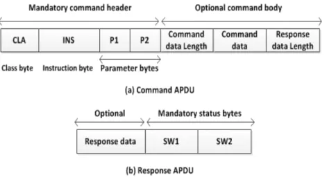
Figure 2.7(a) shows the structure of a command APDU. The first four bytes, known as thecommand header, are mandatory. Theclass byte specifies a group of commands, i.e. the value ‘A0’ indicates commands for the SIM application. The code transmitted in the instruction byte indicates a specific command, telling the application which operations to perform. Command arguments are encoded in the parameter bytes P1
andP2. The remaining parts of the command APDU are optional, where thecommand data length denotes the number of input bytes contained in the command data field, and is present if the command APDU carries additional data. Theresponse data length
encodes an upper bound for the size of the result data in the expected response APDU.
Figure 2.7: Command and response APDU
Figure 2.7(b) shows the structure of a response APDU. The response data is op-tional, and is present if the instruction specified in the command APDU generates response data. Thestatus bytes, SW1 and SW2, are mandatory, and respectively cat-egorise the outcome of the finished operation, and inform the ME about necessary follow-up commands. Further details can be found in technical specification ETSI TS 102.221 [88].
2.6.3 The SIM Application Toolkit
TheSIM application toolkit (SAT) is a service operating across the SIM–ME interface that provides a mechanism for a SIM to initiate an action to be taken by the ME. As discussed in the previous section, communications between an ME and a SIM are command–response based; the SAT provides a set of commands, also known as SIM toolkit (STK) commands, which allow a SIM to initiate an action with an ME. A SIM that supports the SAT is known as aproactive SIM.
2.7. GENERAL PACKET RADIO SERVICE
The GSM technical specification [12] states that an ME must communicate with a SIM using either the T=0 or T=1 protocol, specified in ISO/IEC 7816-3 [106]. In both cases the ME is always the master and thus initiates commands to the SIM; as a result there is no mechanism for the SIM to initiate communications with the ME. This limits the possibility of introducing new SIM features requiring the support of the ME, as the ME needs to know in advance what actions it should take. The proactive SIM provides a mechanism that allows the SIM to indicate to the ME, using a response to an ME-issued command, that it has some information to send. The SIM achieves this by including a special status byte ‘91’ followed by the length of the instruction to send in the response APDU, which signals both the successful termination of the ME’s last command as well as the length of the information describing the pending proactive command. The ME is then required to issue the FETCH command to retrieve the proactive command [9, 13]. The SIM responds with the proactive command, and the ME must execute it and return the result in theTERMINAL RESPONSE command. To avoid cross-phase compatibility problems, this service is only permitted to be used between a SIM and an ME that support the STK commands. The fact that an ME supports specific STK commands is revealed when the ME sends the TERMINAL PROFILE command during SIM initialisation.
The SIM can make a range of requests using the SAT service. Examples include: requesting the ME to display SIM-provided text, initiating the establishment of on-demand channels, and providing local information from the ME to the SIM. Although support of STK commands is optional for an ME, if an ME claims compliance with a specific GSM release then it is mandatory for the ME to support all functions of that release [13]. Since 1998 almost all of the MEs produced have been SAT-enabled, and today almost every ME on the market supports SAT. Further details can be found in technical specifications GSM 11.14 [13] and 3GPP TS 51.014 [9].
2.7
General Packet Radio Service
The general packet radio service (GPRS) is a GSM-based 2G data communication technology. Originally, GSM only supportedcircuit-switched (CS) data, for voice com-munications and short messages. GPRS is a backward-compatible update to GSM supporting the transfer of packet-switched (PS) data in a GSM network. Support for PS data is achieved by including additional entities, i.e. the SGSN and the GGSN, in the core network.
The GPRS security functions, i.e. the authentication of a subscriber and cipher key management, remain the same as in GSM. However, there are changes to certain
2.7. GENERAL PACKET RADIO SERVICE
network operations. Significant changes in GPRS systems include the following. • GPRS introduces an additional temporary subscriber identity, known as the
P-TMSI.
• GPRS uses a separate session key for GPRS data encryption.
• GPRS employs a new location identity, known as therouting area identity (RAI), analogous to the LAI in GSM.


![Figure 2.6: UICC file structure (simplified) [12, 28]](https://thumb-us.123doks.com/thumbv2/123dok_us/1425985.2690860/45.918.223.743.158.684/figure-uicc-file-structure-simplified.webp)

![Figure 3.2: 4G systems architecture (simplified) [25, 37]](https://thumb-us.123doks.com/thumbv2/123dok_us/1425985.2690860/52.918.241.715.166.446/figure-g-systems-architecture-simplified.webp)