TORQUE RIPPLE MINIMIZATION
COMMUTATION AND SPEED, CURRENT CONTROLLERS
1,*
Manoranjan Soora and
1
Assoc. Professor, Warangal Institute of Technology and Science,
2
Asst. Professor, EEE Dept, Vaagdevi College of Engineering, Warangal, A.P. India
ARTICLE INFO ABSTRACT
Brushless DC motors are having a major problem with harmonics in torque. The variations in speed and production of noise should be minimized by using proper topologies.
gaining attention fro
high efficiency, high power density and easy maintenance and low cost. This paper presents a three phase BLDC motor with low cost drive to be driven without DC link capacitor. Th
technique uses an electronic commutation and operates the machine exclusive of the intermediate DC link capacitor. The designing of Brushless DC motor drive system along with control system for torque ripple minimization, speed controller and cu
SIMULINK and results are evaluated.
Copyright©2017, Manoranjan Soora and Mekala Soujanya
permits unrestricted use, distribution, and reproduction in any medium, provided the original work is properly cited.
INTRODUCTION
Permanent Magnet Synchronous (PMS) motors and Brushless DC (BLDC) motors are becoming more useful
applications and home appliance because of their high reliability, efficiency and low cost and maintenance compared to other motors. By using rotor position BLDC motors are commutated electronically and the rotor position information can be obtained by using position sensors. BLDC and PMS motors are now designed with high power densities, these causes the increasing their popularity in applications such as airspace applications and mobile coolers. PMS motors needs continuous rotor position information for their operation and a significant computational time is required to improve the motor performance by controlling the rotor. Hall Effect sensors or back emf sensing technique is used to obtain the rotor position of BLDC motor for every 60 elec
Therefore, BLDC motors have becoming more popular for industrial applications where efficiency, compact and cost effective factors are considered. The motor drive consists of a diode bridge rectifier and a large electrolytic capacitor with converter fed rotor for rotor position information.
*Corresponding author: Manoranjan Soora,
Assoc. Professor, Warangal Institute of Technology and Science Warangal, A.P. India.
ISSN: 0975-833X
Article History: Received 27th July, 2017 Received in revised form 14th August, 2017
Accepted 24th September, 2017 Published online 31st October, 2017
Citation: Manoranjan Soora and Mekala Soujanya
speed, current controllers”, International Journal of Current Research
Key words:
Brushless Machines, Torque ripple Compensation, six-Phase Voltage Source Inverter (VSI), Harmonics Suppression, Pulse width Modulation (PWM).
RESEARCH ARTICLE
TORQUE RIPPLE MINIMIZATION OF A BLDC MOTOR DRIVE BY USING
COMMUTATION AND SPEED, CURRENT CONTROLLERS
Manoranjan Soora and
2Mekala Soujanya
Warangal Institute of Technology and Science, Warangal, A.P. India
. Professor, EEE Dept, Vaagdevi College of Engineering, Warangal, A.P. India
ABSTRACT
Brushless DC motors are having a major problem with harmonics in torque. The variations in speed and production of noise should be minimized by using proper topologies.
gaining attention from different Industrial and domestic appliance manufacturers, because of their high efficiency, high power density and easy maintenance and low cost. This paper presents a three phase BLDC motor with low cost drive to be driven without DC link capacitor. Th
technique uses an electronic commutation and operates the machine exclusive of the intermediate DC link capacitor. The designing of Brushless DC motor drive system along with control system for torque ripple minimization, speed controller and current controllers are presented using MATLAB / SIMULINK and results are evaluated.
Manoranjan Soora and Mekala Soujanya. This is an open access article distributed under the Creative Commons Att use, distribution, and reproduction in any medium, provided the original work is properly cited.
Permanent Magnet Synchronous (PMS) motors and Brushless DC (BLDC) motors are becoming more useful in industrial applications and home appliance because of their high reliability, efficiency and low cost and maintenance compared to other motors. By using rotor position BLDC motors are commutated electronically and the rotor position information obtained by using position sensors. BLDC and PMS motors are now designed with high power densities, these causes the increasing their popularity in applications such as PMS motors needs formation for their operation and a significant computational time is required to improve the Hall Effect sensors or back emf sensing technique is used to obtain the rotor position of BLDC motor for every 60 electrical degrees. Therefore, BLDC motors have becoming more popular for industrial applications where efficiency, compact and cost The motor drive consists of a diode bridge rectifier and a large electrolytic capacitor with a converter fed rotor for rotor position information.
Professor, Warangal Institute of Technology and Science,
The main function includes, bus voltage stabilization, ripple current conduction due to switching events, etc. In automotive applications, one of the major problems is the exuberant and barbarous temperatures they have to withstand, under hood, which during the summer months would reduce their life. intermediate DC link capacitor used in indirect conversion topologies, requires a large space for its installation which results in increasing its weight and occupying place. Usually, a large electrolytic capacitor is employed to support the intermediate DC link voltage.
The lifetime and properties associated with the capacitor are affected by the ambient temperature. Furthermore, the type of dielectric material, the ambient temperature and the storage temperature are the most significant aging factors for an electrolytic capacitor mainly in hot or cold environments viz. heating, ventilation and air conditioning applications. So the inclusion of the capacitor in the circuit decreases the overall converter reliability, as it is the most vulnerable component amongst the other in the circuit. Without the DC link capacitor, the rectified mains supply is directly applied to the drive. The absence of DC link capacitor causes to reduce the overall cost of the motor drive but at the expense of harmonics in torque, which are inevitable and expected to be around zero crossing points of the supply.
International Journal of Current Research
Vol. 9, Issue, 10, pp.59729-59735, October, 2017
OF CURRENT RESEARCH
Manoranjan Soora and Mekala Soujanya. 2017. “Torque ripple minimization of a BLDC motor drive by using electronic commutation and
International Journal of Current Research, 9, (10), 59729-59735
OF A BLDC MOTOR DRIVE BY USING ELECTRONIC
COMMUTATION AND SPEED, CURRENT CONTROLLERS
Warangal, A.P. India
. Professor, EEE Dept, Vaagdevi College of Engineering, Warangal, A.P. India
Brushless DC motors are having a major problem with harmonics in torque. The variations in speed and production of noise should be minimized by using proper topologies.BLDC motors have been m different Industrial and domestic appliance manufacturers, because of their high efficiency, high power density and easy maintenance and low cost. This paper presents a three phase BLDC motor with low cost drive to be driven without DC link capacitor. The proposed technique uses an electronic commutation and operates the machine exclusive of the intermediate DC link capacitor. The designing of Brushless DC motor drive system along with control system for rrent controllers are presented using MATLAB /
is an open access article distributed under the Creative Commons Attribution License, which
The main function includes, bus voltage stabilization, ripple current conduction due to switching events, etc. In automotive applications, one of the major problems is the exuberant and barbarous temperatures they have to withstand, under hood, g the summer months would reduce their life. The intermediate DC link capacitor used in indirect conversion topologies, requires a large space for its installation which results in increasing its weight and occupying place. Usually, a pacitor is employed to support the
The lifetime and properties associated with the capacitor are affected by the ambient temperature. Furthermore, the type of dielectric material, the ambient temperature and the storage erature are the most significant aging factors for an electrolytic capacitor mainly in hot or cold environments viz. heating, ventilation and air conditioning applications. So the inclusion of the capacitor in the circuit decreases the overall liability, as it is the most vulnerable component amongst the other in the circuit. Without the DC link capacitor, the rectified mains supply is directly applied to the drive. The absence of DC link capacitor causes to reduce the overall cost drive but at the expense of harmonics in torque, which are inevitable and expected to be around zero crossing
OF CURRENT RESEARCH
Mathematical Model
In three-phase BLDC motor drives trapezoidal back emf can be obtained by energizing only two phases and the third one remains in off state at any instant of time. As such, only two switches of the inverter are in conduction at any instant. Usually, these two switches are controlled using PWM or a micro controller is used to generate the hysteretic control signals, either in torque control or speed control mode. This switching approach is not suitable for motor drives with no DC link capacitor because there is no continuation path for the phase current when the controlled switches are in off state. In the projected BLDC motor drive, a switching algorithm, which is based on solitary switch control while keeping the other switch in ON state for the complete switching interval, is employed. The switch that remains in ON state provides a freewheeling path to the inductive current whereas the controlled switch in OFF state. In a position sensor less BLDC motor drive, the commutation points of the inverter can be obtained by knowing the back EMF zero-cross-points (ZCP) and a period of time delay of speed dependent. The phase back-EMF is trapezoidal which is induced in the stator windings of a BLDC motor, so that the Zero Crossing Point of the back-EMF can be detected by monitoring the terminal voltage waveform of a silent phase. The case in point when the terminal voltage of the silent phase equivalent with the half dc link voltage, during which point switching devices are turned ON is the zero crossing point of the back-EMF. The estimation processes of commutated points are shown in fig.
Fig.2. Waveforms with respect to the gate pulses
Two different methods for reducing the commutation torque ripple when a single current sensor is used in the dc link of the inverter to regulate the current flowing through two phases in series. These methods are inappropriate to apply to various trapezoidal BLDC motors, because they are open loop in nature. The introduction of independent current sensors in the motor phases provides a great approach for reducing commutation torque ripple, because the current regulation of each phase is possible during commutation periods. The commutation torque ripple can be minimized during low speed by the introduction of direct current sensing with hysteresis current controller. The commutation torque ripple can be reduced by the introduction of feed-forward term in current controller to compensate for the average voltage variation of the non-commutated phase due to commutation in bipolar pulse width modulation (PWM) inverter-fed BLDC motor drives. However, this method cannot be applied to unipolar PWM which is an appropriate low cost application, because the voltage between the neutral point of the inverter and the neutral point of the machine varies with the ON-OFF position of the switching device of the inverter.
Commutation torque ripple reduction strategy
Analysis of commutation Torque Ripple
Average voltage
V
m1 applied to a non-commutated phase before commutation isa dc
m
D
V
V
2
1
(1)
3
3
1
2
2
c b a b
dc m
e
e
e
D
V
V
(2)
Voltage Disturbance Rejection Method
dc c b a a b
V
e
e
e
D
D
2
4
3
2
1
(3)
T
t
D
D
cb
b
'
(4)
[image:3.595.338.525.47.373.2]In the voltage disturbance rejection method, the input for compensation should be applied to the inverter only during the commutation. So that the voltage disturbance rejection method uses a commutation interval that can be measured or estimated from phase current. However, using current sensors increases the cost of a motor driver.
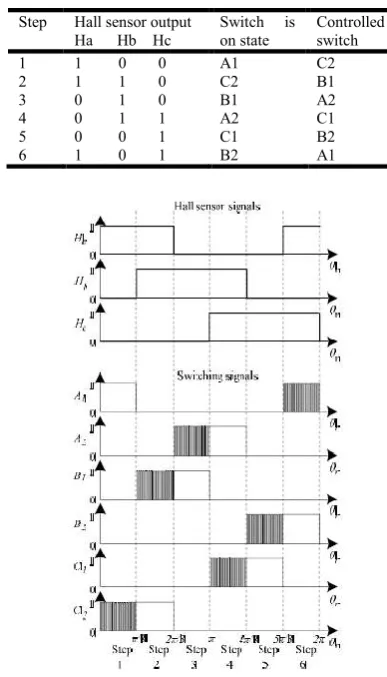
Fig.3.Hall Sensor signals and Switching Signals
Measurement of commutation interval
Fig.4. Step 2 of the switching algorithm: (a) B1 is on; (b) B1 is off
Fig. 5.A buck converter based model of the motor drive
If R is assumed to be small
) ( ) ( 2 )
( et
dt di M L t
V m
in
(5)
)
(
)
(
2
0
e
t
dt
di
M
L
m
(6)
Let the aped of the rotor is ω in rads-1. Then the torque produced by the motor Te (Nm), is given as
t
i
t
e
T
me
(7)
)
(
)
(
t
F
dt
t
d
J
T
T
e
m
(8)
Where J is the combined inertia (kgm2) of the rotor and load and F is the mechanical speed of the motor related by
dt d P
r(9)
Where P is the number of pole pairs of the BLDC motor Time T is the interval for Vin (t) to reach E from 0V and Tm is the period of the input mains voltage.
M
V
E
f
T
sin
12
1
[image:3.595.59.253.224.563.2](10)
Table 1. Switching Algorithm
Step Hall sensor output Ha Hb Hc
Switch is on state
[image:3.595.89.234.611.760.2]Where Vm is the peak value (V) and f is the frequency (Hz) of
the supply.
13
212 2
11 2
3 2 1
T T t t
T t t
T T t t
m m m
[image:4.595.320.544.114.288.2]Fig.6. Controllable and uncontrollable regions of the motor drive at steady state
Fig.7. Proposed technique for torque ripple compensation
Implementation
avg in
DC I
dt t dV
C
(14)
By approximating the derivative, the minimum value of
C
DCthat is required to provide
I
avg from the DC link is given byE V
I T C
in avg DC
2 (15)
To apply the voltage disturbance signal to the system, the commutation duration must be known. To know the commutation duration current sensors have been used. The position senseless controller already uses the terminal voltages for obtaining the ZCP of phase back-EMF. For voltage disturbance signal, if the terminal voltage gives the information related to commutation interval, then the current sensors are not required. When using the out-going phase unipolar PWM scheme, the silent phase terminal voltages remains positive(or zero) dc bus voltage during commutation
and has a different (lower or higher) value than half the dc bus voltage until silent phase back EMF reaches to zero. By measuring the comparator output transition time after starting the commutation, the commutation duration can be known.
Fig. 8. configuration of the experimental BLDC motor drive
Torque ripple, defined as the difference between the least and highest torque divided by the greatest torque, consists of two components: the electromagnetic torque fluctuation and the reluctance torque. Torque ripple in brushless dc motors is mostly due to the fluctuations of the field distribution and the armature MMF which depends on the motor structure and feed current waveform. At high speeds, torque ripple is usually filtered by system inertia. On the other hand at small speeds torque ripple produces noticeable effects that may not be tolerable in applications such as positioning and robotics. An idealized brushless DC motor has a trapezoidal back electromotive force (EMF) waveform. Zero torque ripples is produced for this waveform when the motor is fed by rectangular current. However for practical reasons, non-uniformity of magnetic material and design tradeoffs it is hard to produce the trapezoidal wave shape it a desired manner. Therefore torque ripple appears even though rectangular current is fed in conventional control. In addition, since the motor windings are inductive, the current controller has often no ability to produce the required di/dt in the commutation period due to finite. DC bus supply voltage, the resulting torque ripple is called commutation torque ripple. Torque ripple can create undesirable noise and vibration in speed applications, and can cause inaccuracies in motion control.
SIMULATION RESULTS
[image:4.595.339.532.341.441.2]calculated in the torque controller in normal conduction period and commutation period. Simulation results show that compared with conventional control; there is an apparent reduction in ripple.
Fig.10.Case 3 with M1 for E=65V, (a) Vm(t) and E; (b) Im(t) by theoretical analysis; (c) Im(t) by simulation; and (d) Im(t) by experiment. The motor drive reliability expected to be improved by the removal of DC link capacitor. The periodic torque ripples are predictable by removing the DC link capacitor and the motor drive applicability can be reduced. The compensation capacitor is approximately around 3% of the innovative capacitor. The switching loss of the additional switch is not dominant due to lower switching frequency and current in comparison to the IGBTs in the inverter. So that the total harmonic distortions are reduced and the overall performance of the device is improved due to the absence of the DC link capacitor. As the torque ripple compensation capacitance is low the magnitude s of the capacitor charging currents and transient problems associated are low and hence this method is preferred for compensation and to improve the performance of the drive.
Fig.14. Proposed commutation for case 3: (a) simulated im(t)
without a capacitor and with 150
F
capacitor; (b) simulated) (t
im with proposed compensation; (c) experimentalim(t); and (d)
DC link voltage with proposed compensation
However, the major disadvantage of this proposed method is that the overall motor drive becomes complex. An additional IGBT and driving stage is needed in terms of hardware components.
T 0.94ms
50 2
325 95 sin1
(16)
Fig.15. Torque speed characteristic curve with a 150µF DC link capacitor
The current in IGBT is measured to estimate the loss introduced by the additional IGBT, which is used in compensation circuit.
ON
C I R
P 2
(17)
Appendix: Parameters of The Motor
Parameter Motor M1 Motor M2
R 3Ω 7.5Ω
L-M 15mH 54 mH
J 0.0024 kg-m2 0.0024 kg-m2
F 0.001 Nms 0.001 Nms
P 3 3
Back emf Trapezoidal Trapezoidal
Torque Constant 0.8 NmA-1 1.4 NmA-1
Conventional converter with stiff DC link
Converter without compensation
Converter with compensation THD of the input
Current
203.4% 114.3% 105.6%
Torque ripple due to the absence of the DC link capacitor
0% 100% 8%
Efficiency of the converter
82.3% 81.6% 81.4%
Input THD, torque and Efficiency
Turn ON and turn OFF losses can be found by using turn on and turn off switching energy parameters in the datasheet. The sum of turn on and turn off energies gives the total switching energy.
Switching loss can be calculated by PS ES fS (18)
Where fS is the switching frequency. For the additional switch
the switching frequency is 100Hz for a main supply.
Conclusion
A simple mathematical model and a reparation technique for inherent torque ripples of a BLDC motor drive, operated without a DC link capacitor, have been proposed. The simplicity of the model permits the controller to be implemented on inexpensive microcontroller platforms with very low resources. With the proposed technique for compensating torque ripples, comparable performance to a conventional BLDC motor drive with a large DC link capacitor can be achieved. However, with the torque ripple compensation technique, the overall complexity of the motor drive has been increased, which is a major disadvantage. Based on the application, major augmentations in both hardware and firmware may be required. The good agreement between the theoretical results, simulated results and experimental results demonstrate the accuracy of the simple buck model and the effectiveness of the proposed compensation technique. The proposed compensation technique is expected to be useful for manufacturing low cost BLDC motor drives with comparable performance.
REFERENCES
A Torque Ripple Compensation Technique for a Low Cost Brushless DC Motor Drive.
Berendsen, C.S., Champenois, G., Bolopion, A. 1993. "Commutation strategies for brushless DC motors: influence on instant torque," IEEE Trans. on Power
Electron., vol.8, no.2, pp.231-236, Apr.
Carlson, R., Tavares, A.A., Bastos, J.P., Lajoie-Mazenc, Michel, 1989. "Torque ripple attenuation in permanent magnet synchronous motors,"Industry Applications Society Annual Meeting, 1989., ConferenceRecord of the 1989 IEEE, vol., no., pp.57-62 vol.1, Oct.
Dae-kyong Kim, Kwang-Woon Lee, Byung-Ii Kwon, 2006. "Commutation Torque Ripple Reduction in a Position Sensorless Brushless DC Motor Drive," IEEE Trans. on
Power Electron., vol.21, no.6, pp.1762-1768, Nov.
England, T.R. 1988. "Unique surface-wound brushless servo with improved torque ripple characteristics," IEEE Trans
on Ind. Applications, vol.24, no.6, pp.972-977, Nov/Dec
1988.
England, T.R. 1988. "Unique surface-wound brushless servo with improved torque ripple characteristics," IEEE Trans
on Ind. Applications, vol.24, no.6, pp.972-977, Nov/Dec
1988.
Fang, J., Zhou, X. and Liu, G. 2013. "Precise Accelerated Torque Control for Small Inductance Brushless DC Motor," IEEE Trans. on Power Electron., vol.28, no.3, pp.1400-1412, March.
Fang, J., Zhou, X., and Liu, G. 2012. "Instantaneous Torque Control of Small Inductance Brushless DC Motor," IEEE
Trans. on Power Electron., vol.27, no.12, pp.4952-4964,
Dec.
Gieras, J. F. 2010. Permanent Magnet Motor Technology - Design and Applications: CRC Press.
Haifeng Lu Zhang, Lei Wenlong Qu, 2008. "A New Torque Control Method for Torque Ripple Minimization of BLDC
Motors With Un-Ideal Back EMF," IEEE Trans. on Power
Electron., vol.23, no.2, pp.950-958, Mar.
Jiancheng Fang, Haitao Li and Bangcheng Han, 2012. "Torque Ripple Reduction in BLDC Torque Motor With Nonideal Back EMF," IEEE Trans. on Power Electron., vol.27, no.11, pp.4630-4637, Nov.
Ki-Yong Nam, Woo-Taik Lee, Choon-Man Lee, Jung-Pyo Hong, 2006. "Reducing torque ripple of brushless DC
motor by varying input voltage," IEEE Trans. on
Magnetics, vol.42, no.4, pp.1307-1310, Apr.
Krishnan, R. 2001. Electric Motor Drives, Modeling, Analysis, and Control. Prentice Hall,.[2] R. Krishnan.
Mohamed, Y. AR I., El-Saadany, E.F. 2007. "A Current Control Scheme with an Adaptive Internal Model for
Robust Current Regulation and Torque Ripple
Minimization in PMSM Vector Drive," Electric Machines & Drives Conference, 2007. IEMDC '07. IEEE
International, vol.1, pp.300-305, May.
Ohnuma, Y. and Itoh, J. 2010. "Space vector modulation for a single phase to three phase converter using an active buffer," in Power Electronics Conference (IPEC), 2010
International, pp. 574-580.
Ohnuma, Y. and Itoh, J. I.2009. "Novel control strategy for single-phase to three-phase power converter using an active buffer," in Power Electronics and Applications,. EPE '09.
13th European Conference on, pp. 1-10.
Ozturk, S.B., Alexander, W.C., Toliyat, H.A. 2010. "Direct Torque Control of Four-Switch Brushless DC Motor With
Non-Sinusoidal Back EMF," IEEE Trans. on Power
Electron., vol.25, no.2, pp.263-271, Feb.
Permanent Magnet Synchronous and Brushless DC Motor Drives. CRC Press, 2010.
Samitha Ransara, H. K. and Madawala, U. K. 2011. "A Low Cost Brushless DC Motor Drive," in 6th IEEE Conference on Industrial Electronics and Applications, (IEEE ICIEA), Jun., pp. 2723-2728.
Samitha Ransara, H. K. and Madawala, U. K. 2013. "A technique for torque ripple compensation of a low cost BLDC motor drive," in IEEE International Conference on
Industrial Technology (ICIT), Feb. 2013, pp. 222-227.
Samitha Ransara, H. K. and Madawala, U. K. 2013. "Modelling and Analysis of a Low Cost BLDC Motor," in
IEEE International Conference onIndustrial Technology
(ICIT 2013), Feb., pp. 356-36
Sankaran, F. Rees, and C. Avant, “Electrolytic capacitor life
testing and prediction,” in Industry Applications
Tewari, S.V., Indu Rani, B. 2009. "Torque Ripple Minimization of BLDC Motor with Un-Ideal Back EMF,"
Emerging Trends in Engineering and Technology
(ICETET), 2009 2nd International Conference on, vol., no.,
pp.687-690, Dec.
Yanhui Xu, Parspour, N., Vollmer, U. 2014. "Torque Ripple Minimization Using Online Estimation of the Stator Resistances with Consideration of Magnetic Saturation,"
IEEE Trans. on Ind. Electron., vol.61, no.9, pp.5105-5114,
Sept.
Yongchang Zhang, Jianguo Zhu, Wei Xu, Youguang Guo, 2011.”A simple Method to Reduce Torque Ripple in Direct Torque-Controlled Permanent Magnet Synchronous Motor by Using Vectors with Variable Amplitude and Angle,”
IEEE Trans. On Ind. Electron., vol.58, no.7, pp.2848-2859,
July.