Enhanced Mechanical Properties of Nano/Meso Hybrid Structure Materials
Produced by Hot Roll Sintering Process
Hiroshi Fujiwara, Ryota Akada
*1, Atsushi Noro
*2, Yuki Yoshita
*2and Kei Ameyama
Department of Mechanical Engineering, Faculty of Science and Engineering, Ritsumeikan University, Kusatsu 525-8577, Japan
SUS316L stainless steel and commercially pure titanium powders are processed by Mechanical Milling (MM) which is one of Severe Plastic Deformation (SPD) process. These MM powders are sintered by Hot Roll Sintering (HRS) process. Microstructure of materials produced by HRS process consists of a shell and core hybrid microstructure, that is, a shell structure with nano grains and a core structure with work-hardened coarse grains. All of the HRS materials demonstrate not only superior strength but also good elongation. The mechanical properties are strongly influenced by the shell/core microstructure. The nano/meso hybrid microstructure by HRS process has been proved to be very effective to improve mechanical properties. [doi:10.2320/matertrans.ME200703]
(Received August 1, 2007; Accepted November 2, 2007; Published December 12, 2007)
Keywords: severe plastic deformation, hybrid microstructure, mechanical milling, hot roll sintering, nano grain structure, work-hardened structure, mechanical property
1. Introduction
Grain refinement is well known to influence the mechan-ical properties of materials, especially the strength. One of the promising methods for grain refinement is severe plastic deformation (SPD) process,1,2)such as high pressure torsion (HPT),3) equal channeling angular pressing (ECAP),4,5) accumulative roll bonding (ARB)6)and mechanical milling (MM) or alloying (MA).7–15)The MM treatment at near room temperature, which is one of SPD-powder metallurgy (SPD-PM) process, gives an extremely large deformation compared with other SPD processes in bulk materials mentioned above, and it easily leads to the nano grain structure with the grain size less than 10 nm in diameter.12,13)The materials with a
uniform nano grain structure produced by the SPD processes demonstrate very high strength but have limited ductility because of the plastic instability.16)Whereas, the materials
with a heterogeneous microstructure, which is coarse and fine grain mixture, produced by the SPD-PM process exhibits high strength and advanced plastic strain at the same time.8,11) In this study, sintering by means of hot rolling, i.e., the hot roll sintering (HRS) process, has proposed as a novel sintering method for fabricating a heterogeneous micro-structure material. By this method, a high density compact is able to be fabricated in a short process period. In addition, the HRS process, which is one of the SPD-PM processes, enables one to produce a sintered compact in which the micro-structure has been kept finer even after sintering at the elevated temperature.
The present study demonstrates a relationship between the microstructure and mechanical properties of SUS316L stainless steel and pure titanium powder compacts produced by the HRS process.
2. Experimental Procedure
Mechanical milling of SUS316L powder with average particle size of about 10 or 100mm in diameter was performed for various periods of time by Simoloyer CM01 horizontal ball milling equipment with an SUS304 stainless steel vial and balls in the Ar atmosphere at room temperature. Table 1 indicates chemical composition of the SUS316L powders. HRS was carried out as follows; The MM powders were provided to vacuum-sealing into a mild steel pipe (Fig. 1(a)), then they were hot rolled 5 passes and sintered at 1173 K (Fig. 1(b)). The final reduction in thickness was 90%. Size of the HRS sheet is approximately 20 mm wide and 1.2 mm thick. Some of the HRS materials were annealed at 1073 K, 1173 K or 1273 K for 1.8 ks, 3.6 ks or 7.2 ks. Subsequently, the mild steel pipe was removed from the HRS material, and the HRS materials were examined by means of the optical microscope (OM), scanning electron microscope (SEM), transmission electron microscope/energy dispersive X-ray spectrometer (TEM/EDS) and tensile test. Thin foil for TEM examination was prepared by using an electro-polishing and/or a focused ion beam milling (FIB) method.
In addition, commercially pure Ti powder with average particle size of about 100mmwas also provided to the HRS process. A Fritch P-5 planetary ball mill equipment with tungsten carbide vial and bearing steel balls was used for MM under an Ar atmosphere. Pure titanium pipe was used for vacuum sealing instead of mild steel pipe. The HRS was carried out at 1173 K for the pure Ti powder.
[image:1.595.305.548.344.374.2]Tensile test was performed on SUS316L and Ti HRS material at initial strain rates of 1:7103s1 and
Table 1 Chemical composition of the SUS316L stainless steel powders. (mass%)
C Si Mn P S Ni Cr Mo Fe
0.018 0.90 1.07 0.032 0.017 12.44 17.31 2.11 bal.
*1Graduate Student, Ritsumeikan University. Present address: Aisin Seiki
Co., Ltd., Kariya 448-8650, Japan
*2Graduate Student, Ritsumeikan University. Present address: Kubota
Corporation, Osaka 556-8601, Japan
Materials Transactions, Vol. 49, No. 1 (2008) pp. 90 to 96
Special Issue on Severe Plastic Deformation for Production of Ultrafine Structures and Unusual Mechanical Properties: Investigating Role of High-Density Lattice Defects
8:5104s1, respectively. The specimens have 10 mm gage length, 2 mm width, and 1 mm thickness.
3. Results and Discussion
[image:2.595.55.282.66.424.2]3.1 SUS316L HRS material
Figure 2 indicates a cross sectional SEM image of the SUS316L MM powder milled for 180 ks. There can be seen a dark area in the vicinity of powder surface and a bright area in the middle of MM powder. We named them as ‘‘Shell’’ and ‘‘Core’’, respectively. The width of the shell is approximately 10 to 20mm. The shell thickness depends on the milling time and intensity.8,14,15) Average Vickers hardness of the shell
was Hv:460 and that of the core was Hv:422.
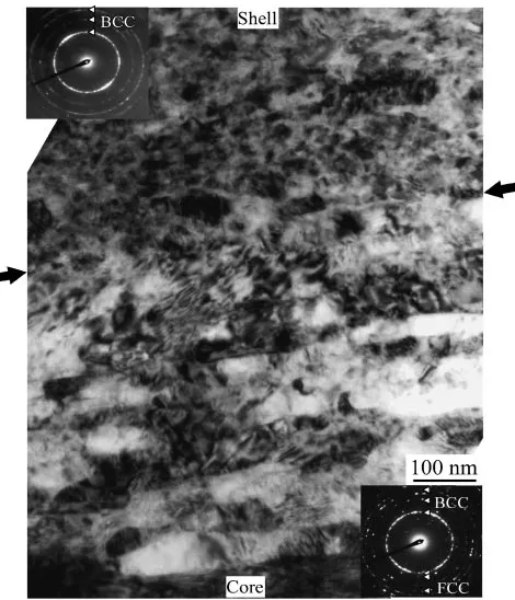
Figure 3 shows a TEM micrograph of shell/core boundary region obtained from the SUS316L MM powder. Selected area diffraction patterns (SADP) from shell and core are also shown in Fig. 3. Upper and bottom side of this figure corresponds to the shell and core area, respectively. Nano grains in the shell area are almost equiaxed and their size is approximately 20 nm in diameter. However, pancake grains laying almost perpendicular to the direction of the powder diameter are observed in the shell/core boundary. In the core area, meso grains as a work-hardened structure can be confirmed. Nano grain structure in the shell transforms to a BCC phase by the grain refinement of SPD process. The mechanism of the FCC to BCC transformation can be
considered as follows. The grain boundary energy of nano austenitic grains is estimated as approximately 1000 J/mol, when the nano austenite grain size is about 20 nm and the austenite interfacial energy is assumed as 0.9 J/m2.15,17)In the austenite to ferrite or martensite phase transformation, 200 to 1000 J/mol is required for the driving force18)so that the nano ferrite grains in the shell presumably formed by the MM process. The shell/core hybrid microstructure formation
Fig. 1 Schematic illustration of the hot roll sintering (HRS) process.
Fig. 2 SEM micrograph of the SUS316L powder mechanically milled for 180 ks. A shell/core structure can be observed. (The powder size is about 100mmin diameter.)
[image:2.595.305.545.74.266.2] [image:2.595.310.545.333.607.2]in the MM powders is able to be controlled by the mechanical milling conditions, such as ball-to-powder weight ratio, powder size, milling time, etc.
Figure 4 shows a 3-dimensional OM image of the SUS316L HRS sheet of the MM powder with average particle size of about 10mm. As shown in the figure, the HRS microstructure composes of two differently etched regions. These dark and bright regions correspond to the shell and core, respectively, and the shell region forms a network
[image:3.595.310.541.70.504.2]structure. The shell network size depends on the powder particle size, i.e., the network size can be controlled by changing the powder particle size. It is noteworthy that the HRS material has a heterogeneous microstructure according to the shell/core microstructure in the MM powder.
Figure 5 shows TEM micrographs of the shell and core regions in the SUS316L HRS material. SADPs from the shell (A) and core (B) region are also demonstrated. TEM observation revealed that microstructure of the shell consists of nano grains and that of the core consists of a coarse meso grains. The grain sizes were several tens nm in the shell and several microns in the core, respectively. Especially in case of the SUS316L HRS material, nano grains in the shell of the MM powder were composed of BCC ferrite nano grains which transformed from FCC austenite to BCC at the MM process as shown in Fig. 3.14,15) During the HRS process, although those ferrite nano grains become austenite () ultra fine grains by the reverse transformation, some of the ferrite nano grains become nucleation sites for sigma () phase.
Fig. 4 OM images of the SUS316L HRS material sheet. A shell (dark) and core (bright) hybrid microstructure is formed. (The powder size is about 10mmin diameter.)
Fig. 5 TEM micrograph and selected area diffraction patterns (SADP) of the SUS316L HRS sheet. A shell/core boundary is shown in white dashed lines. SADP from circle A indicates a (þ) phase formed in the shell and circle B indicates aphase in the core area. (The powder size is about 10mmin diameter.)
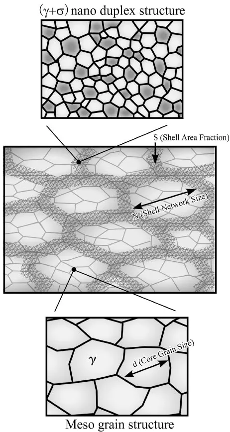
Fig. 6 Schematic illustration of the nano/meso hybrid microstructure in the SUS316L HRS material.
[image:3.595.57.279.71.262.2] [image:3.595.51.291.324.596.2]When the MM powder is annealed at 700 K, partitioning of Cr and Ni elements occurs and Cr-rich nano ferrite grains forms.19)Then, phase precipitates at Cr-rich nano ferrite
when Mo diffusion takes place above 900 K.19) SADP
indicates that a large amount of fineparticles are dispersed in Fig. 5. As illustrated in Fig. 6, the shell region consists of (þ) nano-duplex structure and the core region consists of mesograin structure. Formation of the (þ) nano-duplex structure is a very unique phenomenon even in meta-stable austenitic stainless steels such as SUS316L. As shown in Fig. 6, the control of shell area fraction (S), core grain size (d) and shell network size (N) can form a various nano/meso hybrid microstructure.
Figure 7 shows nominal stress–nominal strain curves of the SUS316L HRS materials with various shell area fraction (S) and core grain size (d). Results of conventional materials
are also indicated. These HRS materials are consolidated from the MM powder of average particle size of about 10mm. ‘‘90%C.R.’’ and ‘‘Bulk’’ indicate results of 90% cold-rolled and solid solution treated bulk specimens, respectively. In HRS materials, the strength increases with increasing shell area fraction (S), and the elongation increases with increasing core grain size (d). Note that the high strength is attributed to the shell area with homogeneously dispersedphase, though it is well known that phase affects mechanical property detrimentally.
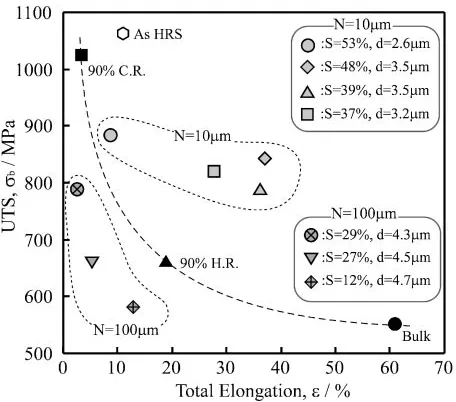
Figure 8 demonstrates results of tensile tests of the SUS316L HRS materials in various conditions, which are shell area fraction (S), core grain size (d) and shell network size (N). The heat treatments were performed to control the microstructure such as shell volume fraction and core grain size. Shell network size depends on the MM powder particle size so that value of N indicates a particle size as shell network size. In the figure, ‘‘90%H.R.’’ indicates a result of 90% hot-rolled bulk specimen. The HRS materials with 10mmnetwork size have both high ultimate tensile strength (UTS) and high elongation. They show enhanced mechanical properties compared to the conventional materials. Whereas, the HRS materials with 100mm of N value have poor mechanical properties compared to the conventional
materi-Fig. 7 Nominal stress-nominal strain curves of the SUS316L HRS materials with various conditions. The results of a conventional SUS316L material with and without cold rolling are also indicated.
Fig. 8 Results of tensile tests of the SUS316L HRS materials before and after heat treatment under various condition.
[image:4.595.53.287.71.273.2] [image:4.595.314.539.72.435.2] [image:4.595.55.283.340.541.2]als. This is probably because density of these HRS materials is not high enough.
Those mechanical properties strongly depend on the microstructure. Strength is attributed to the shell with a nano grain structure, and ductility is attributed to the core with a meso grain structure. In other words, mechanical properties are influenced by microstructure such as shell fraction (S) and core grain size (d).
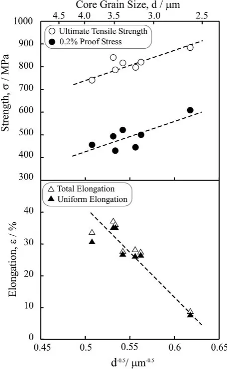
Figures 9 and 10 indicate the strength (UTS and 0.2% proof stress) and elongation (total and uniform elongation) as a function of the shell fraction (S) and inverse of square root of core grain size (d), respectively, in the HRS materials with N value of 10mm. The shell area fraction and core grain size are measured from SEM and TEM micrographs. As shown in Fig. 9, it is obviously that UTS and 0.2% proof stress increases with increasing shell area fraction, while the elongation drops at shell area fraction of approximately 50% or more. These strength and elongation are also strongly influenced by the core grain size, as indicated in Fig. 10. UTS and 0.2% proof stress obey to Hall-Petch relation, that is, the strength increases with decreasing core grain size. However, the elongation decreases with the core grain refinement. Furthermore, the mechanical properties are also strongly
[image:5.595.54.282.73.444.2]influenced by the shell network size which depends on powder particle size as shown in Fig. 8. Finer shell network microstructure indicated superior strength and elongation. In the mechanical property of nano/meso hybrid microstruc-ture, it is very significant that controlling shell fraction (S), network size (N) and core grain size (d).
[image:5.595.301.548.74.288.2]Fig. 10 Relation between strength (UTS and 0.2% proof stress) and elongation (total and uniform elongation) as a function of the core grain size.
[image:5.595.310.540.351.661.2]Fig. 11 SEM micrograph of the pure Ti powder milled for 90 ks. A shell/ core structure can be observed.
Fig. 12 TEM micrograph of a shell/core boundary region in the pure Ti powder milled for 90 ks. Arrows indicate a shell/core boundary.
3.2 Pure titanium HRS material
The microstructural features of the HRS materials were observed not only in the SUS316L HRS material but also in a pure Ti HRS material.
Figure 11 shows SEM micrograph of the cross section in the pure Ti powder milled for 90 ks. This powder consists of two regions,i.e., shell and core. The shell, approximately 10 to 20mmwide, has a severe plastic deformed structure and the core has a conventional work hardened structure. Figure 12 demonstrates a TEM micrograph of the shell area of the pure Ti powder milled for 90 ks. In Fig. 12, equiaxed nano grain structure with approximately 50 to 100 nm in diameter is observed between from the powder surface to about 10mm. Elongated grain structure with the wide of approximately 100 nm is seen in about more than 10mm. In the nano grain refinement of pure Ti material, the nano grain is formed from the nano layered structure.13–15) Figure 12
reveals that the shell as shown in Fig. 11 consists of nano grain structure. From Figs. 11 and 12, it is shown that the Ti MM powder has shell and core structure with nano and meso grain structure, respectively. Such a MM powder with nano grain structure in the shell is consolidated by the HRS process.
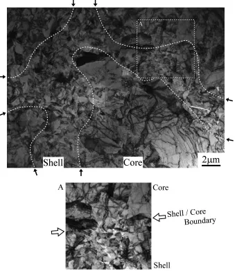
Figure 13 shows a TEM micrograph of a part of the shell/ core hybrid microstructure in the pure Ti HRS material. The TEM thin foil was prepared by FIB method. A white dashed line indicates a boundary of the shell and core area. The shell area has an ultra fine grain with about 200 to 500 nm in diameter. Such a shell region is formed in surroundings of the core region with the meso grain structure. The pure Ti HRS material has the nano/meso hybrid microstructure as well as the SUS316L HRS material.
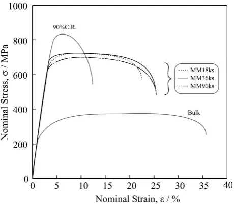
Figure 14 demonstrates nominal stress–nominal strain curves of pure Ti HRS materials with various MM condition. The HRS materials at each MM time demonstrate enhanced mechanical properties compared to the conventional pure Ti materials, marked as ‘‘Bulk’’ and ‘‘90%C.R.’’. Superior mechanical properties are decided by the hybrid micro-structure with the two regions of nano and meso grain structure. The strength of MM 90 ks is lower than that of MM 36 ks shown in Fig. 14. This result reveals that the strength does not depend on only the milling time because the hybrid microstructure is a complex structure. The MM and HRS process are also very effective for improving mechanical properties of Ti material.
[image:6.595.130.469.76.467.2]As mentioned above, enhanced mechanical properties are
obtained in both SUS316L and pure Ti materials produced by MM/HRS process. Such superior mechanical properties are attributed to the nano/meso hybrid microstructure, which constitute a shell area with nano grain structure and a core area with meso grain structure. For instance, Oh-ishi et al.
reported that a bimodal structure consisting of fine and coarse grained region demonstrated high strength and high plastic strain in Fe-C alloy.11) Therefore, it is possible that other metal materials with the nano/meso hybrid structure also indicate enhanced mechanical properties.
4. Conclusion
Mechanically milled SUS316L stainless steel and pure titanium powders were sintered by the hot roll sintering (HRS) process, which is one of the SPD-PM processes. The conclusions are as follows;
(1) The materials fabricated by the HRS process consist of a shell and core hybrid microstructure, that is, a shell structure with nano grains and a core structure with coarse meso grains.
(2) In the SUS316L HRS material, shell area is composed of an (austenite + sigma) nano duplex structure for a specific phase transformation occurred by the SPD-PM process, and core area is composed of meso austenite grain structure. In the pure Ti HRS material, shell and core area are composed of nano grain and meso grain
structure, respectively.
(3) The shell region takes charge of high strength and the core region takes charge of high ductility. Thus, mechanical properties of the HRS materials are strongly influenced by microstructure such as the shell area fraction and the core grain size.
(4) The HRS materials demonstrate not only superior strength but also enough elongation. The shell and core nano/meso hybrid microstructure created by the HRS process has been proved to be very effective to improve the mechanical properties.
Acknowledgement
This study was supported by a Grant-in-Aid for Scientific Research from the Ministry of Education, Culture, Sports, Science and Technology (MEXT), Japan on Priority Areas ‘‘Giant Straining Process for Advanced Materials Containing Ultra-High Density Lattice Defects’’.
REFERENCES
1) R. Z. Valiev, R. K. Islamgaliev and I. V. Alexandrov: Prog. Mater. Sci. 45(2000) 103–189.
2) I. V. Alexandrov and R. Z. Valiev: Scripta Mater.44(2001) 1605– 1608.
3) Z. Horita, D. J. Smith, M. Furukawa, M. Nemoto, R. Z. Valiev and T. G. Langdon: J. Mater. Res.11(1996) 1880–1890.
4) V. M. Segal: Mater. Sci. Eng., A197(1995) 157–164.
5) Z. Horita, M. Furukawa, T. G. Langdon and M. Nemoto: Materia Jpn. 37(1998) 767–774.
6) Y. Saito, N. Tsuji, H. Utsunomiya, T. Sakai and R. G. Hong: Scripta Mater.39(1998) 1221–1227.
7) J. S. C. Jang and C. C. Koch: Scripta Met. Mater.24(1990) 1599–1604. 8) H. Fujiwara, R. Akada, Y. Yoshita and K. Ameyama: Mater. Sci.
Forum503–504(2006) 227–232.
9) H. W. Zhang, R. Gopalan, T. Mukai and K. Hono: Scrpta Mater.53 (2005) 863–868.
10) H. W. Zhang, R. Gopalan, T. Mukai and K. Hono: Scrpta Mater.54 (2006) 1827–1828.
11) K. Oh-ishi, H. W. Zhang, T. Ohkubo and K. Hono: Mater. Sci. Eng., A 456(2007) 20–27.
12) S. Ohsaki, K. Hono, H. Hidaka and S. Takaki: Scripta Mater.52(2005) 271–276.
13) M. Umemoto: Mater. Trans.44(2003) 1900–1911.
14) H. Fujiwara, H. Inomoto, R. Sanada and K. Ameyama: Scripta Mater. 44(2001) 2039–2042.
15) H. Fujiwara, H. Inomoto and K. Ameyama: Tetsu-to-Hagane91(2005) 839–845.
16) E. Ma: Scripta Mater.49(2003) 663–668. 17) T. A. Roth: Mater. Sci. Eng.18(1975) 183–192. 18) T. Maki: Tetsu-to-Hagane81(1995) N547–N555.
[image:7.595.54.284.71.272.2]19) K. Ameyama, M. Hiromitsu and N. Imai: Tetsu-to-Hagane84(1998) 357–362.
Fig. 14 Nominal stress-nominal strain curves of the pure Ti HRS materials with various milling conditions. The results of a conventional Ti material with and without cold rolling are also indicated.