Development of New T-Bar Production Technology by Tandem Universal Rolling
*1Yukio Takashima
1,*2, Yoichiro Yamaguchi
2, Hideki Takahashi
3, Tomoo Horita
3and Toshio Nakatsuka
3,*3 1Steel Research Laboratory, JFE Steel Corporation, Kurashiki 712–8511, Japan2West Japan Works (Fukuyama), JFE Steel Corporation, Fukuyama 721–8510 Japan
3Construction Materials & Services Business Division, JFE Steel Corporation, Tokyo 100–0011, Japan
Application of T-bars in shipbuilding has increased recently. Slim T-bars having a web height of at least twice the flange width are gen-erally required in ships. Because the dimensions of existing hot-rolled T-bars are unsuitable, T-bars fabricated by welding two plates are cur-rently used in shipbuilding. To manufacture slim T-bars by hot rolling, we devised a new T-bar rolling process using two universal mills and an edging mill. The two universal mills have different roll shapes. The horizontal roll width of the first mill is wider than the web height of the T-bar, whereas that of the second mill is narrower than the web height in order to reduce the web height with a vertical roll. Multi-pass rolling experiments with pure lead were performed using the new process, and a T-bar having an excellent cross section was obtained. Finite element analyses of universal rolling were also carried out to investigate the rolling deformation behavior in this process in detail. Following these in-vestigations, a T-bar hot rolling test was carried out at an actual structural steel mill. As a result, steel T-bars with an excellent cross section were successfully produced, and the capability of the new T-bar rolling technology was clearly demonstrated.
[doi:10.2320/matertrans.P-M2017830]
(Received March 24, 2017; Accepted July 21, 2017; Published September 1, 2017)
Keywords: section rolling, laboratory model rolling experiments, finite element analysis, rolling deformation, mill trial
1. Introduction
Several section steel products are used for ships in order to increase the hull stiffness. For example, unequal-leg an-gles, unequal-leg angles with different leg thicknesses and bulb-plates are used in shipbuilding, and these sections are manufactured by hot rolling. To achieve higher hull stiff-ness, sections having a height of at least twice the width are generally required for ships, and a wide variation of heights, widths and thicknesses are required for reduction of ship structural weight1).
Application of T-bars in shipbuilding has increased re-cently2). However, hot rolling of T-bars for ships has not
been realized, as it is difficult to produce slim sections suit-able for ships by conventional T-bar rolling methods such as groove rolling3) and three-roll rolling4,5). As a result, T-bars
for ships are typically fabricated by welding two plates. The authors have carried out research on new T-bar ing technologies employing universal mills. Universal roll-ing technology is widely applied to the manufacture of H-beams, and universal rolling facilities have been intro-duced at many structural steel mills. Moreover, because the roll gaps of the horizontal and vertical rolls can be set indi-vidually in a universal mill, it is possible to produce prod-ucts with several different thicknesses with the same rolls. This T-bar rolling technology was first proposed in a Japanese patent6), but was not examined as a practical
pro-cess for many years, probably due to the large asymmetry of the rolled section geometry, which was expected to cause large side camber in rolling.
However, it was reported that slim T-bars could be rolled by determining the appropriate thickness reductions of the web and flange for side camber control. In addition, the
fluence of rolling conditions on deformation behavior, in-cluding flange spread, was presented7). An extended T-bar
rolling technology with a universal mill and an edger mill was investigated by numerical simulation and laboratory rolling experiments, and the possibility of manufacturing T-bar products with suitable cross sections for ships with normal universal rolling facilities for H-beam production was demonstrated8). Although that work revealed the
prob-lem of larger web height around the top and tail ends of the rolled T-bars in comparison with other parts, this problem was solved by introducing additional vertical rolls in the edger mill. A laboratory model rolling experiment with the new edger roll arrangement was carried out and a pure lead T-bar having a constant web height over its entire length was obtained8).
Based on these previous studies, in the present research, we investigated a practical T-bar rolling technology by versal rolling. An actual structural steel mill with two uni-versal mills and a normal edger mill was selected for the mill layout in this research, and a new high productivity tan-dem universal rolling method was invented by applying this mill layout. A series of laboratory model rolling experiments was carried out to examine the potential of this rolling method. In addition, rolling deformation in universal rolling with a new roll arrangement was investigated by finite ele-ment analysis (FEA), and mill trials were carried out at an actual structural steel mill to verify the possibility of T-bar production with the tandem universal rolling technology.
2. Outline of T-bar Tandem Universal Rolling
Past research demonstrated the possibility of T-bar univer-sal rolling with the mill layout shown in Fig. 1. In the inter-mediate rolling step, a universal mill (UR) reduces the thick-nesses of the web and flange, and an edger mill (E) with vertical rolls reduces the tips of the web and flange. Because the configuration of the edger mill with additional vertical rolls is similar to a universal mill, two universal mills are
*1 This Paper was Originally Published in Japanese in J. JSTP. 58 (2017)
53–59.
*2 Corresponding author, E-mail: [email protected] *3 Present address: JFE Bars & Shapes Co., Tokyo 105–0004, Japan
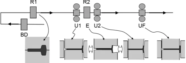
needed in this method as an intermediate rolling facility. Figure 2 shows another mill layout which actually exists and was selected for this research. Two 2Hi rolling mills (BD, R1) are used to form the initial steel material to an ade-quate section shape for the target products. In H-beam pro-duction, the cross sections of the reheated materials are formed by groove rolling to a thick H shape. The intermedi-ate rolling facility, R2, consists of two universal mills (U1, U2) and a normal edger mill (E) between the universal mills. Reverse rolling is performed with these three rolling mills. Finally, a finishing universal mill (UF) is used for 1 pass rolling to form the T-bar to the product section shape.
In order to produce T-bars by using the intermediate roll-ing facility in Fig. 2, the new tandem universal rollroll-ing method in Fig. 3 was invented. The roll arrangements of U1 and E are the same as the initial ones reported in the previ-ous research8), and U1 reduces the thickness while E
con-trols the flange width. Another universal mill (U2) was newly introduced in the intermediate facility. Its horizontal roll width is smaller than the web height of the rolled T-bar, and the web thickness, except around the web tip, is reduced by the horizontal rolls. One vertical roll of U2 reduces the flange thickness, and the other vertical roll reduces the web height through contact with the web tip. Because the U2 mill reduces the web and flange thicknesses while controlling the
web height, it is possible to reduce the pass numbers in re-verse intermediate rolling.
On the other hand, because the web thickness around the web tip is not reduced in U2, this is expected to cause a thickness difference in the web. Although this was consid-ered to be a drawback of this roll arrangement, it was also expected to be possible to eliminate this thickness difference in the following passes in U1 or UF and obtain a uniform web thickness in the final T-bar products.
First, a series of model rolling experiments was carried out in order to examine the change of the web thickness in the section and the uniformity of the web height along the length after tandem universal rolling.
3. Laboratory Experiments
3.1 Experimental apparatus
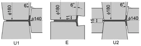
A constant reduced-scale of one-fifth was assumed in the experiments. Two laboratory universal mills and a laboratory 2Hi mill were prepared, and the rolls shown in Fig. 4 were used in the experiment. The diameters of the horizontal and vertical rolls in the universal mills were 180 and 140 mm, respectively. The side surfaces of the horizontal rolls and the outer surfaces of the vertical rolls have an inclination of 6 . The edger rolls have a groove for flange width reduction cor-responding to the cross section of the rolled T-bar. The max-imum diameter of the edger rolls was 180 mm, and the same inclination of 6 was also applied to the groove part. A pair of upper and lower guides for the web and flange inside sur-faces was introduced with vertical side guides at the entry and exit sides of the universal and edger rolls8).
3.2 Experimental conditions
Pure lead (99.99%) was used as the model material of the experiment. Pure lead has deformation behavior similar to that of hot carbon steel at elevated temperatures9). The actual
product size of the web height of 300 mm and flange width of 125 mm (T300 × 125) was selected for the experiment. The names and symbols of the dimensions in the T-bar cross section are shown in Fig. 5. Intermediate rolling with the
Fig. 2 Mill layout of newly-developed T-bar tandem universal rolling process.
Fig. 3 Schematic of T-bar tandem universal rolling process.
Fig. 4 Dimensions of rolls in model experiments.
[image:2.595.62.277.398.497.2] [image:2.595.47.290.540.597.2] [image:2.595.304.549.572.653.2] [image:2.595.62.275.648.773.2] [image:2.595.344.509.693.771.2]universal mills and an edger mill was examined in the experiment.
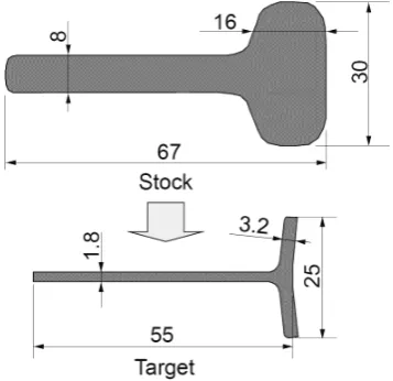
The cross sections of the initial stock and the target after intermediate rolling are shown in Fig. 6. Because of the short web height of the prepared initial stock, the target web height after rolling was set to 55 mm, which was smaller than one-fifth of assumed product web height.
Table 1 shows the draft schedule of the rolling experi-ment. The order of the rolling mills was determined to simu-late a 5 pass series of tandem reverse rolling. Therefore, the order of the two universal mills was opposite in the odd and even pass numbers. The target thicknesses in the universal rolling passes were determined so as to keep constant thick-ness reductions. The web thickthick-ness reduction was 15% and the flange thickness reduction was 18%, with the exception of the 5th pass at U2, where the thickness reduction was set to 1%. In the universal rolling passes after edger rolling, the flange thickness was adjusted in consideration of the flange thickness increase in the former edger rolling. The position
of the U2 vertical roll for web height reduction was deter-mined based on the measured web height before the pass so as to obtain the appropriate reduction of web height. The roll gap of edger rolling was set to be 0.2 mm larger than the web thickness to prevent web thickness reduction in edger rolling.
3.3 Results of experiment
Cross sections of the pure lead T-bars obtained in the roll-ing experiment are shown in Fig. 7. Although there is an ob-vious thickness difference in the web in the cross section af-ter the 1st pass, the cross section afaf-ter the 2nd pass afaf-ter rolling with U1 has a uniform web thickness. In addition, no surface defects were observed around the position of the thickness difference. The thickness difference of the web was small after the 3rd pass, and the rolling experiment was completed without problems.
The web tip was rolled from the 1st pass, and the cross section of the web tip was formed to an almost square shape after the 5th pass. The flange width reduction in edger roll-ing also satisfied the target dimension in each pass.
Flange side camber in universal rolling occurred in the be-ginning of the rolling process, and web side camber oc-curred in edger rolling. These side cambers were restricted by the guides and did not disturb the rolling operation in the following pass.
Figure 8 shows the dimensions of the final cross section as measured with a micrometer and caliper. The dimensions in the cross section substantially satisfied the target values.
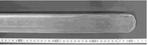
The appearance of the top end of the rolled pure lead T-bar is shown in Fig. 9. This photograph was taken from
[image:3.595.79.258.323.496.2]Fig. 6 Sections of initial stock and target after intermediate rolling.
Table 1 Draft schedule of experiment. Pass No. Web thickness
(mm)
Flange thickness (mm)
Flange width (mm)
Stock 8.00 16.00 30.0
1 U1 7.20 14.40
E 29.4
U2 6.05 12.10
2 U2 5.14 9.92
E 27.3
U1 4.32 8.33
3 U1 3.67 6.83
E 25.9
U2 3.08 5.74
4 U2 2.62 4.71
E 24.8
U1 2.20 3.95
5 U1 1.87 3.24
E 24.1
[image:3.595.357.496.470.769.2] [image:3.595.49.291.558.788.2]the front of the web surface. The flange is located upward, while the web tip is located downward. The web tip was straight, and a constant web height was achieved over the whole length.
The results of this experiment demonstrated that T-bars with a constant web height and the target cross section can be produced by the tandem universal rolling method. In or-der to investigate the rolling deformation in U2 in detail, a series of 3D FEA was performed.
4. Finite Element Analysis of Universal Rolling
4.1 Finite element model
In order to investigate the difference of rolling deforma-tion without and with web height reducdeforma-tion (U1 and U2), FE analyses of universal rolling with these two roll arrange-ments were performed. For the case with web height reduc-tion, several web height reductions were simulated in order to study the influence on rolling deformation. A series of elasto-plastic analyses was carried out with Abaqus Explicit ver.6.12, and a non-steady-state simulation was performed starting with the entry of the top end of the T-bar into the roll gap. Because of the symmetric cross section of the T-bar, a half model was constructed. The initial cross section of the T-bar for the FEA is shown in Fig. 10. The initial length of the T-bar was 1500 mm, and solid brick reduced integration elements (C3D8R) were used for the T-bar. The element number was 485 in the cross section and 375 in the length. The total number of the elements in the half T-bar was approximately 180,000.
The roll geometries and dimensions are shown in Fig. 11. Guides supporting the flange inside and web surfaces, as
shown by the dash lines in Fig. 11, were placed at the entry side of the rolls. A flat vertical guide was also set at the outer side of the flange to restrict the flange side camber of the rolled T-bar at the entry and exit of the rolls. The rolls and the guides were assumed to be analytical rigid surfaces. The horizontal rolls were driven at 40 rpm, and the vertical rolls were defined as undriven and freely rotating parts. The guides were fixed at their initial positions.
4.2 Numerical conditions
A list of the numerical conditions of the FEA is given in Table 2. A fundamental universal rolling condition, a web thickness reduction of 15% and flange thickness reduction of 18%, was set by adjusting the positions of each roll. A Coulomb friction model was applied between the workpiece and the rolls, and the friction coefficient was 0.4. The fric-tion coefficient between the workpiece and guides was set to zero.
A flow stress curve for hot carbon steel proposed by Misaka and Yoshimoto10) was used for the workpiece. In the
FEA, a uniform temperature of 1000 C was assumed in the workpiece, and the carbon content was set to 0.15%. From the temperature and carbon content, the flow stress of the workpiece is expressed by the following eq. (1).
k f =113.2·ε0.21·ε˙0.13 (1) Where, kf is flow stress (N/mm2), ε is plastic strain and ε˙
is the plastic strain rate. The flow stress data for the analysis were prepared based on eq. (1). The Young s modulus and Poison ratio of the workpiece were 100,000 N/mm2 and 0.3,
respectively. A mass scaling factor of 100 was used in the dynamic explicit analysis.
[image:4.595.100.240.484.556.2]A simulation of U1 was executed under these numerical conditions, and the same numerical conditions were also ap-plied in the U2 rolling simulation. In addition, the base posi-tion of the web tip side vertical roll where the vertical roll had no contact with the web tip was firstly defined, and the
Table 2 Numerical conditions of FEA.
Horizontal roll rotation speed 40 rpm (4.19 rad/s) Target web thickness reduction 15% Target flange thickness reduction 18% Friction coefficient (workpiece and roll) 0.4
(workpiece and guide) 0.0 Young s modulus of workpiece 100,000 N/mm2
Poisson ratio of workpiece 0.3
Fig. 8 Dimensions of cross section of rolled workpiece after 5th pass.
[image:4.595.314.539.545.639.2]Fig. 9 Appearance of top end of rolled pure lead T-bar.
Fig. 10 Cross section of half T-bar for FEA.
[image:4.595.48.291.602.676.2] [image:4.595.303.550.695.788.2] [image:4.595.89.246.715.771.2]first U2 rolling simulation was executed. The vertical roll position was then changed toward the horizontal rolls by 5, 10 and 15 mm, and U2 rolling simulations with web height reduction were executed at each of these vertical roll posi-tions. In total, four different simulations were executed for the U2 rolling investigation.
4.3 Results of FEA
An example of the rolling deformation in a FEA is shown in Fig. 12. There was a vertical guide at the outside of the flange (not shown in Fig. 12), and that guide restricted the flange side camber in the analyses. All universal rolling sim-ulations were completed without problems over the entire length of the T-bar.
The cross sections at the center of the workpiece length obtained by the FEA were compared in order to investigate the influence of the roll geometry and web height reduction on rolling deformation. The cross sections after U1 rolling and U2 rolling without web height reduction (base position of the vertical roll) are shown in Fig. 13. Here, it can be ob-served that the web height of the workpiece rolled in U2 is smaller than that of the workpiece rolled in U1. The web tip thickness after U2 rolling was 18.32 mm which is thicker than the web part rolled with horizontal rolls, but this be-came thinner than the initial web thickness of 20 mm. It was supposed that the web tip without thickness reduction was elongated together with the elongation of the T-bar by roll-ing, and this web tip elongation caused the decrease of web height and web tip thickness. In addition, the position of the flange top was slightly downward, and the flange width after U2 rolling became smaller than that after U1 rolling by 0.38 mm.
Four cross sections after U2 rolling with the vertical roll
positions of base (no reduction), 5, 10 and 15 mm are com-pared in Fig. 14. The web tip thickness increased with larger web height reduction. However, as the border between the rolled and free surfaces was not steep, occurrence of harmful surface defects in the following uniform web thickness roll-ing in U1 was considered minimal. The flange width de-creased with the increase of web height reduction. The dif-ferences of the web height under the condition of no web height reduction and the other conditions were defined as the web height reduction, and the influence of the web height re-duction on the web tip thickness and flange width were investigated.
The relationship between the web tip reduction and web tip thickness is shown in Fig. 15. The inclination of the graph becomes steeper with larger web height reduction. Because a larger web tip thickness increases the risk of sur-face defects in U1 rolling, the minimum web tip reduction necessary to obtain a flat web tip and constant web height over the entire length is considered to be an appropriate U2 rolling condition.
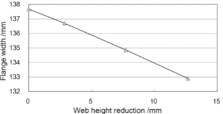
[image:5.595.316.540.367.453.2]The relationship between the web height reduction and flange width after rolling is shown in Fig. 16. The flange width after U2 rolling decreased linearly against the web
[image:5.595.76.261.493.640.2]Fig. 12 Example of deformation and strain in FEA (U2, web tip side ver-tical roll position 10 mm).
[image:5.595.316.539.501.616.2]Fig. 13 Cross sections of workpiece rolled by U1 and U2 rolling without web height reduction.
[image:5.595.316.540.655.770.2]Fig. 14 Cross sections of workpiece rolled by U2 rolling with different web height reductions.
Fig. 15 Influence of web height reduction on web tip thickness.
[image:5.595.56.282.693.763.2]height reduction. Due to the web height reduction, the defor-mation in the length direction around the web tip increased, and the web elongation became larger. In turn, the larger web elongation increased flange elongation, and flange spread decreased. If the decrease of flange width becomes excessive, an insufficient product flange width is possible. Therefore, it was also concluded that an excessively large web height reduction should be avoided in the U2 rolling.
5. Mill Trial of T-bar Tandem Universal Rolling
5.1 Mill trial facilities and rolling conditions
Based on the laboratory experiment with the new tandem universal rolling method, in which a pure lead T-bar was successfully manufactured, mill trials were conducted at an actual structural steel mill. A series of T-bar rolling tests with T300 × 125 was arranged at the Large Shape Mill at West Japan Works (Fukuyama) of JFE Steel Corporation. The layout of the shape mill and the schematic of the ap-plied rolling method are shown in Fig. 17. The 2Hi rolling mills, BD and R1, have several grooves and form a thick T-bar similar to the stock shape in Fig. 6. Although the roll shapes of intermediate and finishing rolling were similar to those in the laboratory experiment, as shown in Fig. 4, slight modifications were introduced for better rolling operation. For example, the web tip side vertical rolls were changed to a cylindrical type, and the side surface of the horizontal rolls facing the cylindrical vertical rolls was modified to a vertical angle. These alterations of the roll shape were made to en-able easier setting of the original position of the rolls.
As in the laboratory experiment, the pass number of inter-mediate reverse rolling was five. The draft schedule of the mill trial was basically prepared based on the experiment, but larger thickness reduction was given in the earlier uni-versal rolling passes in consideration of the rolling tempera-ture. Following the output of the experiment and FEA, the web height reduction in U2 was set to be as small as possi-ble in the range for preventing web height expansion around the top and tail ends. However, as the optimum web height reduction is influenced by the web height spread in universal rolling, the position of the web tip side vertical roll was ad-justed based on the cross sectional dimensions of the rolled T-bar.
Because the intermediate rolling process was tandem roll-ing with three stands, bucklroll-ing of the rolled T-bar and result-ing rollresult-ing problems due to the compressive force between the stands were considered possible. In order to avoid these
problems, the horizontal roll rotation speeds of the mills were determined so as to cause tensile force between all stands.
The number of finishing universal rolling passes was one, and straightening of the flange inclination was carried out in this pass, as well as slight thickness reductions to obtain uni-form thicknesses in the web and flange.
5.2 Results of mill trial
First, the target product thicknesses of the web and flange were set to 10 and 19 mm, respectively. Although several problems occurred at the beginning, T-bar products with the target cross section were manufactured successfully. At the same time, side camber of the T-bar in rolling operation was restricted within an adequate range by application of the guides and selection of appropriate rolling conditions. An example of UF rolling observed from the exit side is shown in Fig. 18. The rolled T-bar was straight from the top end. Because the web was thinner than the flange, the web tem-perature was lower than the flange temtem-perature after finish-ing rollfinish-ing, and this temperature difference caused flange side camber after cooling to room temperature. Straightening of the T-bar was carried out at room tempera-ture to eliminate this side camber.
The appearance of a T-bar product is shown in Fig. 19. T-bar products with good cross-sectional uniformity over the entire length were obtained in the mill trial.
[image:6.595.349.504.475.615.2]A cross section of a T-bar is shown in Fig. 20. The dimen-sions in the cross section, including the thicknesses, satisfied the tolerances provided in the applicable Japanese Industrial Standard, and the web tip was flat and square as a result of rolling with the web tip side vertical roll in U2.
[image:6.595.134.462.657.769.2]Fig. 17 Mill layout and roll shape used in T-bar tandem universal rolling test.
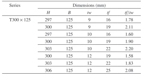
A feature of universal rolling is the individual setting of the horizontal and vertical rolls, which enables production of products with different thicknesses with the same pair of rolls. Therefore, in this mill trial, the common use of rolls to produce T-bars with different thicknesses was examined. The web thickness of the stock before intermediate rolling was controlled by changing the roll gaps of the BD and R1 mills, and tandem and finishing universal rolling were per-formed with appropriate draft schedules for each product. As a result, several T-bar products with the different thicknesses shown in Table 3 were manufactured with the same pair of rolls, successfully confirming the merit of common use of rolls by universal rolling. The variation of tf/tw shown in Table 3 corresponds to the possible roll gap range of the BD and R1 grooved rolls. If the roll design of these rolling mills is improved for larger roll gap control, it is expected to be possible to expand the tf/tw range of products.
The results of the mill trial demonstrated that the new tan-dem universal rolling method can manufacture T-bars suit-able for ships with high productivity. Considering the high efficiency of this process and the variety of product thick-nesses, this new tandem rolling technology is expected to make a great contribution to T-bar production for ships.
6. Conclusion
A new T-bar tandem rolling technology which uses two
universal mills and an edger mill was invented, and its feasi-bility and rolling deformation behavior were evaluated by laboratory rolling experiments and FEA. In order to validate the T-bar rolling technology, mill trials were also carried out at an actual structural steel mill. The following conclusions were obtained as a result of this study:
(1) Although the new universal rolling method with no web thickness reduction around the web tip caused a thick-ness difference in the web, the thickthick-ness difference could be eliminated without surface defects in the fol-lowing pass by using other universal mill, in which the whole web received thickness reduction.
(2) The web height reduction with the new universal mill formed a flat web tip, and the web height became uni-form along the whole length of the T-bar.
(3) When the web tip did not receive thickness reduction, the web height after rolling became smaller than that with whole web thickness reduction.
(4) As the web height reduction with the vertical roll in-creased, the web tip thickness increased while the flange width decreased.
(5) In mill trials at an actual structural steel mill, the feasi-bility of the new tandem universal rolling technology was clearly demonstrated by the successful production of T-bars with the target dimensions.
REFERENCES
1) Kouzai-Kurabu: Shipbuilding and Steel, (Kouzai-Kurabu, Tokyo, 1993) pp. 51–55.
2) P.A. Blomquist, N. Orozco and D. Patch: J. Ship Production. 20 (2004) 114–121.
3) E. E. Brayshaw: Rolls and Rolling, (Blaw-Knox Company, Pennsylvania, 1958) pp. 260–275.
4) I. Kyoi, K. Nakajima, K. Isozumi, K. Kishikawa and K. Watanabe: Proc. 29th Joint Conf. of the JSTP, (The JSTP, 1978) pp. 118–120. 5) I. Nakauchi and T. Hirasawa: Tetsu-to-Hagané. 73–12 (1987) 376. 6) S. Hirayo, I. Noda, M. Awano, Y. Yamamoto, T. Ueda, H. Minami, R.
Hirano, F. Someno and S. Inoue: Japanese Patent, (1968) Examined Publication Number 1968–19671.
7) Y. Takashima and T. Hiruta: ISIJ Int. 52 (2012) 1328–1334.
8) Y. Takashima and N. Nakata: J. Mater. Process. Technol. 229 (2016) 149–159.
9) K. Nakajima: Shape Rolling Technology of Steel, (Chijin Shokan Co., Ltd., Tokyo, 1999) pp. 212–214.
[image:7.595.109.230.69.294.2]10) K. Misaka and T. Yoshimoto: J. Jpn. Soc. Technol. Plast 8 (1967) 414–422.
Table 3 Dimensions of T-bar products.
Series Dimensions (mm)
H B tw tf tf/tw
T300 × 125 297 125 9 16 1.78
300 125 9 19 2.11
297 125 10 16 1.60
300 125 10 19 1.90
303 125 10 22 2.20
300 125 12 19 1.58
303 125 12 22 1.83
[image:7.595.301.549.83.213.2]306 125 12 25 2.08
[image:7.595.72.267.332.426.2]Fig. 19 Example of rolled T-bar.