https://doi.org/10.1007/s10035-018-0795-0 ORIGINAL PAPER
Discrete element modelling of under sleeper pads using a box test
Huiqi Li1 ·Glenn R. McDowell1
Received: 29 July 2017 © The Author(s) 2018
Abstract
It has recently been reported that under sleeper pads (USPs) could improve ballasted rail track by decreasing the sleeper settlement and reducing particle breakage. In order to find out what happens at the particle–pad interface, discrete element modelling (DEM) is used to provide micro mechanical insight. The same positive effects of USP are found in the DEM simulations. The evidence provided by DEM shows that application of a USP allows more particles to be in contact with the pad, and causes these particles to transfer a larger lateral load to the adjacent ballast but a smaller vertical load beneath the sleeper. This could be used to explain why the USP helps to reduce the track settlement. In terms of particle breakage, it is found that most breakage occurs at the particle–sleeper interface and along the main contact force chains between particles under the sleeper. The use of USPs could effectively reduce particle abrasion that occurs in both of these regions.
Keywords DEM·Railway ballast·Under sleeper pad
1 Introduction
In recent years, under sleeper pads (USPs) have become popular in newly-built high speed railway tracks in central Europe. USPs are resilient pads installed at the bottom sur-faces of sleepers to provide an intermediate elastic layer between the ballast and the sleeper with the intention of improving sleeper–ballast interaction or for mitigating ground borne noise and vibration. Figure 1 shows a pic-ture of a typical ballasted railway track with USPs. USPs normally have a thickness of about 10 mm and are made of polyurethane elastomer with a foam structure including encapsulated air voids [1].
A number of field and laboratory tests have been carried out to investigate the influence of USPs, mostly reporting pos-itive results, a summary of which will now be given. From field experience, Bolmsvik [2] showed that track misalign-ment could be reduced by the use of USPs. USPs have also been found to reduce both inter-particle abrasion and sleeper– ballast attrition [3,4]. Both Riessberger [5] and Abadi et al. [6] observed that the use of a USP increases the ballast– sleeper contact area which leads to a reduced contact pressure in experimental tests. This was presumed to be the reason
B
Huiqi Li1 Nottingham Centre for Geomechanics, University of
Nottingham, Nottingham, UK
why USPs help to reduce ballast damage [3]. Lakuši´c et al. [7] reported both the lateral stability and load distribution from the sleepers were improved due to ballast embedding into USPs. Baghsorki et al [8] found that USPs also reduced the sleeper settlement in their lab tests, although no physical explanation was given. Loy [9] simply claimed that using USPs ‘the track superstructure will always exhibit more favourable characteristics than a structure without USPs’. Although many advantages of USPs have been identified from field experience or laboratory tests, none have provided comprehensive evidence to show exactly how USPs work. A better understanding of the influence of USPs on sleeper– ballast interaction is therefore needed.
Fig. 1 Ballasted track with under sleeper pads
modelled [22–25] by representing the geogrid as a group of bonded spheres, which is similar to the generation method for the USP in this study. In this paper, DEM is employed to simulate the behaviour of an under sleeper pad in a box test developed by McDowell [26]. The USP is modelled by three layers of hexagonal-closed-packed, bonded spheres. The simulation results are firstly quantitatively compared with the first 15 cycles of experimental results in Baghsorki et al [8] and then the role of the USP in the sleeper–ballast interaction is studied. The influence of stiffness of the pad on trackbed stiffness and permanent settlement is investigated and particle abrasion is also considered to confirm the effec-tiveness of the USP in maintaining track quality.
2 Discrete element modelling of a box test
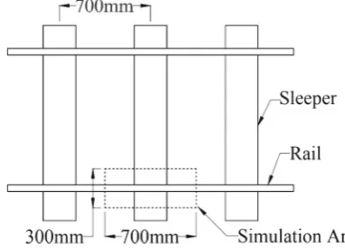
The box test which is used to model the ballast–sleeper inter-action that occurs under the rail seat of a track (Fig.2) has been used with success in previous studies [27,28]. It con-sists of loading cyclically a section of sleeper (0.3 m×0.25 m×0.15 m) embedded into ballast and confined in a 0.3 m x 0.7 m x 0.45 m box. The sleeper section is then loaded
Fig. 2 Simulated track area of box test
0 10 20 30 40
0 1 2 3 4 5 6 7
load (kN)
me (s)
Fig. 3 Loading path of the sleeper
Fig. 4 DEM sample of a box test
vertically with a 3 Hz cyclic load oscillating between 3 and 40 kN (Fig.3); 15 cycles are loaded for all the simulations in this study. It is not possible at this stage to carry out large numbers of cycles due to computational time; in addition the largest changes in measured quantities are always most perti-nent in the first few cycles. The stress level is achieved using a servo control mechanism.
The commercial DEM code PFC3D 5.0 [29] is used in this study. Figure4shows the DEM model of the box test. The sample is generated by the following procedure:
1. The ballast particles (modelled using ‘clumps’) are cre-ated in a taller box above the box test apparatus and are then allowed to settle under a normal gravity of−10 m/s2. 2. Change the gravity constant to−50 m/s2and then run the
sample until equilibrium state to compact the sample. 3. Switch the gravity constant to the normal value of
[image:2.595.53.287.52.214.2] [image:2.595.308.542.53.200.2] [image:2.595.310.541.232.413.2] [image:2.595.67.258.560.698.2]Fig. 5 Ballast particle shape
The sleeper is simply modelled as a group of elastic walls (Fig.4). The classic Hertz–Mindlin contact model [29] is used for the ballast particles and they are given a Poisson’s ratio,ν=0.25 and a shear modulus, G=28 GPa which are typical values for quartz. Lu and McDowell [13] have shown the importance of DEM modelling ballast particle shape in a box test, therefore the ballast particle in this study is modelled by an unbreakable clump [29] with realistic particle shape (Fig.5). PFC3D is able to create an irregular shaped clump quite simply by using the bubble pack algorithm of Taghavi [30]. The method generally fills a known 3D boundary using spheres of various sizes. It is governed by two parameters:
[image:3.595.208.543.58.204.2]c_disandc_ratio. Thec_discorresponds to an angular mea-sure of roughness in degrees ( 0<c_di s<180) as defined in Taghavi [30], thec_ratiodenotes the ratio of smallest to largest sphere forming the clump (0 < c_ratio < 1). The greaterc_disand the smallerc_ratio, the smoother the clump surface, they are chosen as 150◦and 0.4 in this study. The surface of the particle in this study (Fig.5a) is derived by scanning a real ballast particle using a 3D scanner, as detailed
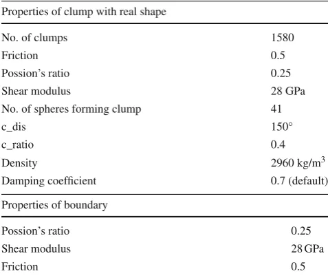
Table 1 Input parameters of clump particle and boundary Properties of clump with real shape
No. of clumps 1580 Friction 0.5 Possion’s ratio 0.25 Shear modulus 28 GPa No. of spheres forming clump 41 c_dis 150◦ c_ratio 0.4 Density 2960 kg/m3 Damping coefficient 0.7 (default) Properties of boundary
Possion’s ratio 0.25 Shear modulus 28 GPa Friction 0.5
in Li et al [31]. The nodes of the scanned surface are then input to PFC5.0 in the form of STL file. In terms of calculating the inertia tensor, the particle is assumed to have uniform density, the input surface (the actual particle shape in Fig.5a) is then divided into a set of tetrahedrons formed by the facet vertices and the centre of mass (the discretized boundary in Fig.5b), the covariance (second moment of mass) of each tetrahedron is then computed and added to an accumulator, at last the covariance matrix is converted to an inertia tensor. This is to say, the inertia tensor of the clump is calculated based on the mesh of input boundary although the forces acting on the clump are calculated based on the spheres forming the clump. In order to avoid non-physical oscillation within the assembly of objects, non-viscous (i.e. inertial) damping reduces their accelerations by 70 % (by default) to allow further dissipa-tion of energy in addidissipa-tion to fricdissipa-tional dissipadissipa-tion at contacts [29]. Table1lists all the input parameters of the particles.
3 Discrete element modelling of under
sleeper pad
[image:3.595.50.289.508.710.2]Fig. 6 aUSP used in DEM simulationbThe ball–ball contact model inside the USP
Table 2 The target engineering properties of USP and the characteristic parameters of contact models
Desired engineering properties of USP
Thickness 9mm Weight 5.6 kg/m2
Stiffness 0.079–0.105 N/mm3 Contact models: characteristic parameters
Linear contact model Normal stiffnessklcnand Shear stiffnessklcs
Contact bond model Normal stiffnesskcbnand Shear stiffnesskcbsNormal strengthσcbn
and shear strengthσcbs
Parallel bond model Normal stiffnesskpbnand Shear stiffnesskpbsNormal strength σpbnand shear strengthσpbsand bond radius multiplierα
Table2lists the physical parameters of the USP [8] mod-elled in this study and also the characteristic parameters for the three contact models The thickness is easily achieved by adjusting the radius of USP spheres and the weight simply depends on the density of mini-sphere. In terms of stiff-ness, the USP used in the experiment has a value range of 0.079−0.105 N/mm3, so the mean value 0.092 N/mm3 is chosen to be the target value in the simulation. As Fig.6b illustrates, the normal stiffness of the pad in compression
Kpad_ccan be derived by summing the stiffnesses of the
lin-ear contact model and parallel bond model (Eq.1), whereas the normal stiffness of the pad in tension Kpad_t can be derived by summing the stiffnesses of the contact bond model and parallel bond model (Eq.2). Considering the unit of tar-get stiffness is in N/mm3, theequations could be written as:
Kpad_c= F u∗Aball +
F u∗Aphb =
klcn Aball +
kpbn (1)
Kpad_t = F u∗Aball +
F u∗Aphb =
kcbn Aball +
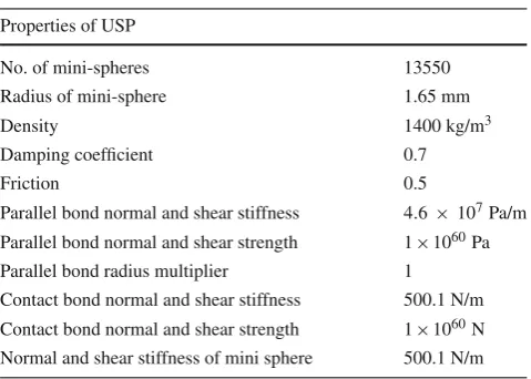
Table 3 Input parameters of USP Properties of USP
No. of mini-spheres 13550 Radius of mini-sphere 1.65 mm Density 1400 kg/m3
Damping coefficient 0.7 Friction 0.5
Parallel bond normal and shear stiffness 4.6×10⁷Pa/m
Parallel bond normal and shear strength 1×1060Pa
Parallel bond radius multiplier 1 Contact bond normal and shear stiffness 500.1 N/m Contact bond normal and shear strength 1×1060N Normal and shear stiffness of mini sphere 500.1 N/m
whereFstands for the compressive force acting on the ball,
uis the overlap caused by the compression force,Aball rep-resents the equivalent loading area of the ball andAphbis the area of parallel bond acting at the ball–ball contact. As the balls forming the pad are hexagonal closed packed, the equiv-alent areaAballis assumed to be the area of the square of the same side length as the diameter of sphere. The authors also assume the parallel bond and ball have the same strain under the same compressive force to model a homogenous mate-rial. Therefore, by equating the Eqs.1,2to 0.092 N/mm3, the normal stiffness of the parallel bond kpbn is set to be 4.6×10⁷Pa/m and the normal stiffnesses of the mini-sphere
klcn and the contact bond modelkcbn are calculated to be 500.1 N/m. The shear stiffness is assumed to be equal the nor-mal stiffness to simplify the calibration process in this study and various values will be investigated in a future study. The shear/normal bond strengths for both contact bond model and parallel bond model are given artificially large values to make the pad unbreakable. The parallel bond radius multiplierα [29], which is equal to the parallel bond radius divided by the radius of mini sphere, is assumed to be 1 to give the par-allel bond the same diameter with the mini sphere. The input parameters are listed in Table3.
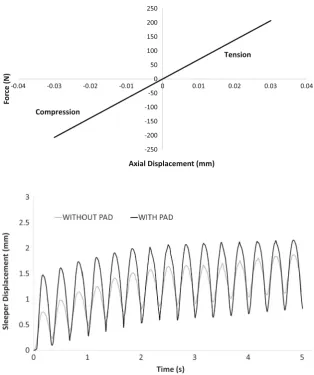
These values are then verified by 1D compression/tension test on the pad (Fig.7). The compression test is simply done by placing the pad between two parallel walls, and then mov-ing the upper wall downwards relative to the fixed bottom
wall. The displacement and the resulting force of the upper wall are recorded. For the tension test, a constant velocity was applied at both the upper and lower layers of particles. The axial strain and the total resulting forces at the upper and lower layers of particles are monitored during the test. Figure8shows the resulting force as a function of axial dis-placement in terms of both tension and compression. It shows the stiffness of the pad is exactly 0.092N/m3. So the USP exhibits linear-elastic behaviour.
4 Results and analysis
Baghsorki et al [8] observed experimentally that the USP reduced the permanent settlement of the sleeper and decre-ased the trackbed stiffness. The trackbed stiffness is calcu-lated according to Lim [32] as
K = Fmax −Fmi n
δmax −δmi n
(3)
whereKdenotes trackbed stiffness,Fmax−Fmi nrepresents the change in applied loading force on the sleeper andδmax− δmi nrepresents the resilient vertical displacement.
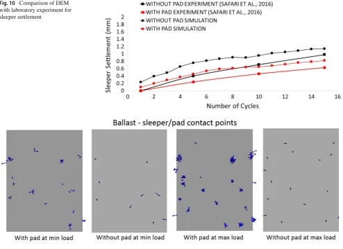
Due to the limitation of computation time, the simulations in this study were only repeated twice (i.e., two different ran-dom samples) and the average values are used to analysis here. Figure9shows the sleeper deflection as a function of time during the whole 15 simulation cycles for both cases with and without the USP. It shows that the pad clearly reduces the permanent settlement and the reduction by using a USP is enlarging with increasing loading time. It is also found that the USP increases the resilient vertical displace-ment of the sleeper during each cycle, which means a smaller trackbed stiffness corresponding to Eq.1. Figure10records the permanent settlement of each loading cycle (minimum points of each cycle in Fig.9) and then compares them with experimental results [8]. It can be seen that the permanent set-tlements predicted by the DEM simulations are only slightly higher than the experimental results. Moreover, the reduction in settlement by applying USP is also estimated. Figure11 compares the calculated trackbed stiffness of simulations to
Fig. 8 Verification of USP stiffness
-250 -200 -150 -100 -50 0 50 100 150 200 250
-0.04 -0.03 -0.02 -0.01 0 0.01 0.02 0.03 0.04
Fo
rc
e (
N
)
Axial Displacement (mm)
Tension
Compression
Fig. 9 Sleeper deflection versus time for simulations
with/without pad
experimental results. It can be seen that the DEM simulation slightly overestimates the trackbed stiffness for both cases.
It is easy to understand why the trackbed stiffness reduces, as the soft pad allows larger resilient settlement during each loading cycle. However it is still necessary to analyse the mechanism as to how the pad effects the permanent settle-ment. Figure12compares the contacts between particle and USP/sleeper at minimum and maximum load during the last loading cycle, which confirms that the USP allows more bal-last particles to support the load.
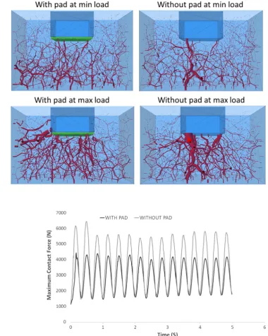
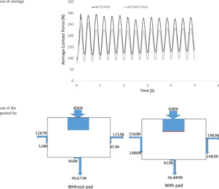
Figure13shows the contact force networks for both cases at minimum load and maximum load of the last loading cycle respectively. All lines of force are drawn to the same scale, where thicker lines represent larger forces. The comparisons indicate that the load distribution without a pad is mainly oriented vertically under the sleeper while the case with a pad seems to give greater diffusion of load laterally. Figures14 and15compare the maximum and average contact forces respectively throughout the simulations. It is clear that the USP results in a smaller maximum contact force but a larger
average contact force. This is to say, the application of the pad results in a more homogeneous load distribution and thus increases the number of ballast particles supporting the applied load.
[image:6.595.230.545.52.428.2]Fig. 10 Comparison of DEM with laboratory experiment for sleeper settlement
[image:7.595.55.545.438.609.2]Fig. 11 Comparison of DEM with laboratory experiment for trackbed stiffness
Fig. 12 The active contacts at particle–sleeper/pad interface
in terms of permanent settlement because there is more lateral diffusion of load.
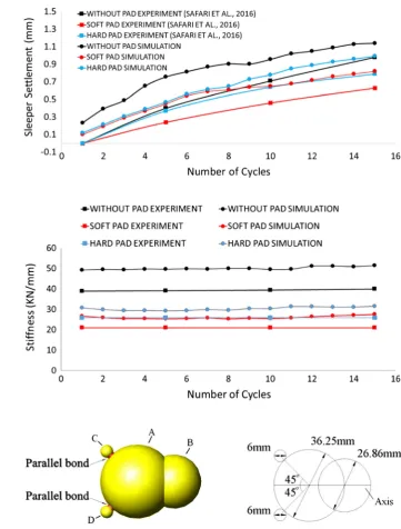
Baghsorki et al [8] also tested another harder USP with stiffness of 0.228–0.331 N/mm3 in their experiments. This pad was also modelled in this study; the parallel bond
and contact bond properties were calibrated using the same method explained in previous section and their values are listed in Table4.
Fig. 13 Contact force networks at 15th loading cycle
Fig. 14 Comparison of max contact force
stiffness respectively. Similar to the case using the soft pad, the DEM simulation gives a reasonable estimate for both settlement and stiffness. Moreover, the DEM simulation cor-rectly predicts the effect of changing the pad stiffness found in experiments: a softer pad results in less permanent settle-ment and smaller trackbed stiffness.
5 Particle abrasion
As particle breakage is one main causes of ballast degrada-tion, investigating the effect of USP on ballast breakage is also an aim of this study. In terms of DEM modelling ballast
crush-Fig. 15 Comparison of average contact force
[image:9.595.111.542.57.428.2]Fig. 16 Comparison of the contact forces supported by boundary
Table 4 The input bonds properties of hard pad
Parallel bond normal and shear stiffness 2.76×10⁸Pa/m
Parallel bond normal and shear strength 1 ×1060Pa
Parallel bond radius multiplier 1
Contact bond normal and shear stiffness 3 ×10³N/m Contact bond normal and shear strength 1 ×1060N Normal and shear stiffness of mini sphere 3 ×10³N/m
ing was found to initiate at the interface between the asphalt layer and the granular base and then continued to spread towards the bottom of the base layer. There are also a few studies where [36,37] particle shapes were modelled but par-ticle breakage was ignored. For limited studies considering both complex shape and breakage [31,38–41], agglomerates of bonded balls was used to represent ballast particles, which makes the computation time-consuming and releases internal voids on fracture, causing artificial settlement. Considering most ballast degradation is not attributable to particle
split-ting but instead primarily particle abrasion [42,43], Lu and McDowell [44] provided a breakable irregular shaped parti-cle: a simple two-ball clump with two additional breakable asperities bonded to the clump surface (Fig.19). Although this particle model cannot predict the track settlement quan-titively [45], it successfully modelled the effect of ballast abrasion on permanent track settlement [37] and provided relatively fast computational speed. Considering the main aim of this section is to investigate the effect of using USP on particle abrasion, this particle model (Fig.19) is used in this group of simulations. The particle and parallel bonds used in the simulation are those used by Lu and McDow-ell [44], and the parameters are listed in Table5. The USP used in this simulation is the soft pad used in the previous section.
[image:9.595.51.290.479.563.2]Fig. 17 Comparison of sleeper settlement for various pads
Fig. 18 Comparison of trackbed stiffness for various pads
Fig. 19 Breakable particle model
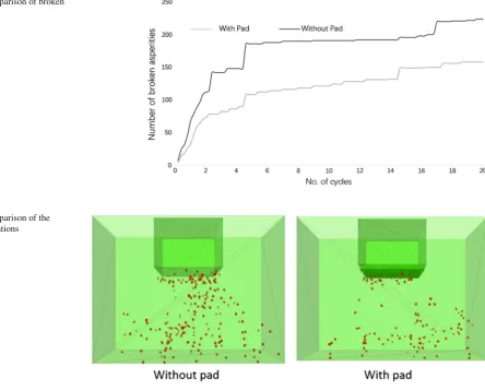
[image:10.595.307.545.558.700.2]13which show the corresponding contact force networks, it is observed the breakages mainly occur at the sleeper/USP– particle interface and along the main contact force chains under the sleeper. It is clear that the number of breakages reduces for both of these zones of breakage when using an USP. For the particles in contact with the USP, the larger contact area reduces the contact pressure and therefore there are fewer particle abrasions. Regarding to the inter-particle breakage, Fig. 14 shows the maximum contact forces are generally smaller for the case with a USP, which explains why there are fewer inter-particle breakages.
Table 5 Input parameters of clump with breakable asperities Input parameters of two-ball clump
No. of clumps 1632 Density 2960 kg/m3 Damping coefficient 0.7 (default) Friction 0.5 Poisson’s ratio 0.25 Shear modulus 28 GPa
Fig. 20 Comparison of broken asperities
Fig. 21 Comparison of the breakage locations
6 Conclusions
DEM of a box test on ballast has been used to give micro mechanical insight into how Under Sleeper Pads improve the performance of ballasted railway track. This was modelled by representing the USP using three layers of small bonded spheres, and using a realistically shaped clump to represent the ballast particle. This DEM model cannot only qualita-tively predict the improvement of applying a USP but also quantitively match the experimental results. The pads with different stiffnesses can also be simply modelled by chang-ing the stiffness of bonds and spheres formchang-ing the pad. The micro-level analysis of DEM models indicates that by using a USP, more particles are effectively allowed to contact with the sleeper/pad composite system. It is also found that the contact force chains are concentrated underneath the sleeper for the case without USP whereas the USP provides a more homogeneous load distribution. Thus the USP transmits a smaller force vertically to the base, which is believed to be the reason why USP helps to reduce the track settlement. Par-ticle abrasion was also considered by using a simple two ball clump with two breakable asperities, and it was found that breakage occurs mainly at the particle–sleeper interface and
along the main contact force chains beneath the sleeper. Par-ticle abrasion in both zones is reduced by the use of an under sleeper pad in the simulations. This work therefore lends credibility to the use of USPs in practice to reduce track set-tlement, and in the reduction of ballast abrasion caused by trafficking which ultimately causes a deterioration in track performance.
Acknowledgements This work was supported by the Engineering and Physical Sciences Research Council [grant number EP/M025276/1], the authors would like to thank the EPSRC project for funding this work.
Compliance with ethical standards
Conflict of interest The authors also declare that they have no financial and personal relationships with other people or organizations that can inappropriately influence their work.
References
1. Johansson, A., Nielsen, J.C.O., Bolmsvik, R., Karlström, A., Lundén, R.: Under sleeper pads-influence on dynamic train–track interaction. Wear265, 1479–1487 (2008)
2. Bolmsvik, R.: Influence of USP on the track response—a literature survey. Abetong Teknik AB, Heidelberg (2005)
3. Witt, S.: The influence of under sleeper pads on railway track dynamics, report LIU-IEI-A–08/00442- SE. Linkoping University, Linkoping, Sweden (2008)
4. Schneider, P., Bolmsvik, R., Nielsen, J.C.O.: In situ performance of a ballasted railway track with under sleeper pad. Proc. Inst. Mech. Eng. Part F J. Rail Rapid Transit225, 299–309 (2011)
5. Riessberger, K.: Ballast tracks for high speeds. In: Proceedings of Tracks for High-Speed Railways, pp. 23–44 (2006)
6. Abadi, T., Pen, L.Le, Zervos, A., Powrie, W.: Measuring the area and number of ballast particle contacts at sleeper/ballast and bal-last/subgrade interfaces. Int. J. Railw. Technol.4, 45–72 (2015) 7. Lakuši´c, S., Ahac, M., Haladin, I.: Experimental investigation of
railway track with under sleeper pad. In: 10th Slovenian Road and Transportation Congress, 20–22 October (2010)
8. Baghsorkhi, M.S., Laryea, S., Mcdowell, G., Thom, N.: An inves-tigation of railway sleeper sections and under sleeper pads using a box test apparatus. Proc. Inst. Mech. Eng. Part F J. Rail Rapid Transit230, 1722–1734 (2016)
9. Loy, H.: Under sleeper pads in turnouts. RTR. Eur. Rail Technol. Rev.2, 2–5 (2009)
10. Cundall, P.A., Strack, O.D.: A discrete numerical model for gran-ular assimblies. Geotechnique29, 47–65 (1979)
11. Lobo-guerrero, S., Vallejo, L.E.: Discrete element method eval-uation of granular crushing under direct shear test conditions. J. Geotech. Geoenviron. Eng.131, 1295–1300 (2005)
12. Lobo-Guerrero, S., Vallejo, L.E.: Discrete element method analy-sis of railtrack ballast degradation during cyclic loading. Granul. Matter8, 195–204 (2006)
13. Lu, M., McDowell, G.R.: The importance of modelling ballast par-ticle shape in the discrete element method. Granul. Matter9, 69–80 (2006)
14. Price, M., Murariu, V., Morrison, G.: Sphere clump generation and trajectory comparison for real particles. In: Proceedings of Discrete Element Modelling (2007)
15. Wang, L., Park, J., Fu, Y.: Representation of real particles for DEM simulation using X-ray tomography. Constr. Build. Mater.21, 338– 346 (2007)
16. Ferellec, J.-F., McDowell, G.R.: A simple method to create com-plex particle shapes for DEM. Geomech. Geoengin.3, 211–216 (2008)
17. Ferellec, J., McDowell, G.R.: A method to model realistic particle shape and inertia in DEM. Granul. Matter12, 459–467 (2010) 18. Lu, M., McDowell, G.R.: Discrete element modelling of railway
ballast under triaxial conditions. Geomech. Geoengin.3, 257–270 (2008)
19. Lu, M., McDowell, G.R.: Discrete element modelling of railway ballast under monotonic and cyclic triaxial loading. Géotechnique
60, 459–467 (2010)
20. Mcdowell, G.R., Li, H.: Discrete element modelling of scaled rail-way ballast under triaxial conditions. Granul. Matter 18, 1–10 (2016)
21. Harkness, J., Zervos, A., Powrie, W., Le Pen, L.: Discrete element simulation of railway ballast: modelling cell pressure effects in triaxial tests. Granul. Matter18, 65 (2016)
22. Indraratna, B., Hussaini, S.K.K., Vinod, J.S.: The lateral displace-ment response of geogrid-reinforced ballast under cyclic loading. Geotext. Geomembr.39, 20–29 (2013)
23. Qian, Y., Mishra, D., Tutumluer, E., Kazmee, H.A.: Characteri-zation of geogrid reinforced ballast behavior at different levels of degradation through triaxial shear strength test and discrete element modeling. Geotext. Geomembr.43, 393–402 (2015)
24. Ngo, N.T., Indraratna, B., Rujikiatkamjorn, C.: Computers and geotechnics DEM simulation of the behaviour of geogrid stabilised ballast fouled with coal. Comput. Geotech.55, 224–231 (2014) 25. Tutumluer, E., Ph, D., Asce, M., Huang, H., Ph, D., Bian, X., Ph,
D.: Geogrid-aggregate interlock mechanism investigated through aggregate imaging-based discrete element modeling approach. Int. J. Geomech.3, 391–398 (2012)
26. Mcdowell, G.R., Lim, W.L., Collop, A.C., Thom, N.H., Armitage, R.: Laboratory simulation of train loading and tamping on ballast. Proc. Inst. Civ. Eng.158, 89–95 (2005)
27. Lim, W.L., McDowell, G.R.: Discrete element modelling of railway ballast. Granul. Matter7, 19–29 (2005)
28. Mcdowell, G., Stickley, P.: Performance of geogrid-reinforced bal-last. Ground Eng.39, 26–30 (2006)
29. Itasca: PFC3D v5.0-user manual. Itasca Consulting Group, Min-neapolis (2015)
30. Taghavi, R.: Automatic clump generation based on mid-surface. In: Proceedings, 2nd International FLAC/DEM Symposium, Mel-bourne, pp. 791–797 (2011)
31. Li, H., McDowell, G., Lowndes, I.: Discrete element modelling of a rock cone crusher. Powder Technol.263, 151–158 (2014) 32. Lim, W.L.: Mechanics of railway ballast behaviour. Ph.D. thesis,
University of Nottingham (2010)
33. Lobo-Guerrero, S., Vallejo, L.E.: Influence of pile shape and pile interaction on the crushable behavior of granular materials around driven piles: DEM analyses. Granul. Matter9, 241–250 (2007) 34. Lobo-Guerrero, S., Vallejo, L.E.: DEM analysis of crushing around
driven piles in granular materials. Geotechnique 55, 617–623 (2005)
35. Lobo-Guerrero, S., Vallejo, L.E.: Degradation of a granular base under a flexible pavement: DEM simulation. Int. J. Geomech.6, 435–439 (2006)
36. Tutumler, E., Huang, H., Hashash, Y., Ghaboussi, J.: Discrete ele-ment modeling of railroad ballast settleele-ment. In: AREMA Annual Conference (2007)
37. Huang, H., Tutumluer, E.: Discrete element modeling for fouled railroad ballast. Constr. Build. Mater.25, 3306–3312 (2011) 38. Cleary, P.W., Sinnott, M.D.: Simulation of particle flows and
break-age in crushers using DEM: Part 1—compression crushers. Miner. Eng.74, 178–197 (2015)
39. Zhang, X., Zhao, C., Zhai, W.: DEM analysis of ballast breakage under train loads and its effect on mechanical behaviour of rail-way track. In: Proceedings of the 7th International Conference on Discrete Element Methods (2017)
40. Delaney, G.W., Morrison, R.D., Sinnott, M.D., Cummins, S., Cleary, P.W.: DEM modelling of non-spherical particle breakage and flow in an industrial scale cone crusher. Miner. Eng.74, 112– 122 (2015)
41. Fu, R., Hu, X., Zhou, B.: Discrete element modeling of crushable sands considering realistic particle shape effect. Comput. Geotech.
91, 179–191 (2017)
42. Indraratna, B., Christie, D.: Effect of confining pressure on the degradation of ballast under cyclic loading. Geotechnique55, 325– 328 (2005)
43. Aursudkij, B.: A laboratory study of railway ballast behaviour under traffic loading and tamping maintenance. Ph.D. thesis, Uni-versity of Nottingham (2007)