Janneke Veerbeek
Chemical Engineering
Graduation committee
Prof. dr. ir. J. Huskens
S.O. Krabbenborg, M.Sc.
C. Nicosia, M.Sc.
Prof. dr. S.G. Lemay
Molecular NanoFabrication
Faculty of Science and Technology
MESA+ Institute for Nanotechnology
Enschede, July 10
th2012
3
Abstract
Directed motion of molecules is necessary for the controlled buildup of molecular architectures, local reactions at the nanoscale, and for fundamental understanding of processes at the molecular scale. While the synthesis of gradients has been studied extensively, almost no research has been performed on the directed motion of molecules by chemical gradients. The few studies available did not include any tunable and dynamic gradients.
Therefore, the research performed in this project aimed for the directed motion of molecules by using electrochemically controlled gradients. Supramolecular chemistry and electrochemistry were combined because of their reversibility and tunability/downscaling characteristics, respectively. Multivalent interactions were used to ensure tunability by competition or electrochemistry instead of spontaneous desorption.
At first, a covalent host surface gradient on glass was fabricated at the μm scale. Click chemistry was used to synthesize a surface gradient of coumarin units. CD molecules were reacted on top, thus forming a host surface gradient which could be visualized by fluorescence spectroscopy. Incubation with guest molecules led to a gradient in the wrong direction, which has to be further investigated.
Secondly, a non-covalent surface gradient of guest molecules was created for the first time, to our knowledge. A solution gradient of FcMeOH was produced electrochemically, that acted as a competitor for Ad2-rhodamine on the CD printboard and resulted in a surface gradient of guest
molecules at the μm scale. The direction of the gradient could be reversed by adding CD in solution. Further research is necessary to optimize the gradients, e.g. in steepness.
Thirdly, directed motion was intended to occur via a surface gradient of host molecules, or a solution gradient of a host or competitor. Motion on the synthesized host and guest gradients was not tried yet. Directed motion was tested by unequal spreading of microcontact printed lines with a host solution gradient on top. This resulted in a higher spreading rate, but no directed spreading was observed.
5
Table of contents
1 Introduction ... 6
2 Theoretical background ... 8
2.1 Directional motion ... 8
2.2 Surface gradients ... 9
2.3 Inducing directed motion by using surface gradients ... 11
2.4 Molecular printboard of CD with ferrocene as redox active guest molecule ... 13
2.5 Research strategy ... 15
3 Experimental details ... 16
3.1 Synthesis of Fc4-rhodamine ... 16
3.2 Gradient formation and motion ... 18
4 Covalent host gradient formation ... 26
4.1 Host gradient on glass ... 26
4.2 Host gradient on gold ... 29
4.3 Summary... 31
5 Non-covalent guest gradient formation ... 32
5.1 Ferrocene-functionalized guest molecules ... 32
5.2 Characterization of CD molecular printboard on glass ... 35
5.3 Guest gradient on glass by a sink of divalent guest molecules ... 36
5.4 Guest gradient on glass with K3IrCl6 as mediator ... 37
5.5 Guest gradient on glass with FcMeOH as competitor ... 42
5.6 Guest gradient on gold ... 45
5.7 Summary... 47
6 Steering molecular motion by surface gradients ... 48
6.1 Symmetric spreading of microcontact printed lines ... 48
6.2 Directed spreading of microcontact printed lines... 50
6.3 Summary... 52
7 Conclusions ... 53
8 Recommendations ... 54
8.1 Avoid the divalent and tetravalent ferrocene guests ... 54
8.2 Problems with increasing background ... 54
8.3 Visualization method on gold ... 55
8.4 Host gradient on glass ... 55
8.5 Guest gradient on glass with FcMeOH as competitor ... 55
8.6 Motion ... 56
Acknowledgements ... 57
References ... 58
Appendix A. Characterization of Fc4-rhodamine ... 61
A.1 NMR spectroscopy ... 61
A.2 Mass spectrometry ... 62
6
1
Introduction
The control of motion at the molecular scale is necessary for the controlled buildup of molecular architectures, local reactions between nanoobjects in a controlled way, and for fundamental understanding of processes at the molecular scale. Since nature offers a lot of examples of directed motion, it is useful to 1) implement biological molecular motors in artificial systems, such as systems based on kinesin [1], or 2) mimic these processes to produce fully synthetic systems, such as a molecular walker [2, 3] or molecular machines [4]. In this way, biological (active) motion is translated to molecular (passive) motion. Different methods have been used to obtain directional passive motion of nanoobjects, i.e. by electrical fields [5, 6], magnetic fields [7], optical traps [8], and chemical gradients [9, 10].
Another well-studied subject in nature is the haptotaxis of cells, where cells move in the direction of higher nutrient concentration by a gradient in cellular adhesion receptors [11]. This can be translated to the use of synthetic surface gradients to direct the motion of molecules, where a gradient may be defined as a gradual change of a property [12]. Whereas haptotaxis is a well-studied subject, the research within the synthetic field is still in its infancy.
Although the synthesis of gradients has been extensively studied in recent years [12, 13], only a few studies have investigated the control of molecular motion by gradients. The directed motion by chemical gradients is even scarcer, while chemical gradients have many advantages over physical techniques. These advantages include chemical specificity, the possibility to control the duration and the speed of the movement, and the extension to 2D control by two orthogonal gradients. Examples of directed motion by chemical gradients include the directed motion of dendrimers via an aldehyde gradient [14], the directed diffusion of single molecules induced by a hydrophobicity gradient [10, 15], and the direction motion of guest molecules on an evolving gradient of uncomplexed host molecules [16]. However, none of them included a tunable gradient or a dynamic change of properties over time.
So, while the control of motion is an interesting and promising area, motion induced by chemical gradients is hardly investigated. Most chemical gradients are made at the millimeter (mm) scale or even larger. However, to control the motion of molecules, smaller gradients are necessary. Therefore, electrochemistry was used in this report to induce gradient formation, so a smaller scale could be easily achieved by downscaling the size of the electrodes and of the gaps between them. Because of the use of electrochemistry, gradient formation becomes tunable by switching on/off or changing the potential. In contrast, conventional solution gradients only stop when the solution is removed. Within the Molecular NanoFabrication (MnF) group at the University of Twente, micrometer (µm) solution gradients are being fabricated by electrochemistry and transferred to surface gradients.
7
8
2
Theoretical background
This chapter gives an overview of the literature on the synthesis of gradients and the directed motion of nanoobjects. At first, two famous examples of directional motion based on natural systems are described. The synthesis of surface gradients is reviewed briefly, most of them on the mm scale or even larger. Subsequently, the directed motion by surface gradients is reviewed. Finally, the properties of CD printboards and in specific the interactions between CD and ferrocene-functionalized redox active guest molecules are described.
2.1
Directional motion
Many synthetic systems for directional motion are based on natural systems. Two famous examples are described below, including one natural system and one fully synthetic system.
Vogel et al. [1] have used kinesin tracks to direct the motion of microtubules powered by adenosine triphosphate (ATP). The microtubules were guided by patterning a kinesin-coated polyurethane surface with 2 μm wide and 1 μm deep channels (Figure 2.1), but climbing against a wall was also observed. The microtubules could be loaded with cargo and transport these beads across the surface. The velocity of the microtubules could be rapidly increased by exposure to UV light, since that released caged ATP. Although directional motion could be obtained by the surface topography, the initial direction of movement is still random. Asymmetric channel features could be used to limit the bidirectional motion to unidirectional motion [21], but then the direction cannot be turned around.
Figure 2.1. a) Schematic representation of the system to direct the motion of microtubules by a patterned surface of kinesin, and b) movement of microtubules on a kinesin-coated polyurethane surface patterned with 2 μm wide and 1 μm deep channels [1]
In order to mimic biological motor proteins, Leigh et al. [2] have produced a molecular walker. They synthesized a molecule, consisting of two legs and 21 atoms, that could walk up and down a so-called four-foothold molecular track (Figure 2.2). The interactions between the walking molecule and the different feet are labile under other conditions (acidic (condition I) or basic (condition II)), so that one end of the molecule can be temporarily fixed to one foot. This resulted in a random walking process, since the probability to move backwards or forwards is equal in every step. When one of the reactions was replaced by a kinetically controlled redox reaction, the directed motion was increased for one step (condition III). The use of covalent bonds is advantageous because their bond strength prevents complete detaching, but it is disadvantageous that the experimental conditions have to be switched for every step.
9
Figure 2.2. Four-foothold molecular track upon which a two-legged molecule walks up and down [2]
2.2
Surface gradients
The synthesis of patterns by using lithography techniques, for example soft lithography [22], has attracted considerable attention during the past few years. These techniques are very useful for creating surface patterns, even down to the nanoscale. However, by using these techniques, a sharp border is established between the patterned and the unpatterned areas. Many recent studies have therefore focused on the synthesis of surface gradients instead of sharp borders, where a gradient can be defined as a gradual change of a property [12]. Applications of these surface gradients include the fast screening of physicochemical phenomena, the fabrication of material structures that are normally difficult to produce, recording method for monitoring a process, or the use to drive [9] and/or direct a transport phenomenon [13].
The synthesis of surface gradients can be subdivided into bottom-up and top-down methods [13] (Figure 2.3). Bottom-up techniques include the buildup of gradients by gradually depositing different building blocks. This can be achieved by 1) spontaneous deposition methods, i.e. via diffusion or a propagating front, or 2) controlled processes, i.e. sample dipping into a solution, deposition-dependent methods or external field-assisted methods. On the other hand, top-down methods include a starting material that is modified chemically or physically, e.g. the reductive desorption of thiols by an in-plane gradient on gold. Within this process, different techniques can be combined to make a gradient geometry. Furthermore, it is also possible to create a substrate-free gradient that is subsequently transferred onto a support, for example the formation of a chemical gradient inside a microfluidic chip.
Figure 2.3. Examples of methods to create surface gradients via bottom-up techniques: a) liquid diffusion of organosilanes, and b) forming a molecular gradient of an initiator on a substrate followed by grafting-from polymerization; or via top-down methods: c) hydrolysis of poly(vinylene carbonate), and d) replacement lithography of alkanethiols [13]
The properties of surface gradients can be subdivided into different categories [13] (Figure 2.4): directionality (orthogonal, radial or directional), time dependency (static or dynamic), dimensionality (1D, 2D or 3D), functionality, type of interactions (chemical or physical) and length scale (discrete or continuous).
d c
10
Figure 2.4. Overview of different properties surface gradients [13]
Concerning time dependency, almost all studied gradients are static, meaning that the gradient is fixed after production [13]. This can be applied to the screening of material properties, or a dynamical process such as the movement of liquids along surfaces. However, it is also possible to fabricate surface gradients whose properties change in time when varying an external stimulus (temperature, pH, external electrical field, ion concentration, etc.). These dynamic gradients can be used to drive a certain phenomenon, i.e. motion of liquids, particles, living cells or mixing liquids.
With respect to the length scale, almost all studied gradients are on the mm scale or even larger. Only a few studies have investigated the production of (sub)µm gradient patterns, which is desired to control the motion of nanoobjects. However, no literature was found about (sub)µm gradients with a dynamic change of properties in time.
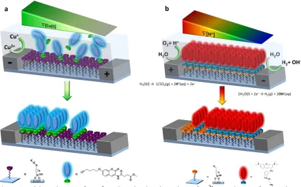
[image:10.595.69.448.82.378.2]11
Figure 2.5. (a) Production of a Cu+ gradient by the electrolysis of Cu2+ to make a surface gradient of an alkyne dye and (b) production of a pH gradient by the electrolysis of water to make a surface gradient of an amine dye by pH-dependent imine-bond hydrolysis.
2.3
Inducing directed motion by using surface gradients
In biology, haptotaxis [15] means that cells are moving on a surface directed by an external chemical gradient, which is a well-studied area. Synthetic surface gradients have been studied extensively already [12, 13], but only a few studies have already investigated the directed motion of (nano)objects or molecules by using surface gradients. These few studies are described in this section.
At first, Chang et al. [14] reported the directed motion of dendritic macromolecules, which are labeled with a dye. They attached poly(propyleneimine) dendrimers to glass substrates by using multiple imine bonds. The movement of these dendrimers is based on the hydrolysis and reformation of the imine bonds. This movement is random without an external stimulus, but can be directed by applying an aldehyde gradient on the glass substrate instead of a homogeneous coverage with aldehyde groups. In this way, it is more likely that the dendrimer moves in one direction, since the change is higher to form imine bonds at a place where more aldehyde groups are present. The aldehyde gradient was generated by using dip coating and afterwards the dendrimers were printed onto the substrate (Figure 2.6).
12
Figure 2.6. Substrate preparation by modified dip coating and printing [14]
Furthermore, Burgos et al. [15] investigated the directed diffusion of single molecules induced by surface energy gradients. They produced a surface gradient by using selective photo-oxidation, so that the surface changes from hydrophilic to hydrophobic over a few micrometers. Single poly(ethylene glycol) chains were driven towards the hydrophilic side of the surface by diffusion. The diffusion coefficient on these surfaces was more than an order of magnitude higher than on surfaces without a surface energy gradient.
Walder et al. [10] also studied directed motion by using a gradient of hydrophobicity, made by using selective photodegradation (Figure 2.7). They used 20 nm particles instead of polymer chains and only a small fraction of the surface consisted of the gradient region.
Figure 2.7. Total internal reflection fluorescence (TIRF) microscope images showing a) three adsorbed nanobeads, b) the adsorption of a new nanobead, and c) movement of the new bead towards the region with higher hydrophobicity after 8 s [10]
13
Figure 2.8. Mechanisms involved in gradient-driven motion [16]
All systems are on the µm scale, except for the research of Chang et al. [14] that acts on the mm scale. However, the gradient formation of all these systems is not tunable and included a static instead of a dynamic gradient. Only the research of Perl et al. [16] included a dynamic gradient, since the amount of vacant host molecules changed in time. Nevertheless, this system was not tunable by an external stimulus to switch the gradient and the direction of the motion, as was desired in the research of this report.
2.4
Molecular printboard of CD with ferrocene as redox active guest molecule
Supramolecular chemistry includes non-covalent binding or complexation [23], where a molecule (a ‘host’) binds another molecule (a ‘guest’) to form a ‘host-guest’ complex. Mostly the host is a large molecule with a central hole or cavity, while the guest can be a monatomic cation, simple inorganic anion, an ion pair or a more sophisticated neutral or charged molecule (hormone, neurotransmitter, etc.). Supramolecular interactions are often established by hydrogen bonding, ionic bonds, hydrophobic forces and van der Waals forces.
In this report, supramolecular chemistry is used because of its reversibility and precise control over binding kinetics and thermodynamics [17]. The MnF group has already studied supramolecular chemistry extensively, in particular focused on β-cyclodextrin (CD) as the host molecule. Figure 2.9 shows the structure of β-cyclodextrin, a cyclic oligosaccharide that consists of seven glucopyranoside groups [23]. The cavity inside the molecules is hydrophobic due to the hydroxyl groups, which enables the complexation of organic guests in an aqueous solution, while the outer face is hydrophilic. Water molecules inside the cavity have a relatively high energy due to their limited interactions with the hydrophobic wall. Therefore, guest complexation is promoted by expulsion of these high-energy water molecules from the cavity.
14
The CD host molecules have been applied to the synthesis of molecular printboards [17, 20], which consist of self-assembled monolayers (SAMs) of CD on glass or gold. These printboards can bind guest molecules reversibly by hydrophobic interactions, for example guests with adamantyl groups. The systems based on divalent and trivalent guests are kinetically stable when only water is present. When free CD molecules are added to the solution, a part of the guest molecules desorbs due to competition, as shown in Figure 2.10. When a guest with multivalent interactions is used, i.e. two or more groups bind to the host surface, the supramolecular interactions are stronger and less competition with CD in solution occurs [16].
Figure 2.10. Schematic representation of the adsorption of guest molecules and their desorption by competition with CD in solution [20]
In this report, electrochemically controlled gradients were produced to obtain directed motion of molecules. Due to the use of reversible supramolecular interactions, a gradient could be produced by desorbing the guest molecule on a part of the surface only, for example. Consequently, a redox active guest was needed in most designed systems. Ferrocene-functionalized guest molecules were chosen, since ferrocene forms stable 1:1 complexes with CD, while the oxidized form, the ferrocenium ion Fc+, forms only very weak inclusion complexes with CD and thus desorbs from the surface. Different examples of Fc-CD systems were found in literature, as described below.
15
Figure 2.11. A monolayer of G3-PPI-(Fc)16 at the CD SAM on gold efficiently blocked the binding of
guest molecules from solution, e.g. G2-PPI-(Ad)8. Only electrochemically induced desorption of
G3-PPI-(Fc)16 exposed the free binding sites and G2-PPI-(Ad)8 can bind to the host surface [25].
Dubacheva et al. [26] also studied the adsorption/desorption behavior of ferrocene groups on a gold surface with CD SAMs, but they used ferrocene-functionalized polymers instead of dendrimers. All specifically attached polymer chains could be desorbed from the CD monolayer by applying a potential. Furthermore, Chen et al. [27] found that Fc-functionalized nanotubes formed host-guest complexes with CD SAMs, which were also tunable by electrochemistry. Ling et al. [28] used the Fc dendrimers employed by Nijhuis as a supramolecular glue to reversibly bind and unbind CD-functionalized nanoparticles.
2.5
Research strategy
In connection with the theoretical background described, a strategy was thought up for the research of this report. The designed systems were based on host-guest chemistry because of its reversibility and precise control over binding kinetics and thermodynamics [17]. Furthermore, supramolecular chemistry was chosen because the MnF group has studied this area extensively and has described an example of motion on supramolecular printboards already [16].
In order to obtain directed motion of molecules, the molecules had to ‘sense’ the gradient on the molecular scale. Therefore, gradients were produced on the μm scale and the density differences on the surface had to be as high as possible.
16
3
Experimental details
3.1
Synthesis of Fc
4-rhodamine
3.1.1
Materials
The following chemicals were used as received without further purification: dichloromethane (CH2Cl2,
Sigma-Aldrich, p.a.), N,N-diisopropylethylamine (DIPEA, Biosolve), ferrocenecarboxylic acid (FcCOOH, Acros, 97%), lissamine rhodamine B sulfonylchloride (mixture of isomers, sulforhodamine B acid chloride, Sigma), methanol (MeOH, Sigma-Aldrich, p.a.), oxalyl chloride (Acros, 98%), potassium carbonate (K2CO3, Acros, anhydrous), sodium bicarbonate (NaHCO3, Sigma-Aldrich), sodium sulfate
(Na2SO4, Sigma-Aldrich, anhydrous), tetrakis(acetonitrile)copper(I) hexafluorophosphate
([Cu(CH3CN)4]PF6, Aldrich), thiophosgene (CSCl2, Acros, 97%) and trifluoroacetic acid (TFA, Acros, 99%
extra pure). MilliQ water was used in all experiments.
Furthermore, 11-azido-3,6,9-trioxaundecan-1-amine [29], 3,5-diethynylaniline [30, 31], tert-butyl (6-(bis(3-aminopropyl)amino)hexyl)carbamate [24] and tris[(1-benzyl-1H-1,2,3-triazol-4-yl)methyl]amine (TBTA) [32] were synthesized by others according to literature procedures.
3.1.2
Synthetic procedures
Scheme 3.1. Synthesis route towards the fluorescent ferrocene-functionalized guest molecule 6: i. 3,5-diethynylaniline, Cu(CH3CN)4PF6, TBTA, CH2Cl2/MeOH, r.t., 24 h; ii. a. saturated NaHCO3, CH2Cl2,
0 °C, 5 min, b. CSCl2, r.t., 45 min; iii. tert-butyl (6-(bis(3-aminopropyl)amino)hexyl)carbamate, CH2Cl2,
r.t., o.n.; iv. TFA, CH2Cl2, 0 °C, 1 h; v. lissamine rhodamine B sulfonylchloride (mixture of isomers),
DIPEA, CH2Cl2, r.t., o.n.
Synthesis of 1. The synthesis of 1 ([[[2-[2-(2-azidoethoxy)ethoxy]ethyl]amino]carbonyl]-ferrocene) was adapted from the method described by Perl [33]. At first, ferrocenylcarbonyl chloride was synthesized [34] by adding oxalyl chloride (0.42 mL, 5.0 mmol) dropwise to a stirred solution of ferrocenecarboxylic acid (0.46 g, 2.0 mmol) in dichloromethane (30 mL). The solution was stirred at room temperature for 2 h under argon. Removing the solvent in vacuo resulted in ferrocenylcarbonyl chloride as red crystals, which were used subsequently without further purification. Thereafter, a suspension of 11-azido-3,6,9-trioxaundecan-1-amine (0.44 g, 2.0 mmol), ferrocenylcarbonyl chloride (0.50 g, 2.0 mmol) and K2CO3 (1.4 g, 5.0 mmol) was stirred at room temperature in 30 mL CH2Cl2 for
17
reduced pressure, the resulting red brown oil was subjected to column chromatography (SiO2,
CH2Cl2/MeOH = 98/2). This yielded product 1 in 72% yield (620 mg) as a dark red oil.
Synthesis of 2. A solution of 3,5-diethynylaniline (92.5 mg, 0.65 mmol) in 10 mL CH2Cl2 was added to
1 (620 mg, 1.4 mmol) dissolved in another 10 mL CH2Cl2 (ratio 1 : 2.2). Subsequently, under nitrogen
a solution of [Cu(CH3CN)4]PF6 (36.6 mg, 0.10 mmol) and TBTA (52.1 mg, 0.10 mmol) in methanol (5
mL) was added to the reaction mixture, since Cu+ ions are necessary for the click chemistry reaction (copper-catalyzed azide-alkyne cycloaddition). The mixture was stirred at room temperature for 24 h under argon. After evaporation of the volatiles under reduced pressure, the product was purified by column chromatography (SiO2, CH2Cl2/MeOH = 94/6), giving product 2 as yellow crystals (304 mg,
46%).
Synthesis of 3. To a cooled mixture (0 °C) of 2 (200 mg, 0.20 mmol) in 10 mL CH2Cl2 was added
saturated NaHCO3 (10 mL) and the biphasic mixture was stirred rigorously for 5 min. The stirring was
stopped and 1.1 equivalent of thiophosgene (16.8 µL, 0.22 mmol) was added via a pipet to the organic layer. The reaction mixture was removed from the ice bath and stirring was continued for 45 min. The layers were separated and the aqueous layer was extracted with CH2Cl2 (2 x 10 mL), dried
over Na2SO4 to remove water traces and filtered. The volatiles were evaporated under reduced
pressure and the product was used subsequently without further purification. The yield of this product is unknown.
Synthesis of 4. Under nitrogen, tert-butyl (6-(bis(3-aminopropyl)amino)hexyl)carbamate (27.5 mg, 0.083 mmol) was added to a solution of 3 (208 mg, 0.083 mmol) in CH2Cl2 (10 mL). The solution was
stirred overnight at room temperature under argon. The solvent was removed by evaporation under reduced pressure and the product was purified by preparative thin layer chromatography (Al2O3,
CH2Cl2/MeOH = 97/3). This resulted in the product in 50% yield (101 mg, 0.042 mmol). The low yield
is probably due to test experiments with column chromatography that did not work.
Synthesis of 5. The synthesis of 5 was adapted from the method described by A. Mulder [24]. To remove the protective t-Boc (tert-butyloxycarbonyl) group from 4, TFA (1 mL, 13.5 mmol, large excess) was added to a cooled solution of 4 (101 mg, 0.042 mmol) in CH2Cl2 (4 mL). This solution was
stirred for 1 h, after which the solvent was evaporated. Thereafter, the solution was diluted with 20 mL CH2Cl2. The residue was extracted with a saturated NaHCO3 solution (2 x 20 mL), dried over
Na2SO4 to remove water traces and filtered. Evaporating the solvent under reduced pressure resulted
in the free amine 5 (80 mg, 0.035 mmol, 83%) which was used subsequently without further purification.
MS (MALDI-TOF): m/z = 2320 [M+H]+(calcd. 2319)
Synthesis of 6. The synthesis of 6 was adapted from the method described by A. Mulder [24]. The fluorescent dye lissamine rhodamine B sulfonylchloride (mixed isomers, 29.9 mg, 0.052 mmol) was added to a solution of 5 (80 mg, 0.035 mmol) and DIPEA (17.6 µL, 0.10 mmol) in CH2Cl2 (10 mL). The
solution was stirred overnight at room temperature under argon. The solvent was evaporated under reduced pressure, and the residue was purified twice by preparative thin layer chromatography (SiO2, CH2Cl2/MeOH = 92/8) to give the aimed molecule 6 as a purple solid (20 mg, 7.0 µmol, 20%).
MS (MALDI-TOF): m/z = 2860 [M+H]+(calcd. 2867)
18
3.1.3
Characterization methods
Chromatography. Analytical thin layer chromatography (TLC) was performed on aluminum sheets precoated with silica gel 60 F254 (Merck) or aluminum sheets precoated with aluminum oxide 150 F254
neutral (Merck, 0.2 mm thickness). Column chromatography was performed using silica gel 60 (Merck, 0.040-0.063 mm, 230-240 mesh). Preparative thin layer chromatography was performed on glass plates (20 x 20 cm) precoated with silica gel 60 F254 (Merck, 1.0 or 2.0 mm) or glass plates
precoated with alumina 150 F254 1.5 mm (Merck).
NMR spectroscopy. Nuclear Magnetic Resonance (NMR) spectra were recorded at 25 °C on a Varian Unity 300 MHz spectrometer. The chemical shifts (δ) of the 1H NMR spectra are given relative to the residual solvent signal of CHCl3 (7.25 ppm).
Mass spectrometry. Matrix-Assisted Laser Desorption Ionization (MALDI) Time-of-Flight (TOF) mass spectra were recorded using a Perkin-Elmer/PerSeptive Biosystems Voyager-DE-RP MALDI-TOF mass spectrometer using dithranol as a matrix. ESI-TOF-MS (Electrospray Ionization) mass spectra were recorded using a LCT Mass spectrometer (Waters/Micromass) with cone 20, 40 or 60. Dichloromethane was used as solvent with a bit of methanol.
UV/Vis spectroscopy. UV/Vis spectroscopy was performed by using a PerkinElmer Lambda 850 UV/Vis spectrometer.
Fluorescence spectroscopy. Fluorescence spectroscopy spectra were recorded using a PerkinElmer LS55 Fluorescence Spectrometer. All spectra were recorded at room temperature.
3.2
Gradient formation and motion
3.2.1
Materials
The following chemicals were used as received without further purification: L-ascorbic acid (Sigma), 11-bromoundecyltrichlorosilane (ABCR, 95%), chloroform (CHCl3, Fluka), copper sulfate pentahydrate
(CuSO4.5H2O, Acros, >98%), curing agent (Sylgard 184, Dow Corning), N,N-dimethylformamide (DMF,
AnalaR Normapur), dimethyl sulfoxide (Merck), ethanol (Emsure Merck, p.a.), ethylenediaminetetraacetic acid (EDTA, Fluka), ferrocenemethanol (FcMeOH, Aldrich), 1-hexadecanethiol (ABCR, 90%), iron sulfate heptahydrate (FeSO4.7H2O, Acros), ), lissamine rhodamine
B sulfonylchloride (Sigma), methanol (MeOH, Sigma-Aldrich, p.a.), 16-mercaptohexadecanoic acid (Aldrich), poly(dimethylsiloxane) (PDMS, Sylgard 184, Dow Corning), potassium ferricyanide (K3Fe(CN)6, Acros), potassium ferrocyanide trihydrate (K4Fe(CN)6.3H2O, Acros), potassium
hexachloroiridate(III) (K3IrCl6, Aldrich), potassium hydroxide (KOH, Acros, 85%), potassium sulfate
(K2SO4, Acros), p-phenylene diisothiocyanate (DITC, Acros, 99%), sodium azide (NaN3, Sigma-Aldrich),
sodium chloride (NaCl, Sigma-Aldrich), sodium phosphate dibasic (Na2HPO4, Sigma), sodium
phosphate monobasic (NaH2PO4, Sigma), sodium sulfate (Na2SO4, Sigma-Aldrich), toluene
(Sigma-Aldrich), N-[3-(trimethoxysilyl)propyl]ethylenediamine (TPEDA, Aldrich, 97%) and β-cyclodextrin (Acros, 99%). MilliQ water was used in all experiments.
In addition, these compounds were synthesized by others according to literature procedures: fluorogenic coumarin 7 with alkyne and methyl-4-oxo-2-butenoate groups at the 7 and 3-position [35], two divalent adamantyl-functionalized guest molecules (Ad2-fluorescein and Ad2-rhodamine)
[36], a trivalent adamantyl-functionalized guest molecule (Ad3-rhodamine) [16],
heptakis-thio-β-cyclodextrin (β-CD-(SH)7) [37], hexa(ethylene glycol) mono(adamantyl ether) (HEG-Ad) [38],
19
(TBTA) [32], β-CD-heptamine (β-CD-(NH2)7) [40] and β-CD heptathioether
(heptakis-{6-deoxy-6-[12-(thiododecyl)dodecanamido]}-β-cyclodextrin) [41].
The chemical structures of the fluorescent guest molecules synthesized by others are shown in Figure 3.1.
Ad2- fluorescein Ad2-rhodamine Ad3- rhodamine Fc2-rhodamine
Figure 3.1. Chemical structures of the di- and trivalent fluorescent guest molecules used [16]
3.2.2
Synthetic procedures
Synthesis of azide monolayers on glass. Azide monolayers were produced in between the electrodes of an interdigitated electrode array (glass substrate with Pt electrodes, Figure 3.4), according to the procedure shown in Scheme 3.2 [35]. The substrates were rinsed with ethanol, dried with nitrogen and activated with oxygen plasma for 20 minutes (Plasma Prep II, power tuned at 40 mA) to create surface hydroxyl groups. Dry glassware was used to avoid polymerization by water during the silanization step. The samples were immersed in a solution of 0.05 mL 11-bromoundecyltrichlorosilane in 50 mL dry toluene for 60 minutes under argon. After reaction, the samples were washed three times with toluene, sonicated in toluene for 30 sec and rinsed with ethanol. After drying with nitrogen, the samples were dried in the oven at 120 °C for 5 min. For the nucleophilic substitution reaction, a saturated solution of NaN3 in N,N-dimethylformamide (500 mg
in 50 mL) was prepared. The substrates were exposed to this solution at 70 °C for 48 h under argon to create an azide monolayer. Thereafter, the slides were rinsed with water and dried with nitrogen. Since usage of the monolayer resulted in the expected fluorescence patterns, it is assumed that the azide monolayer is formed and no further characterization was performed.
Scheme 3.2. Synthesis scheme for the preparation of azide monolayers on glass, with i. 0.05 mL 11-bromoundecyltrichlorosilane in 50 mL dry toluene, 60 min under argon; ii. saturated NaN3
20
Synthesis of a CD molecular printboard on gold. Round glass-supported gold substrates for electrochemistry (2.54 cm diameter, 20 or 200 nm Au) were obtained from Ssens bv (Enschede, the Netherlands). The substrates were cleaned by oxygen plasma for 10 min. Subsequently, the gold substrates were left in absolute ethanol for 10 min to remove the oxide layer. The substrates were immersed into a 0.01 mM CD heptathioether adsorbate solution in EtOH and CHCl3 (20:30 mL) for
16 h at 60 °C under argon. The samples were rinsed sequentially with chloroform, ethanol and water to remove the excess of adsorbate. The resulting CD molecular printboard on gold is shown in Figure 3.2. The interaction between the thiol groups and gold is regarded as covalent binding [42].
Figure 3.2. Schematic representation of CD molecular printboard on gold [41]
Impedance spectroscopy was used to determine the charge transfer resistance, which reflects the order and packing density of the CD layer. The charge-transfer resistance towards Fe(CN)63-/Fe(CN)6
4-as external redox couple w4-as about 1.1 kΩ. This value is much lower than reported before (110 kΩ [41]), which indicates a much worse packing of the heptathioether groups on the gold substrate. Due to scarcity of the heptathioether molecule within MnF, a 0.01 mM immersion solution of CD heptathioether was used instead of 0.1 mM used by de Jong et al. [41], which probably explains the large difference between the measured charge-transfer resistance values.
Dynamic contact angle measurements were performed on the CD monolayer on gold, as shown in Table 3.1. Although the advancing contact angle is higher than reported before, the values are indicative of a rather hydrophilic surface. The difference is probably due to the poor packing of CD groups on the surface, as indicated by impedance spectroscopy.
Table 3.1. Dynamic contact angle measurements for CD on gold
Sample Dynamic contact angle
Advancing [°] Receding [°]
From this report 67.2 < 20
Literature [41] 55 < 20
Synthesis of a CD molecular printboard on glass. A β-cyclodextrin printboard was synthesized in between the electrodes of an interdigitated electrode array. The procedure was adapted from Onclin et al. [20] and is shown schematically in Scheme 3.3. At first, the substrates were rinsed with ethanol, dried with nitrogen and activated with oxygen plasma for 10 minutes (power tuned at 40 mA) to create surface hydroxyl groups. After this activation step, the samples were used immediately for CD monolayer formation. To produce the amine-terminated silane monolayer, the substrates were enclosed in a vacuum desiccator with 0.1 mL TPEDA, with continuous pumping for 10 min to create a vapor phase. After overnight incubation, the samples were rinsed extensively with toluene and ethanol to remove any excess of diamine and subsequently dried in a nitrogen flow.
The diamine monolayer was converted to an isothiocyanate monolayer by exposing the samples to a 1 mM DITC solution in dry toluene at 50 °C for 2 h. An argon environment was used to avoid polymerization by air humidity. The substrates were rinsed thoroughly with toluene and ethanol, and
21
dried in a stream of nitrogen to get rid of the excess DITC. The CD monolayer was formed by placing the substrates in an aqueous 1 mM CD-heptamine solution for 2 h at 50 °C under argon. The samples were rinsed thoroughly with water to get rid of the excess β-cyclodextrin and finally dried in a nitrogen stream.
Scheme 3.3. Synthesis scheme for the preparation of CD monolayers on glass, with i. 0.1 mL TPEDA, overnight, vapor deposition; ii. 1 mM DITC in dry toluene, 50 °C, 2 h under argon; iii. 1 mM β-CD-(NH2)7 in water, 50 °C, 2 h under argon
Static contact angle measurements were performed for the different reaction steps on a glass slide, as shown in Table 3.2. As can be concluded, the trend in contact angles is comparable for the measured angles and the values from the literature, although the relative amount of increase and decrease differs. The exact values are not comparable however, since the dynamic contact angles were not measured. When CD monolayers were formed in between electrodes, no contact angle measurements could be performed.
Table 3.2. Static contact angle measurements for CD on glass
Reaction step Measurement
Static value [°]
Literature [20]
Advancing [°] Receding [°]
OH (oxygen plasma) < 20 - -
NH2 44 60 ± 1 25 ± 2
SCN 54 68 ± 1 < 20
β-CD 47 49 ± 1 < 20
Incubation of guest molecules. To incubate guest molecules on CD monolayers, 100 μL was placed on top of the substrate in a silicone isolator (Electron Microscopy Sciences) to avoid leaking of the solution to the back of the electrodes. All incubation steps were performed for 10 min, unless otherwise stated.
The Fc4-rhodamine solution consisted of 1 µM Fc4-rhodamine in water with pH 3 and 0.5% MeOH to
22
µM in water, 0.5% MeOH), Ad3-rhodamine (5 µM in water, 0.5% MeOH), and Fc2-rhodamine (5 µM in
water, 5% MeOH).
Host gradient formation on glass. After producing an azide monolayer in between electrodes on glass via the procedure described above, wires were soldered onto the platinum electrodes. Subsequently, a surface gradient of a coumarin unit with an alkyne functionalization (molecule 7, Figure 3.3) was made via click chemistry. A solution of 7 (2 mM in DMSO) and a catalyst mixture (2 mM CuSO4.5H2O and 2 mM TBTA in DMSO) were mixed equally in a bucket (50 μL each). A
potential of 1.0 V was applied with a power supply for 2 min. Afterwards the samples were rinsed with ethanol, sonicated in ethanol for 30 s, and again rinsed with ethanol. To prepare a CD gradient on top of the coumarin surface gradient, the sample was incubated in 1 mM heptakis-thio-β-cyclodextrin (CD-(SH)7) in DMSO/phosphate buffer (3/1, v/v) at pH 7.5 for about 20 min. The
substrate was rinsed with water and dried with nitrogen. As a control step, the CD gradient was incubated with Ad2-fluorescein, Ad2-rhodamine, or an aqueous solution of HEG-Ad (1 mM) and Ad2
-rhodamine (1 μM).
In some experiments, propargyl hexa(ethylene glycol) (HEG-alkyne) was added via a gradient or an incubation step after CD incubation. In the gradient formation step, a solution of HEG-alkyne (2 mM in DMSO) and a catalyst mixture (2 mM CuSO4.5H2O and 2 mM TBTA in DMSO) were mixed equally in
a bucket (50 μL each). After exchanging the positive and negative electrode, a potential of 1.0 V was applied with a power supply for 2 min. In the incubation step, the sample was overnight incubated in an aqueous solution of 30 mM HEG-alkyne, 50 mM NaCl, 1 mM CuSO4.5H2O, and 40 mM ascorbic
acid, in accordance with the process described in [35]. The sample was rinsed with water afterwards.
Figure 3.3. Chemical structure of a coumarin unit with an alkyne functionalization to couple to an azide monolayer, and a methyl-4-oxo-2-butenoate group to couple with a thiol group (molecule 7); and the chemical structure of heptakis-thio-β-cyclodextrin (CD-(SH)7)
Host gradient formation on gold. A self-assembled monolayer of 1-hexadecanethiol was made by immersing a gold substrate (same as for the molecular printboard) in a 5 mM solution of 1-hexadecanethiol in ethanol for 1 h under argon. Afterwards the substrate was rinsed with ethanol and dried under nitrogen. A bipotentiostat was used to apply -0.4 V and -1.8 V for 60 s on the left and right side of the gold substrate, respectively, with 0.5M KOH in methanol on top. Backfilling was established by immersion the sample in a 1 mM solution of 16-mercaptohexadecanoic acid in ethanol for 30 min, subsequent rinsing with ethanol and drying with nitrogen. The sample was characterized by contact angle measurements.
Guest gradient on glass by a sink of divalent guest molecules. A CD molecular printboard in between electrodes was incubated with Fc2-rhodamine and rinsed with water for 1 min. An aqueous
solution was placed on top with 5 µM Fc2-rhodamine as guest, 5% MeOH to improve dissolution and
0.1 M K2SO4 as electrolyte. A bipotentiostat was used to apply 0.70 V and 0.0 V for 2 h to both
working electrodes, respectively.
CD-(SH)7
23
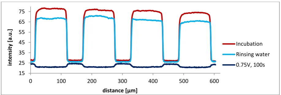
Guest gradient formation on glass with K3IrCl6 as mediator. A CD molecular printboard in between
electrodes was incubated with Fc4-rhodamine and rinsed with water for 1 min. A mediator solution
was placed on top, consisting of 2 mM K3IrCl6 as reductor and 0.1 M K2SO4 as electrolyte. A
potentiostat was used to apply a potential (0.75 V or 0.3 V) to one electrode of the interdigitated electrode array for 100 s. A separate counter electrode was used for all testing experiments.
Guest gradient on glass with FcMeOH as competitor. A CD molecular printboard in between electrodes was incubated with Ad2-rhodamine and rinsed with water for 1 min. A solution of 1 mM
FcMeOH and 0.1 M K2SO4 was placed on top, eventually with 0.6 mM CD. A bipotentiostat was used
to apply 0.47 V and 0.0 V for 3 h to both working electrodes, respectively.
Guest gradient on gold. A CD molecular printboard on gold was incubated with Fc2-rhodamine to
perform cyclic voltammetry. Fluorescence tests were carried out after microcontact printing Fc2
-rhodamine on CD molecular printboard on gold.
Molecular motion experiments. Before spreading could be studied, lines of Ad2-rhodamine were
microcontact printed (Scheme 3.4) on a CD molecular printboard on a glass slide or in between electrodes. PDMS stamps were prepared by casting the precursor poly(dimethylsiloxane) and curing agent at 10:1 volume ratio (total 33 mL) against a silicon master. The air bubbles were removed by vacuum for 30 min. The stamps were cured overnight at 60C. Before microcontact printing, the cut stamps were oxidized by putting them in oxygen plasma (power tuned at 40 mA) for 30 sec. Afterwards, the stamps were inked with 100 µL guest solution (5 µM Ad2-rhodamine in water) for 2
min. The stamps were dried in a stream of nitrogen and brought into conformal contact with the substrate for 1 min. Stamps with 5 μm lines and 25 μm spacing were used. Subsequently, the printed substrate was rinsed with water for 30 sec and imaged by fluorescence microscopy. The stamps were not reused.
Spreading was induced by placing a solution with either 0.6 mM CD (motion Perl) or 0.6 mM CD with 1.0 mM FcMeOH (directed motion) on top of the patterned substrate. Fluorescence images were taken frequently (every 10 min and every 1 min, respectively) for 2 h on the same place of the sample.
Scheme 3.4. Consecutive steps for microcontact printing of fluorescent guest molecules onto a CD monolayer [33]
3.2.3
Characterization methods
Contact angle. Static or dynamic contact angles (θ) were measured with MilliQ water (18.2 MΩ∙cm) on a Krüss G10 Contact Angle Measuring Instrument equipped with a CCD camera. For static measurements, three drops were measured (six data points in total) and averaged to obtain θ. For advancing and receding contact angles, measurements were performed during the growth and shrinkage of a droplet.
Fluorescence microscopy. An Olympus inverted research microscope IX71 was used to record fluorescence microscopy images, equipped with a mercury burner U-RFL-T as light source and a digital Olympus DP70 camera for taking pictures. The fluorescence of the coumarin dye, UV excitation (325 nm ≤ λex ≤ 375 nm) and blue emission (λem 420 nm) was filtered using a Dapi
24
λex ≤ 490 nm) and blue emission (λem 525 nm) was filtered using a U-MWG Olympus filter cube. To
image the fluorescence of a rhodamine dye, green excitation (510 nm ≤ λex ≤ 550 nm) and red
emission (λem 590) was filtered using a U-MWB Olympus filter cube. All fluorescence images were
obtained at room temperature with magnification 10x and iso 800. Intensity profiles were obtained by averaging the images from at least three different places at the surface.
[image:24.595.72.259.420.555.2]Electrochemistry. For gradient formation on glass, an interdigitated electrode array was used. Figure 3.4 shows the design of this array, with gaps of 100 µm and an electrode width of 50 µm. The electrodes consist of platinum on glass substrates, with a titanium adhesion layer. CD monolayers were produced in between the electrodes by using the procedure shown in Scheme 3.3.
Figure 3.4. Design of the interdigitated electrode array used
In one set of experiments (section 5.4, guest gradient on glass with K3IrCl6) an electrochemical cell
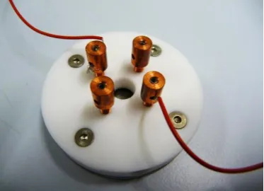
with a volume of 20 mL was used. To scale down the experiment and decrease the amount of solution needed, a Teflon cell was ordered as shown in Figure 3.5. In this case only 400 µL solution is needed and the wires are directly connected to the electrodes which avoids soldering.
Figure 3.5. Picture of the Teflon cell used for electrochemistry
One set of experiments (section 5.4, guest gradient on glass with K3IrCl6) was performed with a
25
All potentials are given relative to a red rod reference electrode (Ag/AgCl, 0.200 V vs. SHE, saturated KCl solution, Radiometer Analytical). All solutions were bubbled with nitrogen beforehand to remove oxygen.
Cyclic voltammograms were recorded in 0.1 M K2SO4 in water or 0.5 M KOH in methanol by normal
staircase voltammetry, at scan rates of 40 or 100 mV/s. Differential pulse voltammetry was performed in guest solutions with 0.1 M K2SO4 between -0.05 V and 0.8 V at an increasing potential
of 2 mV. An amplitude of 40 mV and a pulse width of 0.1 s were used.
Impedance spectroscopy data were obtained in a solution with 1 mM K3Fe(CN)6, 1 mM K4Fe(CN)6 and
0.1 M Na2SO4 starting at 0.21 V with an amplitude of 5 mV using a frequency range from 50 kHz to
26
4
Covalent host gradient formation
This chapter describes the host surface gradient formation by covalent binding. Before motion on these gradients could be tested, the working principle of gradient formation was tested on glass (section 4.1) and gold (section 4.2).
4.1
Host gradient on glass
Scheme 4.1 shows the formation of a CD gradient on glass using click chemistry followed by a Michael addition step. In the first step, coumarin units functionalized with an alkyne group are bound to an azide monolayer on glass via click chemistry. This Cu+-catalyzed cycloaddition reaction is performed in between the electrodes of the interdigitated electrode array to make a surface gradient. Via the reduction and oxidation of Cu2+and Cu+ respectively, a Cu+ gradient is formed in solution. Since the highest amount of Cu+ is formed at the negative electrode, at that side the highest extent of click reaction occur between azide and alkyne groups.
In the second step, the other end of the coumarin molecule is functionalized with heptakis-thio-β-cyclodextrin (CD-(SH)7) via a Michael addition reaction, thus producing a CD surface gradient on top
of the coumarin layer. After step 1, the fluorescence of the coumarin unit is internally quenched by photoinduced electron transfer [35]. After the Michael addition reaction, the quenching is stopped and the fluorescence is restored, because the quenching group is transformed into a non-quenching group. In this way, the formation of the CD gradient can be visualized, assuming that there are no aspecific interactions between CD-(SH)7 and unreacted azide functionalities near the positive
electrode. As a second control step, step 3 includes incubation with a guest, for example Ad2
-rhodamine, which should lead to a surface gradient of guest molecules.
Scheme 4.1. CD gradient formation using 1) click chemistry of a coumarin molecule on an azide monolayer, 2) Michael addition via incubation of CD-(SH)7, and 3) guest incubation
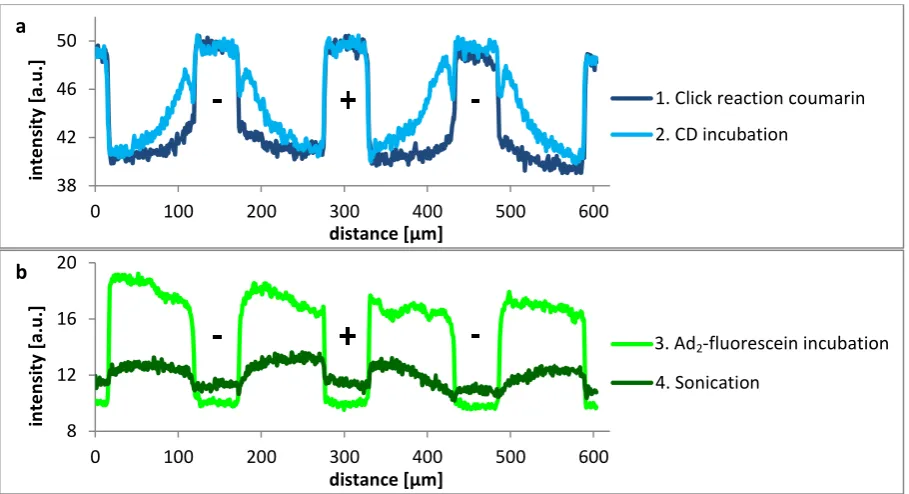
The fluorescence images of the three steps and their intensity profiles are shown in Figure 4.1 and Figure 4.2, respectively. The intensity profiles of the first two steps (Figure 4.2a) are as expected, but incubation of Ad2-fluorescein resulted in a constant intensity profile instead of the desired gradient
27
Figure 4.1. Fluorescence images of the different steps of CD gradient formation, as shown in Scheme 4.1; exposure time 1000 ms
Figure 4.2. Intensity profiles of the different steps of a) CD gradient formation and b) guest incubation and sonication afterwards. The scale of both graphs differs in order to enlarge the fluorescein gradient visible after sonication.
To prevent the physisorption of guest molecules on unreacted azide functionalities, propargyl hexa(ethylene glycol) (HEG-alkyne), consisting of an alkyne group and a long hydrophilic chain, was reacted onto the free azide groups. In this way, the remaining azide groups were replaced by long hydrophilic chains, which should decrease physisorption. This concept was firstly tested by physisorption of guest molecules on a full monolayer of azide groups versus physisorption on a monolayer of HEG-alkyne (Scheme 4.2).
Scheme 4.2. Concept of testing the adhesion resistance of HEG-alkyne on an azide monolayer
The resulting intensity profiles are shown in Figure 4.3, where it should be noted that the exposure time of the sample with HEG-alkyne is four times higher, so the real difference between the two profiles is even larger than the graph shows. In conclusion, the HEG-alkyne layer reduced the physisorption of Ad2-rhodamine with a factor of 14 compared to free azide groups.
38 42 46 50
0 100 200 300 400 500 600
in
te
n
si
ty
[a.u
.]
distance [µm]
1. Click reaction coumarin
2. CD incubation
8 12 16 20
0 100 200 300 400 500 600
in
te
n
si
ty
[a.u
.]
distance [µm]
3. Ad2-fluorescein incubation
4. Sonication
1 2 3
-
+
-100 μm 100 μm 100 μm
b a
[image:27.595.71.526.222.469.2]28
Figure 4.3. Intensity profiles of the different steps of CD gradient formation
The process as shown in Scheme 4.1 was adapted to Scheme 4.3, which includes an extra incubation step with HEG-alkyne.
Scheme 4.3. CD gradient formation using 1) click chemistry of a coumarin molecule on an azide monolayer, 2) Michael addition of CD-(SH)7, 3) HEG-alkyne incubation via click chemistry to prevent
physisorption on unreacted azide moieties and 4) guest (Ad2-rhodamine) incubation
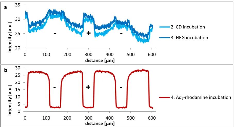
[image:28.595.70.525.491.739.2]As can be seen in Figure 4.4, the HEG incubation step does not strongly influence the intensity profile of the coumarin molecule. After the fourth step, the guest gradient is clearly visible, even without sonication, but the direction is still wrong and the intensity is still very high for the region where HEG-alkyne should prevent interactions between azide groups and Ad2-rhodamine.
Figure 4.4. Intensity profiles of a) steps 2-3 of CD gradient formation including HEG-alkyne incubation and b) guest incubation. The scale of both graphs differs in order to enlarge the coumarin gradients.
0 10 20 30 40 50
0 200 400 600
in te n si ty [a.u .] distance [µm]
Azide - Ad2-rhodamine
Azide - HEG - Ad2-rhodamine
20 25 30 35
0 100 200 300 400 500 600
in te n si ty [a.u .] distance [µm]
2. CD incubation
3. HEG incubation
0 5 10 15 20 25 30
0 100 200 300 400 500 600
in te n si ty [a.u .] distance [µm]
4. Ad2-rhodamine incubation
125 ms
500 ms
b a
Azide - Ad2-rhodamine
Azide - HEG - Ad2-rhodamine
29
Next, a HEG layer was introduced as a gradient instead of the incubation step by exchanging the positive and negative electrode and making a new Cu+ solution gradient. Incubation of Ad2
-rhodamine did not result in gradient formation, also not after short (30 s) incubation in water or a 10 mM CD solution. Only incubation in a CD solution for 3.5 h decreased the intensity a little bit, but the intensity profile was still flat in between the electrodes.
It is difficult to explain the wrong direction of the guest gradient. The density of CD molecules close to the negative electrode might be low, for example due to a low density of coumarin molecules. If the CD density is too low, the Ad2-rhodamine molecules might have monovalent interactions with CD
instead of divalent and can thus be easily desorbed by rinsing. If this is true, it should be possible to backfill the empty CD molecules with Ad2-fluorescein. However, no fluorescence of fluorescein could
be observed, even though the sample was rinsed for only a few seconds to prevent immediate desorption.
To prevent physisorption of Ad2-rhodamine and promote supramolecular interactions only, a
solution of 1 mM HEG-Ad and 1 µM Ad2-rhodamine was incubated in the fourth step. It is assumed
that HEG-Ad interacts in the same aspecific way as Ad2-rhodamine did in the previous experiments.
Since HEG-Ad does not contain a dye, these physisorbed molecules are not visible. With respect to supramolecular interactions, Ad2-rhodamine binds much stronger than the monovalent HEG-Ad due
to its multivalency. So Ad2-rhodamine is a strong competitor compared to HEG-Ad, but only near the
negative electrode where supramolecular interactions with CD are possible.
The fluorescence image and intensity profile after incubation with HEG-Ad and Ad2-rhodamine
(Figure 4.5) show a very clear gradient, but still in the wrong direction. While HEG-Ad should promote supramolecular interactions at the negative electrode, the gradient is much steeper than in Figure 4.4, thus indicating even less interactions between Ad2-rhodamine and the CD gradient.
Figure 4.5. (a) Fluorescence image after incubation with HEG-Ad and Ad2-rhodamine in step 4;
exposure time 500 ms; (b) intensity profile of the fluorescence image
It is still unexplained why the guest gradient is formed in the wrong direction and the measured fluorescence of the guest molecules is so high near the positive electrode. An explanation might include the interaction of CD molecules with unreacted azide groups in step 2. Although this is very unlikely, it is worthwhile to switch step 2 and 3.
4.2
Host gradient on gold
Scheme 4.4 shows the proposed design for host gradient formation on gold. It was desired to desorb the CD heptathioether molecules by reduction, but thioether molecules cannot be reduced by gold [43]. However, thiol functionalized molecules are often used for reductive desorption [43, 44], so it would be useful to have CD molecules coupled to a long linker with thiol end groups. Since this
0 5 10 15 20 25
0 200 400 600
in
te
n
si
ty
[a.u
.]
distance [µm]
-
+
-a b
-
+
30
molecule was not available, the system was based on the indirect formation of a CD gradient. The substrate is firstly incubated with an alkanethiol, which can be desorbed by reduction. When an in-plane potential gradient is applied to the gold substrate, the thiol groups are reduced at one electrode and thus desorb, while they remain adsorbed near the oxidizing potential, thus creating a surface gradient [45]. The shown potentials are only indicative values, since the reduction potential strongly varies for different alkyl lengths [44]. The surface can be backfilled with CD heptathioether, which forms a surface gradient in the opposite direction. This gradient can be visualized by incubation with guest molecules, when gold does not quench the fluorescence of the guest molecules.
Scheme 4.4. CD gradient formation using 1) adsorption of an alkanethiol onto a gold substrate, 2) reductive desorption of thiol groups via an in-plane potential gradient, 3) backfilling with CD heptathioether and 4) fluorescent guest (Ad2-rhodamine) incubation
The first steps have been tested already. At first, the desorption of a full monolayer of 1-hexadecanethiol was tested. This resulted in the cyclic voltammogram shown in Figure 4.6, where reductive desorption of the thiol groups can be observed around -0.85 V. The contact angle decreased from 111° to 44° during this step, which proves that the thiol molecules were desorbed. When the sample was backfilled with 16-mercaptohexadecanoic acid, the contact angle decreased even further to 21°, due its hydrophilic head group.
Figure 4.6. Cyclic voltammogram of a full monolayer of 1-hexadecanethiol on gold with 0.5 M KOH in methanol on top, measured at 100 mV/s
Therefore, the experiments were extended to the used of an in-plane potential gradient. A SAM of 1-hexadecanethiol was used, which was partly desorbed by applying a potential of -0.4 V and -1.8 V for 60 s on both sides of the gold substrate, respectively. The sample was backfilled with 16-mercaptohexadecanoic acid, which has a hydrophilic head group in contrary to 1-hexadecanethiol. Therefore, the higher the surface concentration of 1-hexadecanethiol, the higher
-0.5 -0.4 -0.3 -0.2 -0.1 0.0
-1.4 -1.2 -1 -0.8 -0.6 -0.4
I [
m
A
]
31
the hydrophobicity. This hydrophobicity gradient could be observed by contact angle measurements (Figure 4.7). The contact angle varied between 44° and 99° over approximately 1 cm, with further optimization possibilities. These results confirm the working principle of the alkanethiol gradient formation on the surface and are thus promising for step 3 and 4. However, these steps were not performed due to scarcity of CD heptathioether within MnF.
Figure 4.7. Hydrophobicity gradient after reductive thiol desorption visualized by contact angle measurements
4.3
Summary
A covalent host surface gradient on glass was fabricated via click chemistry, which could be visualized by fluorescence spectroscopy. However, incubation with guest molecules led to a gradient in the wrong direction, which has to be further investigated.
32
5
Non-covalent guest gradient formation
In contrast to the previous chapter, non-covalent interactions are described in this chapter for the formation of a guest surface gradient, which provides more tunability since the direction of the gradient could be switched, for example. A surface gradient of guest molecules automatically includes an opposite gradient of free host molecules, which could direct the motion of molecules. Before motion could be tested, the working principle of gradient formation was tested by the production of static surface gradients in guest molecules. Electrochemically active ferrocene-functionalized guest molecules (section 5.1) and CD molecular printboards on glass (section 5.2) were firstly characterized. The guest molecules were used to design gradient formation systems on CD printboards on glass (section 5.3 through 5.5) and gold (section 5.6).
5.1
Ferrocene-functionalized guest molecules
5.1.1
Synthesis of Fc
4-rhodamine
Ferrocene-functionalized guest molecules are electrochemically active, since oxidation of this species ensures loss of its supramolecular interactions with a CD printboard [19]. In this way, the guest molecules desorb from the surface after oxidation. A new guest molecule was designed, as shown in Figure 5.1. The molecule Fc4-rhodamine is based on a second-generation dendrimer, has four
ferrocene groups at its periphery and a fluorescent rhodamine group in the focal point in order to make the guest molecule visible.
Since the guest molecules are meant to be desorbed by electrochemistry instead of competition or complexation, strong supramolecular interactions with the CD layer were necessary. Therefore, tetravalent interactions were chosen, which also increases the stability of the supramolecular system (Fc:CD = 1:1). Long tetraethylene glycol spacers were used to ensure enough flexibility to interact with four host molecules at once. Section 5.4 explains the desired application of Fc4-rhodamine into a
[image:32.595.76.286.471.680.2]gradient formation process.
Figure 5.1. Fluorescent ferrocene-functionalized guest molecule Fc4-rhodamine
The synthesis route for Fc4-rhodamine 6 is shown in Scheme 5.1 below. The synthesis started with a
33
which reacts in ratio 1:2 with molecule 3. The protective t-Boc (tert-butyloxycarbonyl) group from the resulting molecule 4 was removed by using TFA, giving the free amine 5. Finally, this amine was reacted with the fluorescent dye lissamine rhodamine B sulfonylchloride to result in the desired product 6.
Scheme 5.1. Synthesis route towards the fluorescent ferrocene-functionalized guest molecule 6: i. 3,5-diethynylaniline, Cu(CH3CN)4PF6, TBTA, CH2Cl2/MeOH, r.t., 24 h; ii. a. saturated NaHCO3, CH2Cl2,
0 °C, 5 min, b. CSCl2, r.t., 45 min; iii. tert-butyl (6-(bis(3-aminopropyl)amino)hexyl)carbamate, CH2Cl2,
r.t., o.n.; iv. TFA, CH2Cl2, 0 °C, 1 h; v. lissamine rhodamine B sulfonylchloride (mixture of isomers),
DIPEA, CH2Cl2, r.t., o.n.
The yield of the different steps is shown in Scheme 5.1. The overall yield is about 4%, which is mainly due to the low yield of the last step, since it is quite difficult to couple the dye to 5 and purify the resulting product. The synthesis of Fc4-rhodamine was confirmed by NMR spectroscopy and mass
spectroscopy (Appendix A). UV/Vis spectroscopy (Appendix A) and fluorescence spectroscopy were performed to investigate the properties of the new compound.
The excitation and emission spectra of Fc4-rhodamine, as shown in Figure 5.2, were measured by
fluorescence spectroscopy. As a comparison, excitation and emission spectra were recorded of the pure dye (lissamine rhodamine B sulfonylchloride, also 1 μM) in water. The dye has maximal fluorescence excitation at 565 nm light and maximal fluorescence emission at 580 nm light. The emission and excitation profiles of the dye and Fc4-rhodamine are comparable to each other and to
34
Figure 5.2. Excitation and emission spectra of Fc4-rhodamine (1 µM in water, 0.5% MeOH, pH
neutral) and of the pure dye (lissamine rhodamine B sulfonylchloride, 1 µM in water). The mentioned slit values equal to the emission slit.
When the same parameters were used in fluorescence spectroscopy, the measured maximum intensity of Fc4-rhodamine was only 11% of the maximum fluorescence of the pure dye. This could be
due to the poor solubility of Fc4-rhodamine, but also quenching by the Fc groups of Fc4-rhodamine
could occur. This is confirmed by the observation that the maximum fluorescence of a solution with 0.5 µM pure dye and 5 µM Fc4-rhodamine was 25% lower than that of a solution with only 0.5 µM
pure dye, although the intensity should increase. The quenching effect was not further investigated, since the fluorescence was still high enough for visualization purposes.
To test the supramolecular interactions of Fc4-rhodamine, CD monolayers were incubated with a
1 µM solution of Fc4-rhodamine in water. The sample was rinsed with water and imaged with
fluorescence microscopy, showing that the incubation was successful. The sample was consecutively rinsed with 10 mM CD in water, rinsed with 1% MeOH in water, and finally sonicated. The intensity did not change significantly after these steps, thus indicating a strong interaction between Fc4
-rhodamine and the substrate.
5.1.2
Electrochemistry
Next to the tetravalent guest molecule described in section 5.1.1, the already available Fc2
-rhodamine was used. The detection limit of cyclic voltammetry was too high (100 μM [47]) to measure the oxidation and reduction peaks of these guest molecules in water (5 μM). The guest concentration could not be increased due to poor solubility. Therefore, differential pulse voltammetry (DPV) was used, which has a detection limit of 10 nM under optimal conditions [47]. However, Fc4-rhodamine (1 μM) was still not detectable with DPV. This might be due to the poor
solubility of Fc4-rhodamine, which induces precipitation of the guest molecules and thus a lower
concentration than the desired 1 µM.
The differential pulse voltammogram of Fc2-rhodamine is shown in Figure 5.3. A new peak arises at
0.43 V after adding the guest, which can thus be attributed to the oxidation and reduction of ferrocene. The peak position equals to Emax and can be used to calculate E1/2:
[47], so E1/2 = 0.45 V (ΔEp = amplitude = 40 mV). The Fc dendrimers used by Nijhuis are comparable in both
structure and E1/2 (0.50 V [25]). When an ideal peak separation of 57 mV is assumed, Fc2-rhodamine
is reduced at 0.42 V and oxidized at 0.48 V.
0 100 200 300 400 500 600
450 500 550 600 650
in te n si ty [a.u .] wavelength [nm]
excitation 1 μM Fc4-rhodamine (emission at 580 nm, slit 5 nm)
emission 1 μM Fc4-rhodamine (excitation at 565 nm, slit 8 nm)
excitation 1 μM pure dye (emission at 580 nm, slit 2.5 nm)
emission 1 μM pure dye
(excitation at 565 nm, slit 2.5 nm) excitation 1 μM Fc4-rhodamine
(emission at 580 nm, slit 5 nm)
emission 1 μM Fc4-rhodamine
[image:34.595.71.524.70.203.2]35
Figure 5.3. Differential pulse voltammogram of Fc2-rhodamine (5 μM, 5% MeOH in water with 0.1 M
K2SO4) and the same solution without guest as a blank; the amplitude was 40 mV.
5.2
Characterization of CD molecular printboard on glass
CD molecular printboards were synthesized on glass by a method developed by MnF [20]. Supramolecular interactions between the CD monolayer and guest molecules were tested by competition with CD in solution (10 mM in water, 4.5 h, four times refreshing). Extensive research has already been performed on competition with CD in solution for the adamantyl (Ad)-functionalized guests [16, 20]. The guest molecules used were Ad2-rhodamine, Ad3-rhodamine and
Fc4-rhodamine, whose results are shown in Figure 5.4. The shown intensity profiles consist of
horizontal cross sections of pictures from the fluorescence microscope. The profiles are as expected, since the intensity is high in between the electrodes, and low on the electrodes where the guest molecules should not adsorb and the light is blocked by the Pt electrodes. The profiles were calculated by averaging three different places at the sample.
There are two trends for the different guest molecules. At first, the higher the multivalency, the higher the increase after the extra rinsing step with water. This observation cannot be explained, since it is unknown what happens after another extra rinsing step with water. These experiments were performed once, so no hard conclusions can be drawn.
The other trend is visible in the remaining intensity after incubation with CD in solution. If the remaining intensity is expressed as a percentage of the intensity after rinsing with water, the leftover is higher when the multivalency becomes higher. This is logical, since a higher multivalency induces stronger interactions in general, which can be applied directly to compare the divalent and trivalent guests to each other. However, the intrinsic binding constant of the adamantyl-CD interaction equals to 5.7∙104 M-1, which is stronger than th
![Figure 2.4. Overview of different properties surface gradients [13]](https://thumb-us.123doks.com/thumbv2/123dok_us/1187115.641874/10.595.69.448.82.378/figure-overview-different-properties-surface-gradients.webp)