Volume 6, Issue 11, November 2017, ISSN: 2278 -7798
Effect of Welding Parameters on the Strength of Butt Weld Joint using TIG Welding
Nerella. Kranthi Teja1, Dr. B. Amar Nagendram2
1Post Graduate student, Department of Mechanical Engineering (M. Tech. Machine Design), DMS SVH College of Engineering, Machilipatnam, Andhra Pradesh, India.
2Professor, Department of Mechanical Engineering , DMS SVH College of Engineering, Machilipatnam, Andhra Pradesh, India.
Abstract: - One of the most effective metal joining process is welding which involves joining of two or more similar or different materials by heating to plastic state. Welding strength is an important parameter in all metal joints used in industrial applications. It is mostly used in industrial applications, in fabrication, maintenance and repair of parts.
In this thesis for V-groove butt weld joint the tensile strength is find out by varying welding speed and included angle. For V-groove geometry plates with included angles from 350, 450 and 500will be made from structural steel (A633 Grade E) by using TIG welding process. Welding speeds used for the experimentation are 0.4 cm/sec, 0.8 cm/sec and 1.20cm/sec.
Optimization of ultimate tensile strength is done by using Minitab software by designing Taguchi parameter orthogonal array.
Index Terms: - TIG welding, included angle, welding speed, Butt weld joint, and Tensile strength.
1. INTRODUCTION
Welding is simply a method of bonding two pieces of metal. While there are other methods to join metals (brazing, riveting and soldering, for instance), welding is a method of choice for its efficiency, strength and versatility.
TIG welding is preferred over other methods.
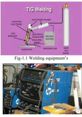
1.1. TIG Welding: -
TIG welding stands for Tungsten Inert Gas welding and is technically called as Gas Tungsten Arc Welding or GTAW. The process uses a non-consumable tungsten electrode that delivers current to the welding arc.
Inert gas argon is used to protect and cool the tungsten and weld puddle. TIG welding is identical to the oxy-acetylene gas welding which uses a filler material for build-up or reinforcement. TIG welding is often mentioned as the Heli arc welding, originating from an early Hobart "Heli-Arc"
machine. The name comes because of using helium gas for shielding the electric arc. TIG welding was developed in the 1930s and used during II World War as the preferred method for welding the aircraft parts. Earlier, some alloy steels and aluminum were welded with a torch, which requires significant skill and time, while TIG welding made that ease. Fig-1.1 and 1.2 shows the TIG welding set up.
Fig-1.1 Welding equipment’s
Fig- 1.2 TIG welding machine
The TIG process setup consists of an electric torch and a filler rod for feeding into the molten puddle. The capability to soft start and soft stop the heat makes the TIG process different from other types of welding processes.
Some people uses the accelerator pedal to control the heat if they are working on a bench and others like fingertip remotes on the torch if they are working in areas that are considered out of position. Remote can be used for adjusting the heat while welding.
1.2. Welding joint:-
Two or more pieces of metal or plastic are joined together is known as a joint which may be point or edge.
The joints are prepared by welding two or more pieces of metal or plastic for a particular geometry. According to American Welding Society there are five types of joints such as butt, lap, corner, edge, and tee joints. At the joint where actual welding takes place may have different
configuration. Butt weld joint is preferred over other joints for the experimentation.
Butt welds:-
In butt weld joints two pieces of metal to be joined are in the same plane. They require only some preparation and can be used for thin sheet metals which can be welded with single pass. Least amount of welding material possible should be used for obtaining strong welds. Butt welds are preferred in automated welding processes for its ease of preparation. When metals are being welded in the absence
of human guidance, there will
be no operator for making adjustments in case of non-ideal joint preparation. Because of this possibility, butt welds are utilized for their simplistic design to feed through automated welding machines efficiently.
1.3. The Taguchi Philosophy–Robust Design:-
Taguchi Design of Experiments:
For making a new product many factors and input variables should be taken into consideration. The Taguchi philosophy is a best approach for defining the finest combination of inputs to produce a product or service using the Design of Experiments (DOE) methodology for determining parameter levels. DOE is an essential tool for designing the processes and products. This is a method for categorizing the accurate inputs and parameter levels for designing a good quality products or services. Taguchi method approaches to get a robust design.
• Robust design can be achieved by the following three methods
– Concept design – Parameter design – Tolerance design
We focus on Parameter design for experimentation.
A. Parameter Design:-
It consists of selecting the Control factors/parameters and their “optimal”
levels. The objective is to make the design Robust!
Control factors are the process variables which influences the management. Such as procedures used and the type and amount of training required.
There is a complex relationship between the design/product performance and control factors.
The best parameter levels can be find out by experimentation.
2. OBJECTIVE OF THE WORK In this thesis, materials with V-groove geometry different models of plate with various included angles from 350, 450and 500will be made from structural steel (A633 Grade E). Different welding speeds 0.4 cm/sec, 0.8 cm/sec and 1.20 cm/sec are used to prepare a V-groove butt weld joint using TIG welding. Effect of welding parameters on the tensile strength of weld joint will be analyzed.
3. EXPERIMENTAL PROCEDURE 3.1. Material:-
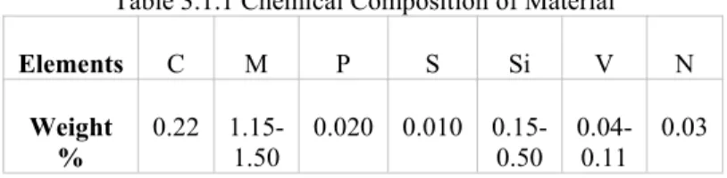
Material used for the preparation of plates is structural steel A633 (Grade E).The chemical composition of the material is given in the table
Table 3.1.1 Chemical Composition of Material
Elements C M P S Si V N
Weight
% 0.22 1.15-
1.50 0.020 0.010 0.15- 0.50 0.04-
0.11 0.03 3.2. Preparation of welding joints:-
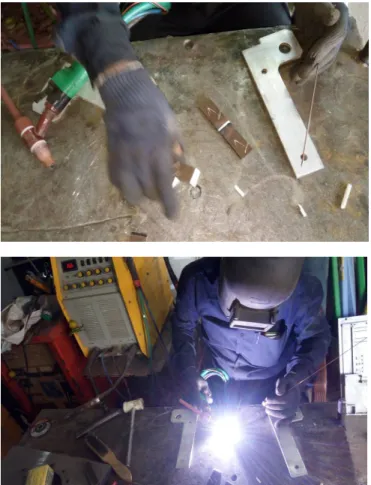
Different models of V-Groove butt weld joints are prepared by using TIG welding by varying the welding parameters.
Experimentation images:-
Fig:
3.2.1&3.2.2 Work Pieces
Volume 6, Issue 11, November 2017, ISSN: 2278 -7798
Fig: 3.2.3&3.2.4 welding process
Fig: 3.2.5 Finished welding components
3.3. Experimentation:-
Tensile test is done on welded metal joints to find out the ultimate tensile strength. The values obtained from the tensile test are optimized by using Minitab software which involves designing of Taguchi orthogonal array. For the experiment welding parameters selected are shown in table: 3.3.1 and Taguchi orthogonal array is shown in Table:
3.3.2.
Table: 3.3.1 Welding Parameters
Table: 3.3.2 Taguchi Orthogonal Array PROCESS
PARAMETERS LEVEL1 LEVEL2 LEVEL3 WELDING SPEED
( cm/s) 0.4 0.8 1.20
GROOVE
ANGLE(0) 35 45 50
GROOVE ANGLE
(0) WELDING SPEED ( cm/s)
35 0.4
35 0.8
35 1.2
45 0.4
45 0.8
45 1.2
50 0.4
50 0.8
50 1.2
Observations:-
Observations are recorded by running the experiments.
Observed ultimate tensile strengths are given in the Table:
3.3.3.
Table: 3.3.3 Observations
3.4. Optimization of Ultimate Tensile Strength using Minitab Software:-
Design of Orthogonal Array:
First Taguchi Orthogonal Array is designed in Minitab17 to calculate S/N ratio and Means which steps is given below:-
Fig: 3.4.1
Factors:-
Fig: 3.4.2
Fig: 3.4.3
Optimization of Parameters:-
Fig: 3.4.4 GROOVE
ANGLE(0)
WELDING SPEED
( cm/s)
ULTIMATE TENSILE STRENGTH
(MPa)
35 0.4 375
35 0.8 410
35 1.2 451.197
45 0.4 403
45 0.8 440.581
45 1.2 372
50 0.4 375.287
50 0.8 369
50 1.2 378
Volume 6, Issue 11, November 2017, ISSN: 2278 -7798
Fig: 3.4.5
Fig: 3.4.5
Analyze Taguchi Design – Select Responses
Fig: 3.4.6
Terms:
Fi g: 3.4.7
Taguchi method aims on using the signal–to–noise (S/N) ratio such that we can find better responses which enables us to reduce the quality characteristic variation caused by uncontrollable parameters. The tensile strength is considered as the quality characteristic with the concept of
"the larger-the-better". For S/N ratio the larger-the-better is:
S/N = -10 *log (Σ (1/n)*(1/Y2))
Where n is the number of measurements in a trial/row, in this case, n=1 and y is the measured value in a run/row. The S/N ratio values are calculated by taking into consideration above Eqn. and by using Minitab 17 software.
Final output values
Fig: 3.4.8
4. RESULTS
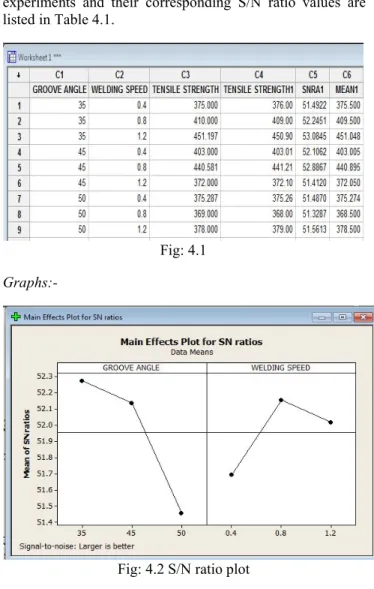
The tensile strength values measured from the experiments and their corresponding S/N ratio values are listed in Table 4.1.
Fig: 4.1 Graphs:-
Fig: 4.2 S/N ratio plot
Fig: 4.3 Means plot
Table: 4.1. S/N Ratio larger the better for tensile strength mean response table
Level No. Groove Angle Welding Speed
Level 1 52.28 51.71
Level 2 52.14 52.19
Level 3 51.46 52.02
From the table we can observe tensile strength is greater when maintaining the groove angle at 350, and welding speed 1.20 cm/sec according to the signal to noise ratio. We can find the used parameters are optimum for the experimentation.
5. CONCLUSION
The experiment designed by Taguchi method fulfills the desired objective. Fuzzy interference system has been used to find out the ultimate tensile strength .The all possible values have been calculated by using MINITAB 17 software. Analysis of variance (ANOVA) helps to find out the significance level of the each parameter. The optimum value was find out by using MINITAB-17 software.
The welding parameters are welding speed, and groove angle for TIG welding of work piece steel. In this work, the optimal parameters of welding speed are 0.4 cm/s, 0.8 cm/s and 1.20 cm/s, groove angle 350, 450, 500. Experimental work is conducted by considering the above parameters. Ultimate tensile strength validated experimentally.
The experimental results are confirming the validity of used Taguchi method for obtaining the welding performance and optimizing the welding parameters in TIG welding at welding speed 1.20 cm/s, and groove angle 350.
6. ACKNOWLEDGEMENT
I would like to express my sincere thanks to my guide Dr. B. Amar Nagendram for his guidance, thoughtful suggestions and moral support. I wish to express my thanks to principal Dr. D.Srinivasa Rao and Head of the Mechanical Department Sri T. Ravi Kumar. I would like to acknowledge the support of Department of Mechanical engineering DMS SVH College of engineering, Machilipatnam, Andhra Pradesh, India.
Volume 6, Issue 11, November 2017, ISSN: 2278 -7798
7. REFERENCES
[1] N.S. Rajkumar, Srihari, “A study of effect of groove angle on angular distortion& impact strength in butt weld”, International conference on mechanical engineering, December,2001.
[2] N.Ren, M.Zan, “Constructing effect of weld & heat affected zone on deformation behavior of welded tubes in numerical control bending process”, Journal on material processing technology(2012)
[3] Rossi, E. Boniface, “Welding engineering”, Mc Grow- Hill Book company New York,2012.
[4] I. Sattari-Far, M.R Farahani, “Effect on weld groove shape& pass number on residual stresses in butt weld pipes”, International journal of pressure vessel & piping (2009)
[5] D.Akbari, I. Sattari-Far, “Effect of welding heat input on residual stresses in butt weld of dissimilar pipe joints”, International journal of pressure vessel & piping (2009) [6] T. H. Hyde, J. A. Williams, W. Sun, “Factors, Defined from Analysis, Contributing to the Creep Performance of Weld Repairs”, Creep Performance of Weld Repairs OMMI (Vol. 1, Issue 3) December 2002.
[7] T. H. Hyde, J. A. Williams, A. A. Becker,W. Sun, “A review of the finite element analysis of repaired welds under creep conditions”, Review of FE analysis of repaired welds OMMI (Vol. 2, Issue 2) Aug. 2003.
[8] Tseng, K. H., & Hsu, C. Y. (2011). Performance of activated TIG process in austenitic stainless steel welds.
Journal of Materials Processing Technology, 211(3), 503- 512. [9] Narang, H. K., Singh, U. P., Mahapatra, M. M., &
Jha, P. K. (2011). Prediction of the weld pool geometry of TIG arc welding by using fuzzy logic controller.
International Journal of Engineering, Science and Technology, 3(9), 77-85.
8. AUTHORS BIOGRAPHY
Nerella. Kranthi Teja Post Graduate student, Department of Mechanical Engineering (M. Tech.
Machine Design), DMS SVH College of
Engineering, Machilipatnam, Andhra Pradesh, India.
Dr. B. Amar Nagendram Professor, Department of Mechanical Engineering , DMS SVH College of Engineering, Machilipatnam, Andhra Pradesh, India.