This paper is a postprint of a paper submitted to and accepted for publication in IET
Optoelectronics and is subject to Institution of Engineering and Technology Copyright. The copy of record is available at IET Digital Library
Performance Evaluation of Digital Pulse Position Modulation for WDM
FSO Systems Impaired by Interchannel Crosstalk
†A.M. Mbah, J.G. Walker, A.J. Phillips
Division of Electrical Systems and Optics, Faculty of Engineering, University of Nottingham,
University Park, Nottingham NG7 2RD, UK
†Corresponding author’s email: [email protected]
Tel: +44 (0) 115 846 6708, Fax: +44 (0) 115 951 5616
Abstract
Wavelength division multiplexing (WDM) has been proposed for fibre, intersatellite, free space
and indoor optical communication systems. Digital pulse position modulation (DPPM) is a
more power efficient modulation format than on-off keying (OOK) and a strong contender for
the modulation of free space systems. While DPPM obtains this advantage in exchange for a
bandwidth expansion WDM systems using it are still potentially attractive, particularly for
moderate coding levels. However WDM systems are susceptible to interchannel crosstalk and
modelling this in a WDM DPPM system is necessary. Models of varying complexity, based on
simplifying assumptions, are presented and evaluated for the case of a single crosstalk
wavelength. For a single crosstalk, results can be straightforwardly obtained by artificially
imposing the computationally convenient constraint that frames (and thus slots also) align
cases of modest coding level, and using both simulation and analytical methods. In general,
DPPM maintains its sensitivity advantage over OOK even in the presence of crosstalk while
predicting lower power penalty at low coding level in WDM systems.
1 Introduction
Digital pulse position modulation (DPPM) is well known to be an attractive modulation format
in free space optical communications (whether intersatellite, atmospheric or indoor wireless)
[1-3]. Apart from the power efficiency advantage there is the additional advantage in some
schemes, like the one considered here, that there is no need to set and track a decision threshold
[4, 5]. DPPM is particularly attractive over this channel relative to a fibre channel (which has
been proposed and intensively investigated [6, 7]), because the channel is dispersion free [1].
The advantages of DPPM however do come at the expense of a bandwidth expansion.
With the continuous increase in demand for bandwidth, wavelength division multiplexing
(WDM) systems have been investigated and/or deployed for fibre, free space and wireless
optical networks [8-10]. Multi-user access network scenarios may also be served by WDM, for
example WDM passive optical network (PON) is generally considered as a good solution to
the bandwidth requirement for future access networks, with potential for higher data rate,
improved data security and longer reach [8, 11]. The drivers for WDM deployment remain the
same whether the modulation format is conventional on off keying (OOK) or DPPM (as long
as the bandwidth expansion can be incorporated). Although the improvement in receiver
sensitivity comes at the expense of bandwidth, with a moderately low coding level, DPPM can
combine with most multiplexing/multiple access schemes and other modulation techniques
without considerable bandwidth expansion. For example, some variants and hybrids of DPPM
proposed for point-to-point fibre communication systems [12, 13]. WDM systems using DPPM
have been studied in [14-17]. However, once there are multiple wavelengths in a
communication link, imperfect optical components (e.g. demultiplexers, filters, etc. [18, 19])
and possibly asymmetric loss necessitate the evaluation of the impact of interchannel crosstalk
[20, 21]. This is well known for OOK; crosstalk in WDM OOK systems has been investigated
for fibre, intersatellite and wireless links [18, 20, 22-24]. However, such a performance
evaluation for DPPM interchannel crosstalk has not yet been provided (for any of the realistic
WDM DPPM scenarios whether intersatellite, atmospheric, indoor, multi-user, PON or point
to point). This paper is intended to remedy this shortfall. It should be noted that necessarily this
evaluation is somewhat more complex than the equivalent for OOK.
Specifically in this paper, the evaluation of an optically preamplified WDM DPPM wireless
system impaired by interchannel crosstalk is performed. The presence of an optical amplifier
(OA) further improves the receiver sensitivity, but introduces amplified spontaneous emission
(ASE) noise. The ASE noise beats with the signal and itself to produce signal-spontaneous and
spontaneous-spontaneous beat noises which degrade the system performance. Established bit
error rate (BER) evaluation techniques including the Gaussian approximation (GA), Chernoff
bound (CB) and modified Chernoff bound (MCB) are applied in the analysis. While the GA
uses only means and variances to describe the signal and noise, the CB and MCB use the
moment generating function (MGF) which gives a full statistical description of the signal and
noise [7]. Results obtained analytically (and in the case of multiple crosstalk verified with
Monte Carlo simulations) are compared with WDM OOK results and presented. However
experimental verification would be necessary for full system characterization. A foreseeable
issue in experimentation is the complexity involved in symbol synchronization, and a possible
2 Optically Preamplified WDM DPPM receiver
In DPPM signal transmission format, a frame of duration equal to MT b is divided into M
n 2
equal time slots of length ts MTb n, where M is the coding level and equal to the number of
data bits transmitted per DPPM frame and Tb 1 Rb is the equivalent OOK NRZ bit period,
where Rb is the bit rate. The maximum likelihood detection receiver is preferred for the best
performance in DPPM optical wireless systems [1]. Circuitry is required to integrate over each
slot in a frame and the decision is made by comparing the results and selecting the slot with the
largest signal as the pulse position [4].
A general WDM DPPM system that might require evaluation of crosstalk impact could include
a fibre or free space (or hybrid) channels and may be in a point-to-point, multipoint-to-point or
PON configuration. Different sources and levels of crosstalk could arise in a WDM DPPM
system depending on the link configuration. In most point-to-point systems with all signal
wavelengths originating from the same place, the major source of crosstalk is imperfect optical
bandpass filter (OBPF)/demultiplexer (demux) rejection and since most realistic systems will
employ OBPF/demux with good rejection ratio, unless there is a power drop in the signal
wavelength compared to the interfering wavelengths (or some relative spectral shift of
passband and signal), the crosstalk level will be fairly small. This is also the case in
point-to-multipoint fibre systems (like WDM PON downstream) with all signal wavelengths originating
from the same place. But in multipoint-to-point links such as upstream transmission in hybrid
fibre and FSO systems or in PON (where signals could experience asymmetric splitting loss,
fibre and/or FSO attenuation, beam spreading and coupling loss), signals at different
wavelengths will arrive at the OBPF/demux at different power levels. Under this condition, the
crosstalk in the system is no longer dependent only on the OBPF/demux channel rejection but
wavelengths and the desired wavelength at the input of the optical filter. Other cases where
asymmetry could affect the level of crosstalk include point-to-multipoint systems with signal
wavelengths having different powers prior to multiplexing.
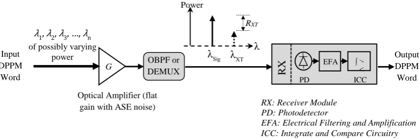
A generic system structure which could be easily adapted to all the different scenarios above
is shown in Fig. 1. DPPM signals from different wavelengths are multiplexed and transmitted
over a wireless/free-space link to a receiving lens. They could also in principle arise from
different physical locations as long as they can be collected and coupled effectively into the
optical amplifier (OA) which is done by collimating them into a short fibre length at the
amplifier input before being demultiplexed into different wavelengths for detection by a PIN
photodiode. The optical preamplifier is just treated as a linear gain block generating noise as
in Fig. 1. Thus saturation based effects, and other nonlinearities, that may justify a more
sophisticated treatment to include the contribution of certain optical amplifiers to the overall
crosstalk at the receiver, are not incorporated. The demux/OBPF provides an effective optical
bandpass filtering which helps to reduce the ASE noise prior to photodetection, and the
detected signal is passed through electrical filtering and amplification before integrate and
compare circuitry is used to decide which DPPM slot contains the signal pulse. Finally, the M
[image:5.595.86.514.566.708.2]bit word corresponding to the chosen slot is selected as the receiver output.
Fig. 1: Generic system structure for optically preamplified WDM DPPM receiver Optical Amplifier (flat
gain with ASE noise) Input
DPPM Word
λ1, λ2, λ3, …, λn
of possibly varying power
G
λ λSig λXT
RXT
Power
OBPF or DEMUX
Output DPPM Word
EFA
PD
> < ∫
ICC
RX
RX: Receiver Module PD: Photodetector
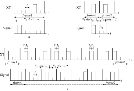
3 Crosstalk Modelling
The analysis of crosstalk in a DPPM system requires some consideration to ensure that the
different scenarios that could arise during frame reception are taken into account. For example,
there may be assumed (and it is stressed that this is generally for mathematical convenience)
an alignment of frames (and evidently slots) (FA) or only slots (OSA) between the signal and
crosstalk (XT) as shown in Figs. 2a and 2b respectively. However, in a practical system, it is
more likely that there is a misalignment of slots (SM) (and evidently frames) between signal
and crosstalk during signal reception (see Fig. 2c). In Fig. 2, n1,n2ℤ (integer) are the number
of whole slots in the earlier and later transmitted crosstalk frames respectively that overlap the
signal frame under consideration, while t1 (or t2) is the slot offset between the slots in a
particular signal frame and the slots in the earlier (or later) transmitted crosstalk frame that
overlap with the signal frame , also t2 ts t1. Thus both t1 and t2 define the fractional or
partial crosstalk that could affect the signal slots. Furthermore, in the case of both OSA and
SM there is the possibility in some systems that the misalignment is maintained for a long time
period and thus performance would be calculated for the specific misalignment. Equally in
many realistic systems the misalignment will change sufficiently frequently that the proper
Fig. 2: Illustration of crosstalk in WDM DPPM receiver (a) Frames aligned (FA) for M = 3, (b)
Only slots aligned (OSA) for M = 2 and (c) Slots (and frames) misaligned (SM) for M = 2
frame1
Signal
XT ts
a
frame1
ts
frame2
Signal XT
b
ts
Signal
frame1
XT
frame8
t1t2 t1t2
c
n1slots = 2 n2 slots = 2
n1slots = 3 n2slots = 2
t
t
t
t
t
t
n1 slots = n
frame7
frame1
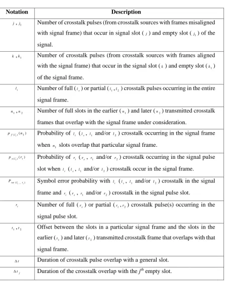
Table 1: List of Probability Parameters
Notation Description
j,j1 Number of crosstalk pulses (from crosstalk sources with frames misaligned
with signal frame) that occur in signal slot ( j) and empty slot ( j1) of the
signal.
k,k1 Number of crosstalk pulses (from crosstalk sources with frames aligned with the signal frame) that occur in the signal slot (k) and empty slot (k1)
of the signal frame.
i
l Number of full (
s
l ) or partial (l1,l2 ) crosstalk pulses occurring in the entire signal frame.
1
n ,n2 Number of full slots in the earlier (n1) and later (n2) transmitted crosstalk frames that overlap with the signal frame under consideration.
) ( 1
)
( n
p
i
l
f Probability of li (ls, l1 and/or l2) crosstalk occurring in the signal frame
when n1 slots overlap that particular signal frame.
) (
)
(l i
s r
p
i Probability of ri (rs, r1 and/or r2) crosstalk occurring in the signal pulse
slot when li (ls, l1 and/or l2) crosstalk occur in the signal frame.
) _ (li ri
we
P Symbol error probability with
i
l (ls, l1 and/or l2) crosstalk in the signal frame and ri (rs , r1 and/or r2) crosstalk in the signal pulse slot.
i
r Number of full (
s
r ) or partial (r1,r2) crosstalk pulse(s) occurring in the signal pulse slot.
1
t ,t2 Offset between the slots in a particular signal frame and the slots in the earlier (t1) and later (t2) transmitted crosstalk frame that overlaps with that
signal frame.
t
Duration of crosstalk pulse overlap with a general slot.
j
t
Duration of the crosstalk overlap with the jth empty slot.
The moment generating function (MGF) describing the random variable of the current Ysig (t)
(where sig = 0 or 1 depending on pulse transmitted or not , t is the duration of the crosstalk
a signal pulse and possibly a single XT pulse (or some fraction of one) is derived using the
same treatment as [21, 26, 27]. It is written as:
s s s s s s sig t sq XT o t XT t sq t sq o t tr t sq L t sq o t Y e RN dt t P e RG e RN dt t sigP e RG e RN s M _ ) ( 1 ) ( 1 exp 1 1 ) ( 1 exp 1 1 ) ( (1)where tts if XT slots align with signal slots otherwise t1 or t2 , and for no crosstalk in the
slot, t = 0. Also, Ptr and PXT are the DPPM rectangular pulse and the crosstalk pulse power
respectively, both defined at the photodetector input, R h , is the photodetector quantum
efficiency, h is Planck’s constant, is the optical frequency, q is the electron charge,
h NFG
No 0.5( 1) is the single polarisation ASE power spectral density (PSD) at the amplifier
output (and also at the photodetector input if demultiplexer nominal loss is neglected), G and
NF are the optical amplifier gain and noise figure respectively, L Boptmtts is the product of
spatial and temporal modes [2], Bopt is the demux channel optical noise bandwidth and mt is
the number of ASE noise polarisation states. No_XT is the ASE PSD at the photodetector at
crosstalk wavelength and RXT Ptr PXT is the signal-to-crosstalk ratio, fixed at the output of
the demux. The MGF has been modified to account for crosstalk –ASE beat noise assuming
the crosstalk and the desired signal experiences the same ASE noise at the amplifier output
[20]. The overall MGF including the zero mean Gaussian thermal noise is given as:
2 exp ) ( ) ( 2 2 ) ( ) (
t Y t th
X s s M s M sig sig (2)
where 2 th
Following [1, 2], the means and variances of the random variables representing the integration
over the slot that contains only the signal pulse, only crosstalk pulse, both signal and crosstalk
pulses and no pulses (i.e. empty slot) are derived from the overall MGF, and are respectively
generally written as:
s XT tr s o t X t t P sigP RGq t LRqN
sig( )
(3)
_ 2
2 2 2 2 2 )
( 1 2 1 2
) 1 ( s XT XT o s tr o s o o th t X t t P RN t sigP RN RGq t RN N LRq sig (4)
Given that each symbol has equal probability of being transmitted in a slot, the probability that
a symbol is successfully received in the presence of crosstalk Pws(li_ri) 1Pwe(li_ri) where
) _ (li ri
we
P is the symbol error probability in the presence of crosstalk, ri and li is,1,2 denote
the number of crosstalk (of duration ts, t1 or t2) occurring in the signal pulse slot and signal
frame respectively. Thus for single crosstalk case, ri{0,1} while li {0,1,2}. Following the
same treatment as [1], one can write that:
} ) ) ( ( slot sig 1 1 ) _ (
n j j j r lws P X t X
P
i
i (5)
where X j represents the content of the non-signal slot X0(tj)andtj is the crosstalk overlap
with the jth (empty) slot.
Assuming that the random variablesX1(t) and X0(tj) are Gaussian, the expression
)) ( ) (
(X0 t X1 t
P j using the Gaussian approximation (GA) of the ASE beat noises, is of the
) ( 2 erfc 5 . 0 )) ( ) ( ( 2 ) ( 2 ) ( ) ( ) ( 1 0 0 1 0 1 j j t X t X t X t X
j X t
t X P (6)
For the CB we have that the general form for random variable X and a fixed threshold is
X sX
P exp , s0. Thus PX M X (s)es, and manipulation of this for the
difference of two random variables implies that,
) 0 ( ) ( ) ( )) ( ) (
( 0 1 ( ) ( )
0
1
t X t M s M s s
X P j t X t X
j (7)
For the MCB [2], s th
X s e s
M X
P ( ) . Modifying this inequality for the difference of
two random variables for X0(tj) and X1(t) which both have the same thermal noise
contribution then yields,
) 0 ( 2 ) ( ) ( )) ( ) ( ( ) ( ) ( 1 0 0 1
s
s s M s M t X t X P th t X t X j j
(8)
For the FA and OSA cases the symbol error probability in the presence of a specific crosstalk
combination is written as,
s s s s s s r l s r l n r l
we P X X t P X t X t
P ( _ )1(1 ( 0(0) 1( ))) 1( )(1 ( 0( ) 1( ))) (9)
where ls and rs are the number of crosstalk of duration ts occurring in the signal frame and
signal pulse slot respectively, t ts if crosstalk hits signal pulse slot, otherwise t0.
Similarly, the symbol error probability in the presence of crosstalk for the SM case is written
as, 2 2 1 1 2 1 2
1 1 (1 ( (0) ( ))) (1 ( 0( 1) 1( ))) (1 ( 0( 2) 1( )))
1 1 0 ) , _ , ( r l r l n r r l l
we P X X t P X t X t P X t X t
P
where l1,l2 and r1,r2 are the number of crosstalk of duration t1,t2 occurring in the signal frame
and signal pulse slot respectively, l1l2 r1 r2, tt1 or t2 if crosstalk of duration t1 or
2
t respectively hits the signal pulse slot, otherwise t0. Note that in writing (10) part
crosstalk pulses are counted. So, for example, a whole crosstalk pulse in the frame will
nevertheless count as a unit contribution to both l1 and l2.
4 BER Analysis (single crosstalk)
For a single interferer, only one crosstalk pulse can hit the signal slot or an empty slot, although
more than one crosstalk pulse can impair the signal frame if there is a misalignment between
the signal and crosstalk frames. Clearly, for FA and OSA, only a full crosstalk pulse with
overlap durationt ts may occur. Let pf(ls)(n1) denote the probability of ls crosstalk pulses
hitting the signal frame where n1 is the number of whole slots in crosstalk frame 1 that overlap
the signal frame. Also let ps(l )(rs)
s denote the probability of rs out of ls crosstalk pulses hitting
the signal slot so that the probability that a full crosstalk pulse hits the signal pulse slot
n l
ps l s
s
) 1 (
)
( and the probability that full crosstalk pulse(s) hit an (unspecified) empty slot
n l n
ps l s
s
) ( ) 0 (
)
( . Furthermore, once there is slot misalignment (SM), any or both partial
crosstalk pulse(s) with overlap durations t t1 and t t2 (where ts t1 t2) could occur. Thus,
) ( 1
) , (1 2
n
pf l l denote the probability of l1 and l2crosstalk pulses hitting the signal frame and
) , ( 1 2
) , (1 2
r r
ps l l denote the probability of r1 out of l1 and r2 out of l2 crosstalk pulses hitting the
Frames Aligned (FA)
Since there is only one pulse in a frame, it may be seen in Fig. 2a that for FA only one full
crosstalk pulse can impair the signal frame and pf(1)(n)1 (seen from the special case of
2 2 1 2
1 1 ) 1
( (n ) (n (n n ) ) n
pf with n1 n in OSA below). As every frame’s pulse has equal likelihood of being in any slot, the probability that a crosstalk pulse hits the signal slot for FA
n
ps(1)(1)1 , and the probability that a crosstalk pulse hits an empty slot ps(1)(0) (n1) n.
The overall BER in the presence of crosstalk for frames (and slots) aligned is given as [28],
) )
0 ( )
1 ( ( ) 1 (
2 s(1) we(1_1) s(1) we(1_0) P p P
p n
n
BER
(11)
Only Slots Aligned (OSA)
Once there is a misalignment (whether frames only or frames and slots), it is possible for zero,
one or two crosstalk pulses to impair the signal frame. Fig 2b shows a typical example of how
two crosstalk from a single interferer can impair the signal frame, however, these two crosstalk
can only be in different slots in the signal frame as only one crosstalk can hit a slot for single
crosstalk case. If the pulse in crosstalk frame1 in Fig. 2b was transmitted much earlier in that
frame instead, there will be only one crosstalk impairing the signal frame. Furthermore, if
additionally the pulse in crosstalk frame2 in Fig. 2b was transmitted later, there will be no
crosstalk impairing the signal frame.
Using Fig. 2b, with n1n2 n, the occurrence probabilities p ( )(n1)
s
l
f for the three different
possibilities of a hit on the signal frame are found as 2
1 1 1 ) 2 ( 1 ) 0
( (n) p (n ) n (n n) n
pf f and
2 2 1 2
1 1 ) 1
( (n ) (n (n n ) ) n
pf . Also the bit error rate contributions for the different possibilities
) )
0 ( )
1 ( ( ) 1 ( 2 ) ( )
( 1 ( ) 1 ( ) ( _1) ( ) ( _0)
s s
s s
s
s f l sl we l s l we l
l p P p P
n n n p n
BER
(12)
with the no crosstalk symbol error probabilityPwe(0_0) treated the same as in [1, 2], and
0,1,2
s
l , ( _1)
s
l we
P and ( _0)
s
l we
P are calculated using (9) for rs 1 and 0 respectively as in the
FA case. However, since there could be two crosstalk in the signal frame under OSA, the
overall BER in the presence of crosstalk for only slots aligned is calculated by summing up all
the error contribution calculated from (12) for all values of ls and the conditioning on n1 is
removed through averaging (assuming signal and crosstalk walk off each other sufficiently
fast). It is written as
2
0
1 1
) ( 1
1 s
s
l l n
n
n BER n
BER (13)
Slots Misaligned (SM)
The number of different crosstalk combinations occurring in the signal frame increases with
slot misalignment, with the detailed analysis becoming complicated. Considering Fig. 2c, with
1
2
1n n
n (note the difference to the OSA case), there are seven different crosstalk
possibilities each with different occurrence probability ( , )( 1)
2
1 n
pf l l calculated from a given n1
(contributing to the overall symbol error probability) regarding how much crosstalk hits a frame
as follows:
i) No crosstalk in the signal framewith probability 2
1 1
1 ) 0 , 0
( (n ) (n 1)(n n ) n
pf : e.g.
as shown when the pulses in XT frame 5 and frame 6 respectively occur before the
ii) Only one t1 partial crosstalk pulse in the signal frame with probability
2 1 1 ) 0 , 1
( (n ) (n 1) n
pf : e.g. as shown when XT frame 2 pulse occurs at signal frame
1 end while the XT frame 1 pulse occurs before the start of signal frame 1.
iii) Only one t2 partial crosstalk pulse in the signal frame with probability
2 1 1
) 1 , 0
( (n ) (n n ) n
pf : e.g. as shown when XT frame 3 pulse occurs after signal
frame 2 ends while the XT frame 2 pulse occurs at the start of signal frame 2.
iv) One each of t1 and t2 partial crosstalk pulse in the signal frame with occurrence
probability 2
1 1
2 1
) 1 , 1
( (n ) ((n 1) 1) (2(n 1)(n n )) n
pf : e.g. as shown when XT frame
6 pulse occurs within signal frame 6. The other possibilities (not shown) are, (a)
when XT frame 7 pulse occurs within signal frame 6 and (b) where each of XT
frames 6 and 7 contribute a part pulse at the start and end of signal frame 6
respectively.
v) One t1 and two t2 partial crosstalk pulses in the signal frame with probability
) ) 1 ( ) (
(pf(1,2) n1 n1 n2 : e.g. as shown when whole XT pulse from XT frame 5
occurs within signal frame 4 and XT frame 4 pulse occurs at the start of signal frame
4.
vi) Two t1 and one t2 partial crosstalk pulses in the signal frame with probability
) ) ( ) (
(pf(2,1) n1 n n1 n2 : e.g. as shown when whole XT pulse from XT frame 3
occurs in signal frame3 and XT frame 4 pulse occurs at the end of signal frame 3.
vii) Two each of t1 and t2 partial crosstalk pulses in the signal framewith occurrence
Also, at the slot level for the SM, the probabilities that partial crosstalk pulses of duration t t1
and t t2 hit the signal slot are ps(l1,l2)(1,0)l1 n and ps(l1,l2)(0,1)l2 n respectively, and for a
hit on empty slot, ps(l,l )(0,0) (n l1 l2) n 2
1 .
Assuming the slot is discretized into m small units of length tc ts m such that the minimum
slot offset equals tc, then t1 takes values from tc, 2tc, 3tc... mtc where t1t2 ts mtc. For
definiteness, m100 is used in the calculations in this paper as higher values of m do not show
any significant effect on the results, but rather increases the computational time. The OSA case
is recovered for m 1.
The bit error rate contribution when there is no crosstalk is written as,
) 0 , 0 _ 0 , 0 ( 1 ) 0 , 0 ( 1 ) 1 ( 2 ) ( )
( f Pwe
n n n p n BER
(14)
while for the other possibilities, it is generally written as :
) ) 0 , 0 ( ) 1 , 0 ( ) 0 , 1 ( ( ) 1 ( 2 ) ( 1 ) ( ) 0 , 0 _ , ( ) , ( ) 1 , 0 _ , ( ) , ( ) 0 , 1 _ , ( ) , ( 1 ) , ( 1 , 2 1 2 1 2 1 2 1 2 1 2 1 2 1 1 2 1 l l we l l s l l we l l s l l we l l s l l f t t t l l P p P p P p n n n p m n BER s c
(15)The no crosstalk symbol error probability Pwe(0,0_0,0) is calculated the same as Pwe(0_0) in the
SA case, and l1,l20,1,2 excluding the case where (l1,l2)(0,0). The other symbol error
probabilities Pwe(l1,l2_1,0),Pwe(l1,l2_0,1), and Pwe(l1,l2_0,0) are calculated using equation (10) for
) ,
(r1 r2 (1,0), (0,1) and (0,0).
The overall BER in the presence of crosstalk for slots misaligned is calculated by summing up
all the error contributions calculated from (14) and (15) with the conditioning on n1 removed
( ) ( ) )
( )
( )
( 1
1
2
1
1 2 , 1
1 , 1
0 , 1 1
1 , 0 1
1 1
1 1
n
n l
l
l n BER n
BER n
BER n BER n BER n
BER (16)
5 Single Crosstalk Results
The system parameters used in the model are listed in Table 1. No_XT is fixed by No RXT at
the receiver with RXT 1, i.e. assuming that the crosstalk and the accompanying ASE have
been attenuated by the demultiplexer upon coupling to the desired signal photodetector. The
same data rate is assumed for both crosstalk and signal. The DPPM thermal noise variance is
back calculated using a bandwidth expansion factor such that 2 exp 2
OOK th DPPM
th B
where
M
Bexp 2M is the DPPM bandwidth expansion factor [29] and thOOK 7 x 10⁻⁷ A is obtained from a model of a pinFET receiver with Rb 2.5Gbps at BER of 1012 assuming a sensitivity
of 23dBm [19]. The demux (or OBPF) channel bandwidth is 76GHz with 100 GHz adjacent
channel spacing, this is about the same with those seen in [30, 31] and will easily accommodate
the slot rate of 45.7GHz for maximum DPPM coding level of M 7 considered [2]. Typical
values for adjacent channel rejection ratio ranges from -20 dB to -30 dB [30-32], however in
this work, the level of crosstalk (relative to signal at the photodiode) which could be worsened
by asymmetric demux input powers is allowed to vary from negligible case of -30 dB to a very
worse case of -5 dB and the resulting crosstalk effect is calculated and shown for each case. A
target BER of 9
10 is considered for systems without forward error correction coding (FEC)
[33, 34], and 3
10 is considered for systems with FEC. Also the required optical power is
defined as the average power at the input of the optical amplifier required to achieve the target
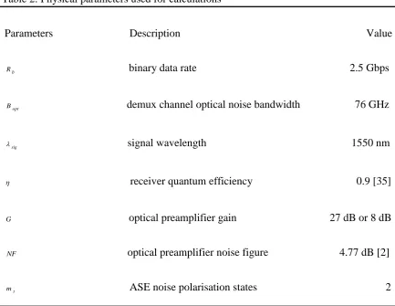
Table 2: Physical parameters used for calculations
Parameters Description Value
Rb binary data rate 2.5 Gbps
Bopt demux channel optical noise bandwidth 76 GHz
sig signal wavelength 1550 nm
receiver quantum efficiency 0.9 [35]
G optical preamplifier gain 27 dB or 8 dB
NF optical preamplifier noise figure 4.77 dB [2]
[image:18.595.85.519.118.453.2]mt ASE noise polarisation states 2
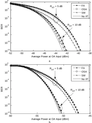
Fig. 3 shows the single crosstalk BER curves using the MCB technique for FA, OSA, SM and
no crosstalk cases with high signal to crosstalk ratio (RXT 10 dB) and moderate signal to
crosstalk ratio (RXT 5dB) at low coding level (M 1) and relatively high coding level (M 5) . The curves for the GA and CB techniques are similar, just offset by less than 0.3 dB at a BER
of 9
10 .
The BER for FA case is seen to exceed all other cases in all the methods considered and thus
results in the worst case power penalty. The OSA BER coincides with the FA BER at M 5,
while the SM case produces the best BER curves at all coding levels. The similarity between
the OSA and the FA (which also is a special and dominant subcase of the OSA, occurring at
the probabilities of the OSA crosstalk distribution. For example, at minimum overlap of frame1
in Fig. 2b, n1 1 and the OSA probabilities are dominated by the probability of one crosstalk
hitting the signal frame pf(1) (1 (n1)2) n2 (pf(0) pf(2) (n1) n2). It is easily seen that as
[image:19.595.125.436.206.621.2]n gets larger, pf(1) 1while pf(0) pf(2) 0 and OSA approximates to FA.
Fig. 3: BER against average power at OA input (dBm) using MCB, G = 27dB, for 1 crosstalk - RXT = 10 dB and 5 dB (a) M = 1 (b) M = 5
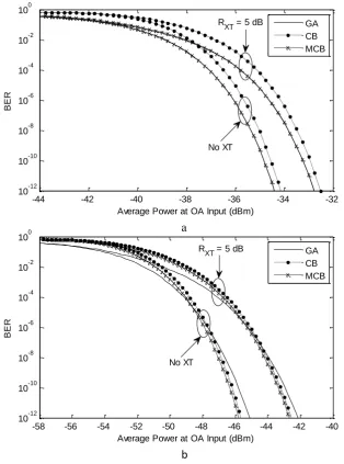
Fig. 4 shows a comparison of the GA, CB and MCB performance at low gain G 8dB and high
gain G27 dB with a single crosstalk source and M 2. The MCB coincides with the GA at
b a
-52 -50 -48 -46 -44 -42 -40 -38
10-12 10-10 10-8 10-6 10-4 10-2 100
Average Power at OA Input (dBm)
BER
FA OSA SM No XT RXT = 5 dB
RXT = 10 dB
-60 -55 -50 -45
10-12 10-10 10-8 10-6 10-4 10-2 100
Average Power at OA Input (dBm)
BER
FA OSA SM No XT RXT = 5 dB
low gain, but shifts close to the CB at high gain as the ASE noise reduces the significance of
the thermal noise. The GA on the other hand is seen to exceed the CB and MCB (which are
upper bounds) at high gain with no crosstalk and in the presence of crosstalk. The margin with
which the GA exceeds the MCB and CB widens as the coding level and the noise equivalent
bandwidth Be of the DPPM receiver increases. This inconsistent behaviour of the GA is well
reported for both OOK and DPPM systems[2, 26], but it has the advantage of being a simple
[image:20.595.124.439.277.701.2]and quick performance evaluation technique.
Fig. 4: BER against average power at OA input (dBm) using M = 2, for FA single crosstalk with RXT = 5 dB (a) G = 8 dB (b) G = 27 dB
b a
-44 -42 -40 -38 -36 -34 -32
10-12 10-10 10-8 10-6 10-4 10-2 100
Average Power at OA Input (dBm)
BER
GA CB MCB RXT = 5 dB
No XT
-58 -56 -54 -52 -50 -48 -46 -44 -42 -40
10-12 10-10 10-8 10-6 10-4 10-2 100
Average Power at OA Input (dBm)
BER
GA CB MCB R
XT = 5 dB
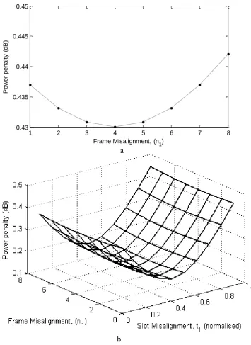
To further understand the single crosstalk system, consider Fig. 5 which shows the result of
power penalty as a function of fixed misalignment. Each point in Fig. 5a presents the power
penalty for the different fixed slot alignments (subcases) that is averaged to obtain the overall
power penalty for the OSA case The penalty at n1 8 corresponds to the penalty for FA. The
best performance for the fixed slot alignments is attained at n1 4, this is because the
probability of no crosstalk impairing the signal frame pf(0)(n1) is highest for such
misalignment. Fig. 5b presents the power penalty for fixed frame and slot misalignment SM
and gives a better insight of a more practical system. The result highlights the importance of
the averaging approach for realistic systems as recommended earlier. All the points in Fig 5b
are averaged to obtain the overall power penalty for the SM case as per (16). The points along
the n1 axis at t1 1 are the fixed slot alignment points and are the same as the result presented
in Fig. 5a. The FA point occurs at n1 8, t1 1, and is seen to present the worst penalty.
Optimum points also occur along the t1 axis at t1 0.5 and implicitly, at t2 0.5. This is
because the maximum power of either partial crosstalk i.e. max{ , }
2 1 t
t P
P is lowest at that point.
On the left of this optimum, t2 0.5 and on the right t1 0.5. Thus, it is clearly seen that the
impact of a single high power crosstalk is worse than that of many crosstalk of equivalent
power. The result in Fig. 5 could be of practical importance in a non-dispersive channel like in
free space where fixed misalignment may persist for a longer duration that averaging may not
Fig. 5: Power penalty as a function of fixed misalignment using MCB (single crosstalk) for M = 3 and RXT = 10 dB at BER = 10
-9
(a) Frame misalignment in OSA case (b) Frame and slot misalignment in SM case
The remaining results for single crosstalk analysis are obtained assuming the FA case (which
has just been shown as the worst case performance).
In Fig. 6, the result of the required signal power and the power penalty as a function of DPPM
coding level and signal to crosstalk ratio using the MCB is shown. The required signal power
a
b
1 2 3 4 5 6 7 8
0.43 0.435 0.44 0.445 0.45
Frame Misalignment, (n1)
P
o
w
e
r
p
e
n
a
lt
y
(
d
B
in Fig. 6a is seen to decrease as the coding level increases for all values of signal to crosstalk
ratio, but at each coding level, the required signal power increases as the crosstalk power
increases. The same pattern is also seen in Fig. 6b with the power penalty increasing as the
crosstalk power increases for each coding level. The ideal OOK power penalty (i.e. with
Fig. 6: DPPM coding level and Signal-to-crosstalk ratio against Required signal power and Power penalty using MCB (FA single crosstalk) (a) Required signal power (b) Power penalty
(c) DPPM compared with OOK (Power penalty vs. Signal-to-crosstalk ratio)
a
b
c
5 10 15 20
0 0.5 1 1.5 2 2.5 3
Signal to Crosstalk ratio (dB)
P
o
w
e
r
p
e
n
a
lt
y
(
d
B
)
OOK
DPPM (M = 1) DPPM (M = 2) BER = 10-9
6 BER Analysis (multiple crosstalk)
For a large number of crosstalk arising from different wavelength channels in the system, the
analysis under the constraint of slot or frame misalignment could be very complex and
computationally intensive. It could require examining the content of each slot under every
possible misalignment of slots and/or frame for all the crosstalk in order to determine their
occurrence probabilities and symbol error probability contributions. However, the assumption
of all frames aligning (FA) (acceptable as argued previously for a single crosstalk) becomes
less likely with increasing N such that imposing such constraint overestimates the BER or
power penalty for largeN values. Therefore the only slots aligned (OSA) approach seems to
be the most sensible for multiple crosstalk as it is also much quicker than the SM approach.
The multiple crosstalk analysis is considered for M 1 and M 2, which are more practical
cases for WDM systems and the analysis is facilitated by the GA for computational ease. The
probabilities for the OSA approach have been validated by Monte Carlo simulation and are
presented analytically only for M 1. For simplicity, the probability of crosstalk distribution
for M 2 is generated by Monte Carlo simulation. All the crosstalk pulses are assumed to have
equal power. This is the case when there is symmetry in the transmission link. Alternatively,
when the amounts of crosstalk in individual wavelengths are different or there is a single
dominant crosstalk in the system it may be more convenient to add all the interfering crosstalk
power together and treat the equivalent crosstalk power as if it is from a single wavelength
using the single crosstalk model discussed earlier. This at least provides an upper bound for the
Frames Aligned (FA)
Under FA and for M 1, there are only two slots in the frame and crosstalk pulses can either hit the signal slot or the empty slot. The probability that for N crosstalk signals, c of them hit
the signal slot while d N c of them hit an empty slot is defined by the binomial,
d c s c N d c p 2 1 2 1 ) , ( (17)
and the overall BER in the presence of N crosstalk pulses for M 1 is written as:
N c s ss c d P X dt X ct
p n n BER 0 1
0( ) ( )))
( 1 ( 1 ) , ( ) 1 (
2 (18)
Also, for M 2, the probability distribution of crosstalk between the signal slot and the three empty slots is a binomial while the distribution of crosstalk within the three empty slots is a
trinomial. The total probability distribution is a product of the binomial and trinomial
distributions, written as:
c N c s d d d N-c c N d d d c p 4 1 4 1 ! ! ! )! ( ) , , , ( 3 2 1 3 2
1 (19)
and the overall BER in the presence of N crosstalk pulses for M 2 is written as:
1 (1 ( ( ) ( )))(1 ( ( ) ( )))(1 ( ( ) ( )))
) , , , ( ) 1 ( 2 1 3 0 1 2 0 1 1 0 3 2 1 0 , ,
0 1 2 3
s s s s s s s d d d d N c ct X t d X P ct X t d X P ct X t d X P d d d c p n n BER
(20)where d1,d2,d3 are the number of crosstalk in empty slot 1, 2, 3 respectively, and
2 1
3 N c d d
d . X 0(dzts) andX1(cts) are the random variables for empty slot zhit by d
Only Slots Aligned (OSA)
The simplest method to generate the probability distribution of multiple crosstalk for the OSA
case is by simulation, but for completeness, the analytical method is presented for M 1.With the OSA constraint, there is a chance that all, some, or no crosstalk frames align with the signal.
For M 1, and considering N crosstalk with w frames aligned with the signal frame, the total
probability that c and d crosstalk pulses hit the signal slot and empty slot of the signal frame respectively is written as,
q w N q N s j w N j w N k w w N n w d c p 2 1 2 1 2 1 1 ) , ( (21)
where q k j j1, c k jand d k1 j1.
k and k1 are the number of crosstalk pulses from crosstalk with frames aligned with the
signal frame that hit the signal slot and empty slot in the signal frame respectively and j and
1
j are the number of crosstalk pulses from crosstalk with frames misaligned with the signal
frame that hit the signal slot and empty slot in the signal frame respectively.
The overall BER in the presence of N crosstalk pulses for M 1 is written as:
7 Multiple Crosstalk Results
Except where stated otherwise, the same parameters used for the single crosstalk model are
maintained for the multiple crosstalk model. Also, the signal to crosstalk ratio RXT as used in
the multiple crosstalk results refers to signal to single crosstalk ratio, arising as it does typically
from the demultiplexer crosstalk rejection. The OOK model follows the same model for
multiple crosstalk sources in [18] and with perfect extinction ratio assumed (so that any
advantage of DPPM is not overstated).
The result of DPPM power penalty analyses for multiple crosstalk for M 1and M 2 is compared with power penalty for OOK in Fig. 7 for target BER of 10-9. Clearly, DPPM predicts
a reasonable penalty which is less than the OOK penalty for multiple crosstalk, even at low
coding levels. The DPPM improvement in power penalty becomes better as the number of
crosstalk sources increases and as the coding level increases from M 1 to M 2 . In Fig. 7c, the FA is compared with OSA and simulation for M 1 and only simulation for M 2. Although the FA seems to overestimate the power penalty, the approximation gets better for
2
M . Also, it is computationally quicker than the other approaches and provides an upper
bound for the system. These same trends in Fig 7 are seen in Fig. 8, but with lower power
penalties predicted for 10-3. This result is particularly of interest to modern high-sensitivity
Fig. 7: Power penalty against Signal-to-crosstalk ratio for OOK and DPPM (multiple crosstalk OSA and Simulation) at BER = 10-9 (a) OOK comparison with DPPM at M = 1 (b) OOK comparison with DPPM at M = 2 (c) DPPM FA compared with OSA and/or Simulation
(50 XT Signals)
a
b
c
15 20 25 30
0 1 2 3 4 5 6
Signal to Crosstalk ratio (dB)
P
o
w
e
r
p
e
n
a
lt
y
(
d
B
)
OOK
DPPM (OSA) DPPM (Simul) 50 XT Signals
30 XT Signals
15 20 25 30
0 1 2 3 4 5 6
Signal to Crosstalk ratio (dB)
P
o
w
e
r
p
e
n
a
lt
y
(
d
B
)
OOK
DPPM (Simul)
30 XT Signals 50 XT Signals
15 20 25 30
0 1 2 3 4 5 6
Signal to Crosstalk ratio (dB)
P
o
w
e
r
p
e
n
a
lt
y
(
d
B
)
DPPM (FA) DPPM (Simul) DPPM (OSA)
Fig. 8: Power penalty against Signal-to-crosstalk ratio for OOK and DPPM (multiple crosstalk OSA and Simulation) at BER = 10-3 (a) OOK comparison with DPPM at M = 1 (b) OOK comparison with DPPM at M = 2 (c) DPPM FA compared with OSA and/or Simulation
(50 XT Signals)
a
b
c
15 20 25 30
0 0.5 1 1.5 2 2.5
Signal to Crosstalk ratio (dB)
P
o
w
e
r
p
e
n
a
lt
y
(
d
B
)
OOK
DPPM (Simul)
50 XT Signals
30 XT Signals
15 20 25 30
0 0.5 1 1.5 2 2.5
Signal to Crosstalk ratio (dB)
P
o
w
e
r
p
e
n
a
lt
y
(
d
B
)
DPPM (FA) DPPM (Simul) DPPM (OSA)
M = 2 M = 1
15 20 25 30
0 0.5 1 1.5 2 2.5
Signal to Crosstalk ratio (dB)
P
o
w
e
r
p
e
n
a
lt
y
(
d
B
)
OOK DPPM (OSA) DPPM (Simul)
8 Conclusion
Analyses of crosstalk for optically preamplified WDM DPPM systems are performed for the
first time using the GA, CB and MCB. The FA case is found to marginally present the worst
power penalty. However the accuracy penalty is justified by a significant reduction in
calculation complexity. For multiple crosstalk, the probability distribution of the crosstalk is
easily obtained using Monte Carlo simulation. However for a fixed coding level, it is possible
to analytically find the probability distribution of crosstalk in the signal frame by considering
all the different multinomial contributions from every possible combination of aligned and
misaligned crosstalk frames. The approach using the OSA assumption predicts a sensible
penalty compared to the approach with FA assumption and hence presents a better
representation of a practical system. Also, the MCB is recommended as the safest method of
evaluation as it presents a tighter upper bound than the CB and is more sensitive to the optical
amplification, though the GA is computationally quicker. The coding level with M 2is a likely option for WDM DPPM free space and wireless systems because of its sensitivity
improvement for a small bandwidth expansion over OOK, and when crosstalk is present this is
References
1. Phillips, A. J., Cryan, R. A., Senior, J. M.: 'An optically preamplified intersatellite PPM receiver employing maximum likelihood detection'. IEEE Photonics Technol. Lett., 1996,
8, (5), pp. 691-693
2. Aladeloba, A. O., Phillips, A. J., Woolfson, M. S.: 'Performance evaluation of optically preamplified digital pulse position modulation turbulent free-space optical communication systems'. IET Optoelectron., 2012, 6, (1), pp. 66-74
3. Ohtsuki, T.: 'Performance analysis of indoor infrared wireless systems using PPM CDMA'. Electronics and Commun. in Japan (Part I: Communications), 2002, 85, (1), pp. 1-10 4. Leeson, M. S.: 'Pulse position modulation for spectrum-sliced transmission'. IEEE
Photonics Technology Letters, , 2004, 16, (4), pp. 1191-1193
5. Miyazawa, T., Sasase, I.: 'BER Performance Analysis of Spectral Phase-Encoded Optical Atmospheric PPM-CDMA Communication Systems'. J. Lightw. Technol., 2007, 25, (10), pp. 2992-3000
6. Garrett, I.: 'Pulse-Position Modulation for Transmission Over Optical Fibers with Direct or Heterodyne Detection'. IEEE Trans. Commun., 1983, 31, (4), pp. 518-527
7. Phillips, A. J., Cryan, R. A., Senior, J. M.: 'Optically preamplified pulse-position modulation for fibre-optic communication systems'. IEE Proc. - Optoelectron., 1996, 143, (2), pp. 153-159
8. Bongtae, K., Byoung-Whi, K.: 'WDM-PON development and deployment as a present optical access solution'. Conf. on Optical Fiber Commun. - incudes post deadline papers, 2009, pp. 1-3
9. Ke, W., Nirmalathas, A., Lim, C., Skafidas, E.: '4 x 12.5 Gb/s WDM Optical Wireless Communication System for Indoor Applications'. J. Lightw. Technol., 2011, 29, (13), pp. 1988-1996
10. Aladeloba, A. O., Woolfson, M. S., Phillips, A. J.: 'WDM FSO Network with Turbulence-Accentuated Interchannel Crosstalk'. J. Opt. Commun. Netw., 2013, 5, (6), pp. 641-651 11. Gee-Kung, C., Chowdhury, A., Zhensheng, J., Hung-Chang, C., Ming-Fang, H., Jianjun,
Y., Ellinas, G.: 'Key Technologies of WDM-PON for Future Converged Optical Broadband Access Networks [Invited]'. IEEE/OSA J. of Optical Commun. and Networking, 2009, 1, (4), pp. C35-C50
12. Liu, X., Chandrasekhar, S., Wood, T. H., Tkach, R. W., Winzer, P. J., Burrows, E. C., Chraplyvy, A. R.: 'M-ary pulse-position modulation and frequency-shift keying with additional polarization/phase modulation for high-sensitivity optical transmission'. Opt. Express, 2011 2011/12/12, 19, (26), pp. B868-B881
13. Selmy, H., Shalaby, H. M. H., Kawasaki, Z.-I.: 'Proposal and Performance Evaluation of a Hybrid BPSK-Modified MPPM Technique for Optical Fiber Communications Systems'. J. Lightw. Technol., 2013 2013/11/15, 31, (22), pp. 3535-3545
14. Caplan, D. O., Robinson, B. S.: 'WDM Mitigation of Nonlinear Impairments in Low-Duty-Cycle M-PPM Free-Space Optical Transmitters'. Conf. Optical Fiber commun./National Fiber Optic Engineers Conf., 2008, pp. 1-3
15. Liu, L., Zhang, M., Liu, M., Zhang, X.: 'Experimental demonstration of RSOA-based WDM PON with PPM-encoded downstream signals'. Chin. Opt. Lett., 2012, 10, (7), pp. 070608
17. Yanhong, W., Min, Z., Mingtao, L., Lei, L., Ting, S., Xue, C.: '100-km Long-Reach WDM-PON Using High Power Efficient On-Off Keying Codes in Downstream'. Int. Conf. on Control Engineering and Commun. Technol., 2012, pp. 697-699
18. Monroy, I. T., Tangdiongga, E. Crosstalk in WDM communication networks. Norwell, Massachusetts, USA, : Kluwer Academic Publishers; 2002.
19. Ramaswami, R., Sivarajan, K. N., Sasaki, G. H. Optical Networks A Practical Perspective. 3rd ed. Boston: Morgan Kaufmann Publishers; 2010.
20. Ma, R., Zuo, T. J., Sujecki, S., Phillips, A. J.: 'Improved performance evaluation for DC-coupled burst mode reception in the presence of amplified spontaneous emission noise and interchannel crosstalk'. IET Optoelectron., , 2010, 4, (3), pp. 121-132
21. Al-Orainy, A. A., O'Reilly, J. J.: 'Error probability bounds and approximations for the influence of crosstalk on wavelength division multiplexed systems'. IEE Proceedings J. Optoelectronics, 1990, 137, (6), pp. 379-384
22. Ke, W., Nirmalathas, A., Lim, C., Skafidas, E.: 'Impact of Crosstalk on Indoor WDM Optical Wireless Communication Systems'. IEEE Photonics Journal, 2012, 4, (2), pp. 375-386
23. Qinglong, Y., Liying, T., Jing, M.: 'Analysis of Crosstalk in Optical Satellite Networks With Wavelength Division Multiplexing Architectures'. J. Lightw. Technol., 2010, 28, (6), pp. 931-938
24. Kedar, D., Arnon, S.: 'Backscattering-induced crosstalk in WDM optical wireless communication'. J. Lightw. Technol., 2005, 23, (6), pp. 2023-2030
25. Lee, Y., Furey, L., Alexander, S., Gallagher, W. F., Salesky, R., Inui, S. Method, system and apparatus for initiating and maintaining synchronization of a pulse position modulation (PPM) decoder with a received PPM signal. Google Patents; 2004
26. Ribeiro, L. F. B., Da Rocha, J. R. F., Pinto, J. L.: 'Performance evaluation of EDFA preamplified receivers taking into account intersymbol interference'. J. Lightw. Technol., 1995, 13, (2), pp. 225-232
27. Personick, S. D.: 'Applications for quantum amplifiers in simple digital optical communication systems'. Bell Syst. Tech. J., 1973, 52, (1), pp. 117-133
28. Phillips, A. J., Cryan, R. A., Senior, J. M.: 'An optically preamplified PPM intersatellite system described by a moment-generating function formulation'. Microwave and Optical Technol. Letters, 1995, 8, (4), pp. 200-204
29. Sibley, M. J. Optical Communications : components and systems. 2nd ed. London: Macmillian Press Ltd; 1995.
30. Maru, K., Mizumoto, T., Uetsuka, H.: 'Demonstration of Flat-Passband Multi/Demultiplexer Using Multi-Input Arrayed Waveguide Grating Combined With Cascaded Mach?Zehnder Interferometers'. J. Lightw. Technol., 2007 2007/08/01, 25, (8), pp. 2187-2197
31. Hirano, A., Miyamoto, Y., Kuwahara, S.: 'Performances of CSRZ-DPSK and RZ-DPSK in 43-Gbit/s/ch DWDM G.652 single-mode-fiber transmission'. Optical Fiber Commun. Conf., 2003, pp. 454-456
32. Yu, C. X., Neilson, D. T.: 'Diffraction-grating-based (de)multiplexer using image plane transformations'. IEEE Journal of Selected Topics in Quantum Electronics,, 2002, 8, (6), pp. 1194-1201
33. Majumdar, A. K.: 'Free-space laser communication performance in the atmospheric channel'. J. Opt. Fiber Commun. Rep., 2005, 2, pp. 345 - 396