doi:10.4236/jemaa.2010.22016 Published Online February 2010 (www.SciRP.org/journal/jemaa)
Research on the Effect of High Power Microwave
on Low Noise Amplifier and Limiter Based on the
Injection Method
Dong Chen 1, Liming Xu 1, Bisheng Zhang 1, Hongge Ma 2
1Naval Academy of Armament, Beijing, China; 2Institute of Applied Electronics, CAEP, Mianyang, China.
Email: [email protected]
Received September 21st, 2009; revised November 3rd, 2009; accepted November 9th, 2009.
ABSTRACT
The reliability of electronic device is threatened in high power microwave (HPM) environment. In accordance with the situation that the emulation is ineffective in evaluating the accuracy and precision of the HPM effect to electronic de-vice, the experimental method is used to resolve the problem. Low Noise Amplifier (LNA) and Limiter are selected as the objects for the experiments, the structural characteristic of the front-end of radar receiver is described, the phe-nomena and criterion are elaborated and analyzed using injection method due to its ability to get an accurate threshold avoiding the complex coupling, the basic principle of injection experiment is demonstrated, and the method and process of effect experiment about Low Noise Amplifier and Limiter are also explained. The experimental system is established, and the system is composed of low power microwave source such as TWT, test equipment for obtaining the effect pa-rameters, and some of auxiliary equipments as camera, optical microscope or electron microscopy, attenuator, detector, and directional coupler etc. The microwave delivered from source is adjusted to the power infused by attenuator, and pour in the decanting point of effecter via directional coupler, then the couple signal created by directional coupler is input to the recording instrument after detecting by detector, finally the power of effecter is obtained. The value of power, which damages the effecter in the microwave pulse environment, is classified at the index of sensitivity, and the threshold is obtained by power diagnose and wave test. Some regular understandings of the HPM effect to electronic device are obtained based on the results of the experiments. It turns out that the index of electronic device is influenced significantly by the energy via front door coupling, the MOSFET made up of GaAs is the most wearing part to HPM in LNA, the damage threshold of LNA is about 40dBm under single pulse while in repetitive pulse the value is from 33.3dBm to 43.9dBm according to different wave band. The damage threshold of Limiter is about 56dBm to80dBm.
Keywords: High Power Microwave, Low Noise Amplifier, Front Door Coupling, Injection Experiment
1. Introduction
Nowadays electronic equipments are facing the prolifer-ating threats from HMP, thus require the equipments which have outstanding performance and complex struc-ture should have much higher reliability. The high gain aerial is widespread used in modern radar and satellite communication system, in this case the electromagnetic energy coupled in front-door is much higher than coupled in back-door, so the front-end of radar receiver and satel-lite communication system is the most vulnerable part under the threat of HPM.
The limitation of emulation in analyzing and evaluat-ing the HPM effect to electronic device caused by the complex structure of electronic equipment and incom-plete description of damage mechanism of HMP lead to
weakness on analysis[1,2]. The effect experiment is in a sense the most intuitive and efficient method to analyze the effect of electromagnetic on electronics, the threshold of sensitive components is determined by microwave effect experiment, and the result is the necessary data for analyzing the electromagnetic performance of system and hardening electromagnetic pulse. It is very important to carry out the experimental study of effect of electromag-netic on electronic devices and components for hardening the electronic system especially for military use.
2. Methodology
2.1 The Principle of Injection Experiment
and element circuit. The effect quantification of compo-nents is obtained by using this method. The microwave shall act on the effecter through the front door, and then an accurate threshold is gotten due to neglecting the complex coupling, thus applied in analyzing mechanism, principle and predicting the effect of front door coupling. The simulation research on effect mechanism is contrib-ute to understand the whole system effect, but it's not the efficient way to acquire the threshold for judging the en-tire system use, therefore, by applying the injection ex-periment method, the results about the effect on the cer-tain waveform in each interface under cercer-tain conditions will be analyzed.
The fundamental condition of injection method is low power microwave source with adjustable parameters such as TWT, parameter test equipment, some of auxiliary equipments as camera, optical microscope or electron microscopy etc. Figure 1 shows the functional block dia-gram of injection experiment [3].
The power microwave source and output terminal of signal should be separated and shielded in order to avoid the influence from reflected signal, and special attention should be paid while coaxial line transfers to the micro-wave in order not to cause the distortion of radiation and waveform, and the separation point also requires separa-tion protecsepara-tion. The test system is composed of several parts given below: power microwave source, the control parts of the source, regulation parts of the power, trans-mission and diagnosis parts of power, test equipment and recording instrument.
2.2 Design of Injection Experiment about LNA
The functional block diagram of injection experiment about LNA is shown in Figure 2. The attenuator and de-tector are both measured, The microwave delivered from source is adjusted to the power infused by attenuator, and
Microwave Power Source Power Adjustment Synchronous System Directional Coupler
Attenuator Attenuator
Detector Detector
[image:2.595.306.540.91.202.2]Recording Instrument Effecter Isolated Network Signal Source Injection Converter
Figure 1. the functional block diagram of injection experiment
[image:2.595.306.537.255.366.2]Microwave Power Source Attenuator Load Load Circulator Reflection Port Incidence Port Detector Detector Bias Supply LNA Detector Oscilloscope
Figure 2. The functional block diagram of injection experi-ment about LNA
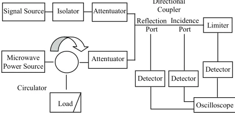
Incidence Port Signal Source Microwave Power Source Isolator Attentuator Attentuator Limiter Detector Load Circulator Directional Coupler Reflection Port Detector Detector Oscilloscope
Figure 3. The functional block diagram of injection experi-ment about Limiter
pour in the decanting point of effecter via directional coupler, then the couple signal created by directional coupler is input to the recording instrument after detect-ing by detector, finally the power of effecter is obtained. The value of power, which damages the effecter in the microwave pulse environment, is classified at the index of sensitivity, and the threshold is obtained by power diagnose and wave test[4].
2.3 Design of Injection Experiment about Limiter
The leakage of rising edge will be revealed under the action of HPM, in other words HPM can transit the Lim-iter, the power leakage may lead the next level of circuit to interference and damage, meanwhile HPM may also cause the functional decline of Limiter under certain cir-cumstance, the functional block diagram of injection ex-periment about Limiter is shown in Figure 3.
3. Analysis
3.1 Analysis of the Structural Characteristic of the Front-End of Radar Receiver
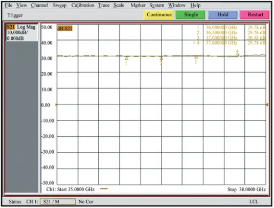
[image:2.595.56.287.518.701.2]Figure 5 and Figure 6 shows the gain of LNA before and after injection experiment, the value of gain is pro-vided by network analyzer.
front-end of radar. Figure 4 shows the composition and structure of the front-end of radar, it consists of RF, re-ceiver protector, LNA, mixer and LO [5].
The output signal can not meet the requirement of next level of circuit while the gain of LNA decline 3dB, gen-erally speaking, the value 3dB is regarded of the standard for judging whether LNA is normal or abnormal, the
3.2 Analysis of the Effect of LNA in Injection Experiment
The LNA is the vulnerable component of front-end of radar, designed by multiple cascaded straight amplifica-tion style, the noise caused by the first level of amplifier has the greatest and the most serious damage to LNA, the gain of whole amplifier is reduced while the noise tem-perature is increased once the LNA is damaged, thus bring about the SNR of the system a reduction, and fi-nally makes radar system doesn't work [3,4].
Receive protector LNA Mixer
LO
[image:3.595.310.535.179.229.2]RF IF
[image:3.595.164.432.265.468.2]Figure 4. Front end of radar receiver
Figure 5. The gain of LNA before experiment
[image:3.595.164.434.497.703.2]gain declination in injection experiment is more than 3dB after HPM is poured in, it is reputed that HPM can damage LNA efficiently.
3.3 Analysis of the Effect of Limiter in Injection Experiment
The basic function of Limiter is to control the signal un-der secure level all the time, to avoid the damage of LGA and Mixer receiving distortion of electronic equipments induced by high power signal.
The criterion for judging whether Limiter is normal or abnormal is one more than it of LNA, the first one is short circuit due to breakdown while insertion loss
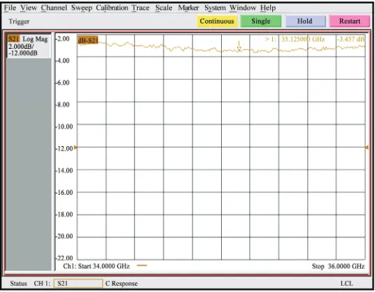
in-creased, of which 3dB is considered to be as symbol that the limiter is damaged, while an other one is the output level rises as input level rises when the value of insertion loss is constant, clipping is malfunction, the output level is twice higher than HPM is not poured in, in this case open circuit occurred in Limiter due to burn down. Figure 7 and Figure 8 shows the change of insertion loss among injection experiment, the value of insertion loss is measured by network analyzer.
[image:4.595.164.432.248.457.2]The insertion loss is higher about 10dB while HPM is poured in, it is more than the criterion (3dB), meanwhile the output level rises as input level rises, and it is obvi-ous that HPM damaged Limiter.
[image:4.595.163.432.487.703.2]Figure 7. The insertion loss of Limiter before experiment
4. Result
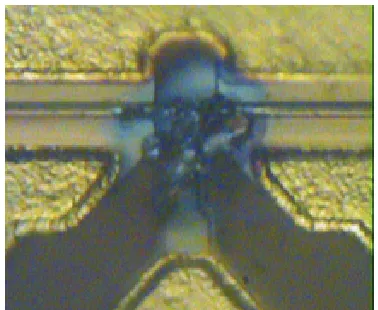
The micrograph describes the damage of LNA in injec-tion experiment is shown in Figure 9.
The result turns out that the damage of LNA is caused by damage of GaAs FET, the microwave signal should pour in the point between grid and source of GaAs FET, electric field breakdown disrupts the deletion layer and creates instantaneous current[6], on the other hand, the HPM destroy the depletion layer and grid directly, the principle of damage of LNA caused by HPM based on the results of experiment is presented below [3,4]:
1) Damage threshold of LNA for different band The LNA may be damaged while power infused is about 33.3dBm to 48.6dBm (that is 2.14W to 72.44W), the effect is arisen from the damage of GaAs FET.
The damage threshold of LNA at X band is divided into two parts: in the case of single microwave pulse the threshold is about 39.5dBm to 48.6dBm (that is 8.91W to 72.44W), while in the case of repetitive frequency mi-crowave pulse the threshold is about 39dBm to 43.9dBm (that is 7.94W to 24.55W).
2) Difference of damage threshold vs band style The difference of the damage threshold of LNA among different band is 1.6 dB to 3.5dB.
Differences of threshold may also exist at the same band. The experiment results shown that difference of LNA at the same band is 2.2dB to 9.6dB.
3) Difference of damage threshold vs pulse width Differences of threshold may also exist in different pulse width, it is 2.2dB to3.7dB.
At the same single microwave pulse, the difference of the damage threshold of LNA between single pulse and re-petitive pulse (<=100hz) is 3.7~6.5dB; the damage threshold of LNA is 39.5dBm~48.6dBm(8.91W~72.44 W)for single pulse and 33.3dBm~43.9dBm (2.14W~ 24.55W) in repetitive pulse.
[image:5.595.78.267.544.699.2]4) Difference of damage threshold vs brand of GaAs FET
Figure 9. Micrograph of LNA damaged
The damage threshold of low noise amplifier will be different when using GaAs FET of different brands.
With different models of the same brand of GaAs FET, the difference of the damage threshold would be 0.3dBm~3.1dBm.
Three types of Limiter are selected to analyze the HPM effect, the principle of damage of Limiter caused by HPM based on the results of experiment is presented be-low:
Whether to breakdown or burn down the Limiter at single narrowband microwave pulse high power should be required.
The insertion loss increased rapidly while stand-ing-wave changed very little.
The interference effect will be different when the time for the meeting of injected signal and working signal is different, which is caused by the difference of sensitivity of working signals when they work on different positions.
The damage threshold of Limiter will be different even produced by the same manufacturer, and it varies greatly when using Limiter of different brands.
5. Conclusions
The effects of HPM on electronic equipments should not be ignored, the results based on injection experiment turns out that LNA may be damaged mainly caused by the failure of GaAs FET; the damage threshold of LNA at C band is lower than it at X band, and it is much lower than Limiter.
REFERENCES
[1] M. G. Bäckström and K. G. Lövstrand, “Susceptibility of electronic systems to High-Power Microwaves: summary of test experience,” IEEE Transactions on Electromagnetic Compatibility, Vol. 46, No. 3, pp. 396–403, August 2004. [2] F. Sabath, M. Bäckström, B. Nordström, D. Sérafin, A.
Kaiser, B. A. Kerr, and D. Nitsch, “Overview of four European high-power microwave narrow-band test facili-ties,” IEEE Transactions on Electromagnetic Compatibil-ity, Vol. 46, No. 3, pp. 329–334, August 2004.
[3] Y. wang, H. G. Ma, and X. J. Cao, et al., “Proceedings of Annual Report of China Academy of Engineering Phys-ics,” Annual Report of China Academy of Engineering Physics, 2003.
[4] Y. Wang and H. G. Ma, et al, “Annual Report of China Academy of Engineering Physics,” Annual Report of China Academy of Engineering Physics, 2005.
[5] M. Skolnik, “Introduction to Radar Systems,” Third Edi-tion. McGrawHill : New York, 2001.