STREAMER
PREFACE
This instruction manual is designed to assist the new customer or potential new customer in the areas of application, installation, ope rat ion, and rna i nte na nce. Th e empha sis is on prod uct perfo rm ance from an operator's vi ewpoi nt. The ne~" Streamer operator shoul dread the entire manual over once and then return to Section 3, Operation. The operat i on sect i on refers the reader to other areas in the manua 1 for background information, as required.
TABLE OF CONTENTS SECTION 1. 2. 3. DESCRIPTION •••••••••••••••••••••••••••••••••••••••••••••••••••••••• 1.1 1.2 1.2.1 1.2.2 1.2.3 1.2.4 1.3 Introduction •••••••••••••••••••••••••••••••••••••••••••••••• General Description ••••••••••••••••••••••••••••••••••••••••• Cartridge Drive ••••••••••••••••••••••••••••••••••••••••••••• Tape Cartridge •••••••••••••••••••••••••••••••••••••••••••••• Data Transmission ••••••••••••••••••••••••••••••••••••••••••• Data Reliability, Interchangeability •••••••••••••••••••••••• Specification Summary •••••••••••••••••••••••••••••••••••••••
INSTALLATION ••••••••••••••••••••••••••••••••••••••••••••••••••••••• 2.1 2.2 2.3 2.3.1 2.4 2.4.1 2.5 2.6 2.7 2.8
Mount i ng ••••••••••••••••••••••••••••••••••••••••••••••••••••
Input Power Connection •••••••••••••••••••••••••••••••••••••• Power Supply Requirements ••••••••••••••••••••••••••••••••••• Power Transients •••••••••••••••••••••••••••••••••••••••••••• Signal Connections •••••••••••••••••••••••••••••••••••••••••• Input/Output Signal Connector ••••••••••••••••••••••••••••••• Signal Line Termination ••••••••••••••••••••••••••••••••••••• Multiple Drive Applications ••••••••••••••••••••••••••••••••• Cartridge Loading, Unloading •••••••••••••••••••••••••••••••• Temperature, Cooling ••••••••••••••••••••••••••••••••••••••••
OPERATION ••••••••••••••••••••••••••••••••••••••••••••••••••••••••••• 3.1
3.1.1
General Operation Concepts ••••••••••••••••••••••••••••
SECTION 3.1.2 3.1.3 3.1.4 3.1.5 3.1.6 3.1.7 3.2 3.2.1 3.2.2 3.2.3 3.2.4 3.2.5 3.2.6 3.2.7 3.2.8 3.2.9 3.2.10 3.2.11 3.2.12 3.2.13 3.2.14
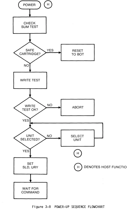
Streaming Concept-Write Mode •••••••••••••••••••••••••••••••• Streaming Concept-Read Mode ••••••••••••••••••••••••••••••••• Data Overflow and Underflow ••••••••••••••••••••••••••••••••• Host Adapter Hardware ••••••••••••••••••••••••••••••••••••••• Software Driver ••••••••••••••••••••••••••••••••••••••••••••• Disk Backup Considerations •••••••••••••••••••••••••••••••••• Operation Details ••••••••••••••••••••••••••••••••••••••••••• Input/Output Signal Descriptions •••••••••••••••••••••••••••• Data Signal Parameters •••••••••••••••••••••••••••••••••••••• Signal Line Termination ••••••••••••••••••••••••••••••••••••• Write Operation ••••••••••••••••••••••••••••••••••••••••••••• Read Operation •••••••••••••••••••••••••••••••••••••••••••••• Tape Mark ••••••••••••••••••••••••••••••••••••••••••••••••••• Append Operation •••••••••••••••••••••••••••••••••••••••••••• Repositioning •••••••••••••.••••••••••••••••••••••••••••••••• Power-Up Command Sequence, Flowchart •••••••••••••••••••••••• Write Command Sequence, Flowchart ••••••••••••••••••••••••••• Read Command Sequence, Flowchart •••••••••••••••••••••••••••• Tape Mark Command Sequence •••••••••••••••••••••••••••••••••• Reset Command Sequence •••••••••••••••••••••••••••••••••••••• Interface Timing Diagrams •••••••••••••••••••••••••••••••••••
4. THEORY OF OPERATION •••••••••••••••••••••••••••••••••••••••••••••••••
4.1 4.2 4.3
General Concept •••••••••••••••••••••••••••••••••••••••••••••• Data Handling •••••••••••••••••••••••••••••••••••••••••••••••• Tape Position Control ••••••••••••••••••••••••••••••••••••••••
SECTION 4.4 4.5 4.6 4.6.1 4.6.2 4.7 4.7.1 4.8 4.9
Tape Data Record Format ••••••••••••••••••••••
Recording Code ••••••••••••••••••••••••••••••••••••••••••••••• Error Recovery ••••••••••
Write Error Recovery ••••
Read Error Recovery •••••••••••••••••••••••••••••••••••••••••• Cartridge Tape Data Format ••••••••••••••••••••••••••••••••••• Physical Dimensions •••••••••••••••••••••••••••••••••••••••••• Head Configuration ••••••••••••••••••••••••••••••••••••••••••• Repositioning ••••••••••••••••••••••••••••••••••••••••••••••••
5. MAl NTENANCE •••••••••••••••••••••••••••••••••••••••••••••••••••••••••
6. 5.1 5.2 5.2.1 5.2.2 5.2.3 5.2.4 5.3 5.4 5.4.1 5.4.2 5.4.3
Genera 1 ••••••••••••••••••••••••••••••••••••••••••••••••••••••
Periodic Maintenance ••••••••••••••••••••••••••••••••••••••••• Magnetic Head Cleaning ••••••••••••••••••••••••••••••••••••••• Tape Cleaner Cleaning •••••••••••••••••••••••••••••••••••••••• Motor Capstan Cleaning ••••••••••••••••••••••••••••••••••••••• Heat Sink, Circuit Board and Sensor Hole Cleaning •••••••••••• Drive Disassembly •••••••••••••••••••••••••••••••••••••••••••• Troubleshooting •••••••••••••••••••••••••••••••••••••••••••••• Symptom Revi ew •••••••••••••••••••••••••••••••••••••••••••••••
Summary ••••••••••••••••••••••••••••••••••••••••••••••••••••••
Troubleshooting Flowcharts •••••••••••••••••••••••••••••••••••
PART S •••••••••••••••••••••••••••••••••••••••••••••••••••••••••••••••
6.1 6.2 6.3
General.
...
DEI Manufactured Subassemblies ••••••••••••••••••••••••••••••• Special Component Parts List •••••••••••••••••••••••••••••••••FIGURE 1-1 1-2 2-1 2-2 2-3 2-4 2-5 3-1 3-2 3-3 3-4 3-5 3-6 3-7 3-8 3-9 3-10 3-11 3-12 3-13 3-14 3-15 3-16
LIST OF ILLUSTRATIONS
Cartridge Tape Drive ••••••••••••••••••••••••••••••••••••••••• Tape Cartridge ••••••••••••••••••••••••••••••••••••••••••••••• Drive Dimensions ••••••••••••••••••••••••••••••••••••••••••••• U n i v e r sal F r a me. • • • • • • • • • • • • • • • • • • • • • • • • • • • • • • • • • • • • • • • • • • • • • Power Connector Board Detail ••••••••••••••••••••••••••••••••• Input/Output Connector Board Detail •••••••••••••••••••••••••• Host, Drive Interconnection •••••••••••••••••••••••••••••••••• Drive/Host Interface ••••••••••••••••••••••••••••••••••••••••• Cartridge File Protection •••••••••••••••••••••••••••••••••••• Write Data Flow •••••••••••••••••••••••••••••••••••••••••••••• Read Data Flow ••••••••••••••••••••••••••••••••••••••••••••••• Backup Time vs Tape Speed, Record Length ••••••••••••••••••••• Append Flowchart ••••••••••••••••••••••••••••••••••••••••••••• Repositioning Cycle •••••••••••••••••••••••••••••••••••••••••• Power-Up Sequence Flowchart •••••••••••••••••••••••••••••••••• Write Operation Flowchart •••••••••••••••••••••••••••••••••••• Read Operation Flowchart ••••••••••••••••••••••••••••••••••••• Tape Mark Management ••••••••••••••••••••••••••••••••••••••••• Reset Operation Flowchart •••••••••••••••••••••••••••••••••••• Power-Up Command, Status Timing •••••••••••••••••••••••••••••• Initial Write Timing ••••••••••••••••••••••••••••••••••••••••• Write Handshake Timing ••••••••••••••••••••••••••••••••••••••• Initial Read Timing ••••••••••••••••••••••••••••••••••••••••••
FIGURE PAGE 3-17 Read Handshake Timing ••••••••••••••••••••••••.•••••••.•••••.• 52 3-18 Write Mark Timing •••••••••••••••••••••••••••••••••••••••••••• 53 4-1 Streaming Block Diagram •••••••••••••••••••••••••••••••••••••• 55 4-2 Data Format... 56 4-3 GCR Code... 57
4-4 4-5 4-6 4-7 4-8 5-1 5-2 5-3 5-4
Write Mode Error Rewrites ••••••••••••••••••••••••••••••••••••
Track Formats ••••••••••••••••••••••••••••••••••••••••••••••••
Cartridge Tape Physical Dimensions ••••••••••••••••••••••••••• Head Configuration ••••••••••••••••••••••••••••••••••••••••••• Repositioning Cycle •••••••••••••••••••••••••••••••••••••••••• Parts Location ••••••••••••••••••••••••••••••••••••••••••••••• P.C. Board Removal ••••••••••••••••••••••••••••••••••••••••••• Head, Motor Assembly Removal ••••••••••••••••••••••••••••••••• Motor Assembly Removal •••••••••••••••••••••••••••••••••••••••
58 59 60 61 62 64 65 66 66 5-5 Troubleshooting Flowcharts •••••••••••••••••••••• 69,70,71,72,73,74
TABLE 1-1
LIST OF TABLES
Specification Summary ••••••••••••••••••••••••••••••••••••••••• PAGE
6
SECTION 1 DESCRIPTION
1.1 INTRODUCTION
The Streamer is configured as a high level, byte parallel, FIFO memory; there is no restriction on block size. The system's integrator need not be concerned with the art and physics of magnetic tape recording. All algorithms for the recording of data, the restoration of data, and the recovery from errors are contained within the Streamer. Data is sent to and from the Streamer with a si mple asynchronous handshake. Capacity and tape speed of the Streamer models are specified in the following table:
CAPACITY TAPE SPEED
(megabytes) (inches per second) MODEL
10 Mbytes 30 ips 7130
10 Mbytes 90 ips 7190
20 Mbytes 30 ips 7230
20 Mbytes 90 ips 7290
1.2 GENERAL DESCRIPTION
The Streamer is a reliable tape drive, designed to provide economical data back-up and program load functions for systems using Winchester disk drives. Streaming uses a continuous recording process offering several advantages over the conventional stop/start recording method as follows:
o eliminates need for start/stop servo electronics, thus reducing power requirements and heat dissipation. o increases tape speed and data transfer rates.
o eliminates large interblock gaps, thus increasing data volume that can be stored on tape.
1.2.1 Cartridge Drive
The Streamer is designed to write and read streaming data onto cartridges built to ANSI Standard X3.55-1977 specifications. Two tracks are used in the 10 Mbyte models while the 20 Mbyte models use four tracks. In both versions, the even numbered tracks are recorded in the forward direction; odd numbered tracks in the reverse direction. Data formats are compatible (that is, either a 10 or 20 Mbyte drive can recover data recorded on the other, however, only the first two tracks of the 20 Mbyte unit can be recovered by a 10 Mbyte drive).
The St reamer encodes data before recordi ng and decodes before transmi ssi on to the host. All overhead characters are added to the data within the drive and removed before outputting.
A universal mounting frame provides primary support for the components of the cartridge drive which consists of three major subassemblies:
o motor/heat sink assembly
o mechanical/head, flexcircuit assembly o PC board assembly
The PC board provides edge connectors for I/O signals and power. Figure 1-1 illustrates the location of major components and subassemblies within the mainframe.
Figure 1-1 CARTRIDGE TAPE DRIVE
1.2.2 Tape Cartridge
[image:11.611.107.550.48.498.2]BELT GUIDE ROLLERS (2)
TAPE SHOWN IN BOT POS IT I ON
READ/WRITE HEAD
BELT DRIVE PULLEY RUBBER COVERED DRIVE ROLLER
DRIVE MOTOR
FLAT DRIVE BELT TAKE-UP HUB
FIXED TAPE GUIDES (2) LIGHT SENSING DIRECTION OF FORWARD TAPE MOTION
Figure 1-2 TAPE CARTRIDGE
1.2.3 Data Transmission
To sustain streaming operation, the host must be capable of supplying data rates equal to or greater than:
o 128 kbytes per second (7.8 ~s per byte) for 90 ips models o 43 kbytes per second (23 ~s per byte) for 30 ips models
[image:12.615.50.429.79.479.2]1.2.4 Data Reliability, Interchangeability
Incorrect or marginal data is rewritten without stopping the streaming operation. The Streamer achieves this by first mechanically cleaning the tape with a sapphire tape cleaner. Then, to assure data integrity, written data is immediately read. Three (3) write thresholds are available for the controller during the read-after-write process. The written data is verified, byte-by-byte, with the input data. During the write process, a one's intensive GCR code is used. This creates a data bandwidth separated from the drive flutter components. This code is not sensitive to bit patterns and therefore provides greatest data recovery potent i a 1 from med i a dropouts. The hard error rate is less than or equal to one (1) in 1010.
Data written previously and now being read could be affected during media storage. However, the Streamer incorporates a CRCC technique and use of an error algorithm to solve this problem. The algorithm incorporates tape cleaning, retensioning, and threshold adjustment, as required.
The Streamer's mechanical design secures the cartridge to a rigid cast reference plane. This approach assures that data written by one drive can successfully be read on another.
The magnetic head is secured to a rigid cast frame. For the 20 Mbyte model, the head is moved and held against two precise surfaces in Jo Block configuration. This simple classic design holds the head position within 0.0005 inches.
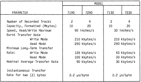
1.3 SPECIFICATION SUMMARY
Four (4) models of DEI Streamer Cartridge Tape Drives are available. Table 1-1, Specification Summary, describes parameters relative to particular model numbers.
MODEL
PARAMETER 7190 7290 7130 7230
Number of Recorded Tracks 2 4 2 4
Capacity, Formatted (Mbytes) 10 20 10 20
Speed, Read/Write Maximum 90 inches/s 30 inches/s Burst Transfer Rate
Write Mode 210 kbytes/s 210 kbytes/s
Read IVlode 290 kbytes/s 290 kbytes/s Minimum Long-Term Transfer
Rate: Write Mode 128 kbytes/s 43 kbytes/s
Read Mode 100 kbytes/s 30 kbytes/s
Nomi na 1 Average Transfer Rate 90 kbytes/s 30 kbytes/s Instantaneous Transfer
Rate for two (2) bytes 2.2 us/byte 2.2 ~s/byte
Table 1-1 SPECIFICATION SUMMARY
The Streamer will typically consume data at the Nominal Average Transfer Rate. However, to guarantee a streaming situation, the host must be capable of the Minimum Long-term Transfer Rate.
[image:14.612.51.525.195.470.2]Performance specifications common to all Streamer drive models follow:
Recording Form ••••••••••••••••••••••• Serpentine Recording Code ••••••••••••••••••••••• GCR
Head Format •••••••••••••••••••••••••• Read-While-Write with erase Recording Density •••••••••••••••••••• 7600 bits/inch (Host Data) Reliability (data):
Soft Error Rate •••••••••••••••••••
<
1 Error in 108 bitsHard Error Rate •••••••••••••••••••
<
1 Error in 1010 bits Servo Voltage ••••••••••••••••••••• 24 VDC ± 15%Other Voltage ••••••••••••••••••••• 4.85 to 5.25 VDC Dissipation:
Typi ca 1 • • • • • • • • • • • • • • • • • • • • • • • • • •• 50 watts Maximum ••••••••••••••••••••••••••• 90 watts
Width x Height x Depth ••••••••••••••• 8.55 X 4.62 x 14.25 inches Weight ••••••••••••••••••••••••••••••• 5 pounds
Mounting •••••••••••••••••••••••••••• 8 inch Standard Diskette Operating Temperature •••••••••••••••• +50 to +450 C
Storage Temperature •••••••••••••••••• -300 to +600 C
Relative Humidity •••••••••••••••••••• 20 to 80% RH
Altitude ••••••••••••••••••••••••••••• -200 to 15,000 feet Vibration Limits •••••••••••••••••••• O.lg, 3-300 Hz
Shock Limit ••••••••••••••••••••••••.• 3 gis, 20 ms impulse on Z-axis Mean Time Between Failures* ••••••••••
>
3500 hours* Excludes head and motor life
SECTION 2 INSTALLATION
2.1 MOUNTING
The Streamer's universal standard 8-inch frame permits side or bottom mounting of the drive. It can be mounted in most any orientation without affecting its performance; however, the following two operating positions are not recommended:
o the drive mounted such that the oxide surface of the tape is below the tape cleaner (tape material removed by the cleaner can fall back onto the tape surface resulting in loss of data)
o the drive mounted where the cartridge is inserted with the base plate up
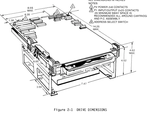
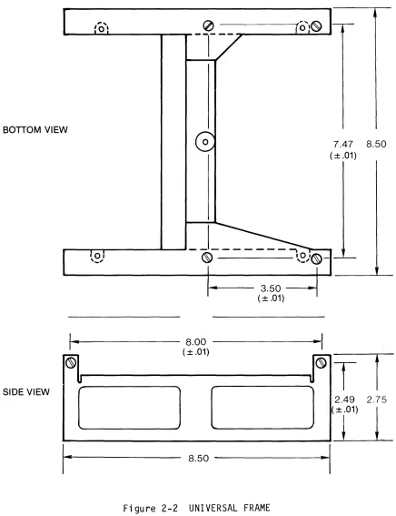
Overall drive dimensions, including the universal mounting frame, are shown in Figure 2-1. Mounting holes are compatible with 8/32 inch bolts. See Figure 2-2, Universal Frame, for additional mounting information.
ALL DIMENSIONS IN INCHES NOTES:
&
P2 POWER 2x6 CONTACTS~ P1 INPUT/OUTPUT 2x25 CONTACTS .05 MINIMUM SWAY SPACE IS
RECOMMENDED ALL AROUND CARTRIDGE AND P.C. ASSEMBLY
&
ADDRESS SELECT SWITCH [image:16.612.46.515.375.740.2]BOTTOM VIEW
SIDE VIEW
,. ...
!o!
a . - - - 3.50 -~ (± .01)
t - I . . . - - - 8.00 ---~
(± .01)
7.47 8.50
(± .01)
1 [
2.49 2.75
~_
~
__
==-~---Ill
8.50
---i·~1
[image:17.612.98.534.119.686.2]2.2 INPUT POWER CONNECTION
Power is supplied to the Streamer through the card-edge connector (P2) on the PC board (see Figure 2-3 for location). Power connector board details are shown in Figure 2-3. The mating connector is a 12-pin edge-type connector, Winchester PIN BBDJ6-S005G (or equivalent) with AWG #20 conductor wi res. If the key (between pi ns 4 and 5) is not used, the mating connector can be installed in either position.
r---.,
r
POWER CONNECTOR LOCATION14.09 TOP VI EW
PC BOARD
POWER CONNECTOR
P2
•
3.96 REAR VIEW
I
_t_"---__
__+_~~
r-
1.38KEY\...
~
III
n
1ft .
301r-2 PLC' 5
I
j1 2 3~51~
TOPSIDE FINGERSREVERSE SIDE FINGERS
_I-I
.
I
.156(
typ).100 ~
I
NON-CUMULATIVE~ ~ .062 (typ)
____ 1 .083
---J
[image:18.612.104.492.262.627.2]2.3 POWER SUPPLY REQUIREMENTS
The voltages and currents required to operate the Streamer are shown in Table 2-1 along with the applicable pin numbers of the P2 power connector.
PIN PIN VOLTAGE (VDC) CURRENT (AMPS) COMMENTS AND NUMBER NAME MIN MAX MIN TYP MAX REFERENCE NOTES
4,C V5+ 4.85 5.25 2.8 3.0 3.6 +5 VDC, Ripple
i
2% inclusive of toler-ances (see notes 3 and 4)1,2,B LCOM Logic Common, logic
current return (see note 1)
3,0 V24+ 20.4 27.6 0.2 1.0 2.6 +24VOC (see notes 2, 3 and 4)
5,E,F SCOM Servo Common, servo
current retu rn (see note 1)
A,6 CCOM Chassis Common, drive
return to power supply (see note 1 )
NOTES: 1. MUST BE TIED TOGETHER AND TO GROUND AT ONE POINT IN POWER SUPPLY.
2. Maximum current requirements are for period
i
300 ms A defective cartridge can extend the maximum current periods3. All voltages measured at drive power connector with drive in operation
Table 2-1 STREAMER POWER SUPPLY REQUIREMENTS
2.3.1 Power Transients
Power transients must not exceed the limits specified for the power requirements in Table 2-1. To avoid spurious input commands during power-on or power-off sequenci ng, the host mu st provi de a fa i 1-safe method of maintaining the drive in a non-operative state. Power to the drive should not be turned on or off with a cartridge installed in the useable recording area. Failure to observe this precaution may destroy previously recorded data. If the drive shares a common power supply with a disk, the system designer must be aware that large disk current
2.4 SIGNAL CONNECTIONS
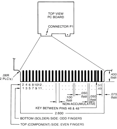
2.4.1 Input/Output Signal Connector
Input/output signals interface with the Streamer through the edge connector (PI) on the PC board. Connector pi n 1 ocat ions are shown in Fi gure 2-4. Maxi mum cabl e 1 ength from the connector is 25 feet (8 meters). The mating connector is a 50-pin edge-type 3M PIN 3415-001 or equivalent.
.06R
TOP VIEW PC BOARD
(2 PLC's)
.--~ 2 4 6 8 1 01 2. .
1357911 . .
. 'J'L'" .
. . . . . . .49'~50
.050
.100 (typ) .050
(typ) (typ)
NON-ACCUMULATIVE
KEY BETWEEN PINS 46 & 4 8 - - - '
~--- 2.600 - - - '
BOTTOM (SOLDER) SIDE: ODD FINGERS
~-TOP (COMPONENT) SIDE: EVEN FINGERS
Figure 2-4 INPUT/OUTPUT CONNECTOR BOARD DETAIL
--- .075
[image:20.612.94.499.213.661.2]2.5 SIGNAL LINE TERMINATION
Input, output and data signal lines should be terminated as shown in Figure 2-5. Terminations shown are for 100 to 132 ohm cables.
2.6 MULTIPLE DRIVE APPLICATIONS
It is possible to connect up to four drives on a common bus cable. Proper line termination should be made at the last drive in the daisy chain only. All other line terminator IC's and discrete resistors used for line terminations should be removed.
2.7 CARTRIDGE LOADING, UNLOADING
The cartridge is installed into the drive by positioning the cartridge at the drive entry opening and sliding forward until the cartridge is fully engaged. The pressure is released as the drive guides the cartridge into operating position. Loading and unloading mechanisms position the cartridge relative to the recording head to prevent damage to the cartridge.
The cartridge is removed from the drive simply by pulling it directly out from the drive housing.
2.8 TEMPERATURE, COOLING
INPUT SIGNAL CONFIGURATION
+5V
DRIVE HOST
220n
ONE LS TTL LOAD
-OUTPUT SIGNAL CONFIGURATION +5V
HOST DRIVE
STATUS 74LS374
7404
DRY-74LS368
7404
DATA SIGNAL CONFIGURATION
HOST +5V
DRIVE +5V
220n
8226
330n
SECTION 3 OPERATION
3.1 GENERAL OPERATION CONCEPTS
The communication interface, consisting of 23 I/O lines, between the drive and host are identified in Figure 3-1. Three types of communication exists:
o commands from the host o status from the drive o data interface
2 BIT UNIT SELECT
:>
2 BIT COMMAND
>
COMMAND STROBE
--DATA STROBE
'"
HOST
DATA READY DRIVE
<
8 BIT STATUS BUSSK
8 BIT STATUS BUSS.>
Figure 3-1 DRIVE HOST INTERFACE
The Streamer's microprocessor independently controls all real-time tape handling functions such as tape motion control, tape hole sensing, and tape positioning. The only commands required from the host are write, write tape mark, read, and reset.
Status information is continuously available to the host. Each of the eight lines represent a particular operation mode.
3.1.1 Cartridge Operation
When properly engaged in the drive, the cartridge is securely held against a flat reference plane.
Writing new data on tape will require positioning the cartridge arrow in opposite direction from the SAFE position. After data is written on tape, the operator should secure written data by setting the arrow to the SAFE position. Refer to Figure 3-2 and inspect a cartridge for further information.
ACCIDENTAL WRITE PREVENTION (FI LE PROTECT)
SET ARROW ON CARTRIDGE TO "SAFE" POSITION. THIS DISABLES WRITE OPERATIONS ON THIS CARTRIDGE
DATA CARTRIDGE
SAFE®
Figure 3-2 CARTRIDGE FILE PROTECTION
Write/and Erase current must pass through a micro-switch to the write head. The cartridge SAFE position does not allow the micro-switch to engage, thereby, protecting data on tape.
3.1.2 Streaming Concept-Write Mode
Host data enters the drive buffer, byte-by-byte, as a result of handshake between the host Data Strobe (DSB) and the drive Data Ready (DRY). When the drive buffer is full, the drive interrupts by not issuing DRY. The controller now adds the block overhead characters and prepares the block for transfer via DMA Channel 1. Refer to Figure 3-3, Write Data Flow, below.
If DMA Channel 0 has started a byte-to-byte comparison on block N-l,
the controller will access block N via DMA Channel 1 and send the block to the write circuitry. With DMA Channels 0,1 active, the drive issues DRY and data enters for construction of block N+l.
If DMA Channel 0 has not detected the start of block N-l, the controller looks for a rewritten block. If located, this block will be written in place of N. If a rewritten block is not located, the controller implements the write underflow routine.
FROM HOST - - - -... ...., CH2 r - - - -... ~ DMA
+
DMA
CH 1 ....---"1/> ... TO WRITE CKTY
BUFFER MEMORY
JAP
..
,
DMA CH 0
~--'"""'~~ BYTE v£--_
. . . . - - - - . . .. I0I"l COMPARE.. J FROM READ
CKTY
Streaming is a continuous write or read tape operation without write underflow or read overflow. Underflow will stop the tape motion, reposition the drive and continue only when the required data rate returns. Upon each u~derflow, the inter-block gap expands from the normal 0.35 inches to 0.70 inches. Table 3-1, Tape Capacity R~duction,
indicates the loss of tape capacity as a function of small data record sizes. The table presumes a 90 ips drive with total capacity of 20 Mbytes.
Record Size (kbytes) Tape Capacity Reduction (kbytes)
8 80
16 40
32 20
64 10
Streaming 0 ~
Table 3-1 TAPE CAPACITY REDUCTION
Total transfer time is also affected. Table 3-2, Transfer Time illustrates approximate transfer times as a function of record size. The example presumes a 20 Mbyte, 90 ips, drive. Write operations are 2 minutes longer than read due to tape preconditioning. Tape preconditioning enhances data reliability.
Record Size (kbytes) Transfer Time (Minutes)
Read Write
8 55 57
16 29 31
32 17 19
64 10 12
3.1.3 Streaming Concept-Read Mode
/ '
Tap e d a t a flo w s t h r 0 ugh the d r i ve FIFO b u f fer me m 0 r y tot h e h 0 s t v i a
DMA Channe 1 s 0,2. The data moves, byte-by-byte, as the dri ve asserts DRY and the host acknowledges DSB. Refer to Figure 3-4, Read Data Flow, be 1 ow.
As data enters memory, a CRC check is performed. When 952 bytes of data enter the FIFO, indicating a completed blockette, the controller interrupts the flow by delaying the next DRY. The controller then verifies the blockette number and looks for possible CRC, format, and overflow errors. If no problems are found, the controller issues DRY and the data continues, byte-by-byte, to the host.
If during interrupt, the controller finds a blockette number one (1) greater than expected or an error exists, the interrupt is delayed further while the tests are repeated. If the error repeats or a blockette number of two (2) greater than expected is di scovered, the read error algorithm is activated.
TO HOST
..
<: ...
~p
~~
DMA CH 2
+
4 •BUFFER MEMORY
41 ~
..
DMA .......
CH 0
...
• FROM READ CKTY"II ,
CRC CHECK
3.1.4 Data Underflow and Overflow
Data underflow and overflow are conditions in which the host is unable to maintain the Streamer's data rate. A write underflow occurs when the drive is ready to write another block of data, however, data is not available from the host. A read overflow occurs when the drivels b u f fer s are f ill e d wit h d a tar e ad, a not her b 1 0 c k i s rea dy t 0 be rea d ,
and the host is not ready to accept it.
When either a write underflow or a read overflow condition occurs, the drive must stop the tape, wait for the host to catch up, reposition the tape and sta rt aga in. Si nce thi s process takes up to 1.2 seconds for a 90 ips drive and 0.8 seconds for a 30 ips drive, the host's time efficiency is reduced if streaming is not maintained.
In addition to loss of time, a write underflow condition results in loss of tape. Each time the write underflow repositioning is executed, the controller leaves a larger interblock gap on the tape.
As a result of these time and tape penalties, the Streamer attempts to keep the data buffers as full as possible during a write operation, and as empty as possible during a read operation. This keeps the drive streaming and reduces the chance of an underflow or overflow condition.
3.1.5 Host Adapter Hardware
A parallel input, output device such as the Intel 8255 is needed to handle twenty-three I/O lines. See Figure 3-1. The drive should be thought of as a hardware-driven device. Decoding circuitry is simple because each line is a separate function.
3.1.6 Software Driver
3.1.7 Disk Backup Considerations
The Streamer Cartridge Tape Drive can be a very effective disk backup device provided host data input rate becomes one of the major interface design considerations. This section covers the disk parameters that affect Streamer performance. The main objective is to prevent or at least minimize a data underflow condition to the Streamer.
A first look at a typical disk specification leaves the impression that the output data transfer rate is more than sufficient to support a streaming situation. A further look at Access Time, Latency Time and applications utilizing disk interleave and file management will temper the initial impression. Even in the disk Mirroring Mode, the interface designer must face data flow interruptions which potentially cause the Streamer to underflow.
A typical situation will find an interface designer working with a known disk, CPU, and application criteria. He should be aware of the general system concept relative to data movement. DMA and PIa concepts sharply differ. The DMA concept can handle a fast data stream, whereas, the PIa concept may require significant data buffering to meet the streaming needs. With all the interface parameters in perspective, the system designer can select an appropriate Streamer model. DEI Streamer Models come in 30 or 90 inches per second speeds. Contrary to popular belief, the 30 ips models, inputting data at slower rates, could provide the minimum disk backup time. This occurs when compared to a 90 ips model experiencing multiple underflow conditions causing the drive to constantly reposition.
In summary, when selecting a Streamer model the system designer must define and understand the following:
1. The particular disk, CPU.
2. The application - Mirroring, File Management, Disk Interleave.
3. The data transfer concept - PIO or DMA.
The di scussi on wi 11 now concentrate on understandi ng di sk parameters. The objective is to define the actual Streamer input data rate.
In general, provided the application calls for removing data in a concentric track sequence, it appears the maxi mum data interruption would be 34 ms. As will be seen later, the actual maximum data interruption will exceed 34 ms. It also should be noted that the Access Time discussed above is for moving to the next adjacent track. If, as in the File Management Application, the disk head must access d a t a s eve r a 1 t r a c k saw ay, the A c c e ssT i mew ill g rea t 1 yin c rea sea n d consequent data flow will further be interrupted.
The Streamer interfaces to the disk output sector buffer - not the disk. Data loaded on disk is combined with overhead characters such as Error Correcting Characters, Header bytes, and Sync bytes. When passed through the sector buffer circuitry, these overhead characters are removed. Removal of these characters takes ti me. In general, a typical disk is 80 percent utilized for data - the remaining 20 percent for overhead characters. To the Streamer, this means sequential sectors on the same disk track will arrive with time interruptions. If a sector by sector handshake is part of a PIa concept, these time interruptions could be extended.
Data flow to the Streamer is interrupted by many sources; Access Time, Latency Time, and now sector-to-sector time. Additionally, as mentioned earlier, the type of application can have a large impact. The system designer must predict how much actual data will be released to the Streamer over some extended time frame. Then, considering all the interruptions, an average data transfer rate can be predicted. From this information the Streamer model can be selected.
Mirroring Mode essentially transfers sequential disk sectors track by track. Th is app 1 i cat ion mi n i mi zes the data flow interrupt ions. Fi 1 e Management typically seeks out particular data sectors on different tracks, sequences the information, and inputs data to the Streamer. This application causes significant data flow interruptions.
Knowledge of disk data interleave and how it is defined is very important. Definitions vary. IBM Interleave Factor 2 means that a 32 Sector disk will have 16 sectors separating data entered in sequence. This definition comes from dividing the total sector number by the interleave factor. IBM Interleave Factor 2 will add one-half of one disk revolution time to each sequential sector transfer.
The Shugart Associates SA1000 is presented as an example of disk parameters and how they interrelate.
Data Transfer Rate •••••••••••••••••••••••••••••••••••••••• 543 kbytes/s
Acces Time, maximum (Full Stroke) ••••••••••••••••••••••••••••••• 150 ms
Access Time, average ••••••••••••••••••••••••••••••••••••••••••••• 70 ms
Access Time, maximum (track-to-track) •••••••••••••••••••••••••••• 19 ms
Latency Time, maximum •••••••••••••••••••••••••••••••••••••••••• 19.2 ms
Latency Time, average ••••••••••••••••••••••••••••••••••••••••••• 9.6 ms
Bytes Per Track ••••••••••••••••••••••••••••••••••••••••••••••••• 10,400
Average Transfer Rate* ••••••••••••••••••••••••••••••••••• 217 kbytes/s
Transfer Rate, Mirroring Mode •••••••••••••••••••• 200 kbytes/s, approx.
Transfer Rate, File Management Mode ••••••••••••••• 40 kbytes/s, approx.
Interleave Factor 2 - Divide above transfer rates by 2.
From a pract i ca 1 standpoi nt, bufferi ng is needed between the di sk and Streamer. The system designer must determine buffer capacity. Buffering must have the capacity to assure streaming during disk data flow interruptions.
The DEI 90 ips Streamer can occasionally consume up to 140 kbytes/s of data. The greatest disk delay for the SA1000 would be the summation of the Full Stroke Access Time plus the maximum Latency Time or a total of 169 ms. To assure streaming during this rare event, 23,660 bytes (140 kbytes/s times 169 ms) of buffering would be needed.
The DEI 90 ips Streamer typically consumes 90 kbytes/s of data. A typical disk delay would approximate the maximum track-to-track access time plus the maximum Latency Time or 40 ms total. To assure streaming during this typical situation would require 3600 bytes of buffering. When using the DMA approach, 4 kbytes of buffering woul d, therefore, only cause a very occasional drive stutter. Buffering needs are also affected by software timing loops when using the PIO concept.
Another aspect of disk backup sometimes overlooked is that of CPU Bus Priority. During the streaming process, the drive requires top bus priority. The host, therefore, must be fast enough to process it's own needs without interrupting the Streamer. For this reason, backup is often accomplished in off-line mode.
It is apparent that significant study or knowledge is required to assure a streaming backup situation. One of the first considerations is understanding the CPU scheme of data transfe~ Is the scheme PIO, DMA, or a combination concept? Next, the application is very important - Mirroring Mode, or File Management? Will the disk need to be i n t e r 1 e a v e d ? The nco m est he car e f u 1 stu dy 0 f dis k par a met e r s. The
decision on buffer capacity is next. Should the buffer reside in the CPU or disk controller? And finally, the selection of the Streamer Model to minimize stutter operation and minimize the backup time for a given record length is necessary.
(j)
W
I-::::l
Z
6
w
~
~
a.
::::l ~
()
<t:
0)
15
10
5
o
64 kbytes
NON·STOP STREAMING
10 20 30 40 50 60 70 80 90 100
TAPE SPEED (INCHES PER SECOND)
Figure 3-5: BACKUP TIME FOR 10 MBYTES OF DISK DATA VS TAPE SPEED AND DATA RECORD LENGTH
110 120
3.2 OPERATION DETAILS
This section elaborates on the operation concepts covered in Section 3.1. A step-by-step ope rat i on sequence is covered at the end of thi s section.
3.2.1 Input/Output Signal Descriptions
PIN SIGNAL FROM COMMENTS
1 CSB CONTROLLER CONTROL STROBE
3 US1 CONTROLLER UNIT SELECT
5 USO CONTROLLER UNIT SELECT
7 CBO CONTROLLER COMMAND BIT
9 CB1 CONTROLLER COMMAND BIT
11 SLD DRIVE SELECTED
13 TMD DRIVE TAPE MARK DETECTED
15 ERF DRIVE ERROR FLAG
17 PRE/EOD DRIVE PRECONDITIONING/END
OF DATA
19 ROM DRIVE READ ONLY MEMORY
21 EOM DRIVE END OF MEMORY
23 URY DRIVE UNIT READY
25 DIE DRIVE DATA IN ERROR
27 DAO BIDIRECTIONAL DATA BIT (LSB)
29 DA1 II
DATA BIT
31 DA2 II
DATA BIT
33 DA3 II
DATA BIT
35 DA4 II
DATA BIT
37 DA5 II
DATA BIT
39 DA6 II
DATA BIT
41 DA7 II
DATA BIT (MSB)
43 II
NOT USED
-45 DSB CONTROLLER DATA STROBE
47 DRY DRIVE DATA READY
49
-
NOT USEDPIN 1 2 3 4 5 6 7 8 9 10 11 12 MNEMONIC CSB-CSBR US1 US1R usa USOR CBO CBOR CBl CBIR SLD-SLDR
SIGNAL NAME COMMAND STROBE
UNIT SELECT BIT 0
BIT 1
COMMAND BIT 0
COMMAND BIT 1
SELECTED
1 2 3 4
DESCR I PTI ON
An input which causes the state of the input control signals to be executed by the dri ve.
Two inputs which will allow the host system to select between four (4) drives on a common buss. Each drive is equipped with two address switches allowing for selection of any unit address. See Figure 2.1 for location. The switch nomenclature and address are shown below:
SWITCH ADDRESS SW1 ON ON ON OFF SWO OFF ON ON OFF US1 H L L H USO-L H "L H
CB1- CBO SIGNAL NAME DESCRIPTION
H H Read Read mode command
H L Write-Data Write data mode com-mand, only if drive is not in read only state.
L H
L L
Reset
Write-Mark
Reset command which caused the drive to return to begin-ning of memory. Write a tape mark command which causes the drive to write a tape mark and signal success by setting TMD t rue when
complete. Drive must not be in read on ly state. See Fi gu re
3-18 for timing. A status output which indicates that the
drive has been selected by the host system.
PIN 13 14 15 16 17 18 19 20 21 22 23 24 25 26 MNEMONIC TMD-TMDR ERF-ERFR PRE/EOD-EOOR ROM ROMR EOM-EOMR URY-URYR DIE-DIER
SIGNAL NAME TAPE MARK
DETECTED ERROR FLAG
PRECONDITIONING/ END OF DATA
READ ONLY MEMORY
END OF MEMORY
UNIT READY
DATA IN ERROR
DESCRIPTION
A status output which indicated a tape mark has been read.
A status output which indicates that the error correction algorithm is being used. The signal does not necessarily remain
true for the entire duration of the algorithm. ERF will be asserted for 80 microsecond, minimum. A status output which indicates that the
drive is preconditioning tape or has seen the end of the recorded data.
A status output which indicates the cartridge installed can only be read (set by means of the SAFE plug in the cartridge).
A status output which indicates that less than 952 bytes of storage space remains in the memory du ri ng a write operat ion, and that the end of memory has been reached in a restore operation.
A status output which indicates that drive power has been applied, a cartridge has been installed, and the drive is ready to accept commands.
A status output which indicates the data being sent from the drive has not been recovered correctly but is being transmitted. This signal will remain true during all of the error data transmission.
In the write mode, the signal indicates the data cannot be recorded within proper error correction tolerances and the write operation has been aborted. The cartridge is to be replaced to restore normal operation.
PIN 27 28 MNEMONIC DAO DAOR
29
DA1-30 DA1R
31
DA2-32 DA2R
33
34
DA3-DA3R
35
DA4-36 DA4R
37
DA5-38 DA5R
39
0,1\6-40 DA6R
41
42 DA7-DA7R
43 M.N.E.C.
44 45 46 47 48 OSB-DSBR DRY-DRYR
49 M.N.E.C. 50
SIGNAL NAME L.S.B
DATA
M.S.B
DATA STROBE
DATA READY
DESCRIPTION
Eight bidirectional signals which are used to communicate data to or from the drive. In the Read mode these are outputs and in the Write mode, inputs. The level conven-tion is 10 1 high and 111 is low.
An input signal that indicates to the drive that the host has a byte of data ready for transmission (write mode) or that the host has accepted a byte of data (read mode). The first falling edge shall be a start signal to the drive in the write mode, the read mode shall commence as directed. For timing, See Figurels 3-15, 3-16, 3-17. An output signal that indicates the drive has accepted a byte of data (in write mode) or that the drive has a byte of data ready for transmission (read mode). For timing see Figures 3-15, 3-16, 3-17.
R = Denotes the respective return wire.
All other Pins = Make no external connections. M.N.E.C. = Make No External Connection.
3.2.2 Data Signal Parameters
All drive input, output and data signals (DAO through DA7) conform to the requi rements shown in Tabl e 3-3. (All measurements made at the drive input/output connector).
PARAMETER
True State (LOW)
False State (High)
Low Level Drive Input Current
Low Level Drive Output Current
Termination
REQUIREMENT
-0.5 to 0.8 VDC (noise inclusive)
2.2 to 5.2 VDC
<
-23 rnA
-(typical)
>
+24 mACharacteristic impedance is 132 ohms. A 220/330 ohm termination is installed on the host for all signals and also on the drive for input and data signals.
( see F i gu r e 2 4 for ty pic ali n t e r -connections with the host).
Table 3-5 INPUT, OUTPUT AND DATA SIGNAL REQUIREMENTS
3.2.3 Signal Line Termination
Input, output and data signal lines are terminated as shown in Figure
3.2.4 Write Operation
Writing data to tape requires successful completion of the Power-Up Sequence followed by a host write command. The actual step by step P ower - UpS e que n c e i s co ve red inS e c t ion 3. 2.9. The W r i t e Co m man d Sequence is covered inSect ion 3.2.10. W ri te Ope rat i on a 1 so re 1 ates to conditions present in the cartridge. Refer to Section 3.1.1 to understand how the write head current is asserted.
A continuous write operation requires that the host supply data at a minimum rate specified for the particular drive. If minimum data rates are not supplied, the drive will stop, reposition, and wait for new data. Interblock gaps are extended during each interruption (stutter) and both tape capacity and backup time suffer. Refer to Section 3.1.7 to assure optimum performance during a write operation.
After completion of the Power-Up sequence and the automatic two minute tape-retensioning routine, data can enter the drive from the host. Data block size is of no consequence as the drive input is configured as a FIFO memory. The drive data consumption varies inversely on how busy the microprocessor is with related activity such as structuring data block overhead characters and implementing an error recovery algorithm. Initially, the buffer memory will load very fast with up to a 2.2 microsecond per byte transfer rate. Then during the streaming operation, data consumption will vary between 4-7 microseconds per byte for the 90 ips dri vee
The drive buffer memory is configured as a DMA-controlled byte parallel 2kx8 RAM. While in communication with the microprocessor, the DMA circuit uses three bidirectional channels into buffer memory. The three channels process data to and from the host, send write data to tape, and receive read data from tape.
D a tan 0 w m 0 ve sin a s tea dy s e ria 1 s t rea m tot hew r i t e he ad. A flu x
reversal at the Write Head indicates a one. Zeros do not cause a flux reversal. As data is recorded on tape, a byte to byte comparison is made with the Read Head. The objective of read after write is to evaluate media performance. If written data is not verified, the block will be rewritten up to eight times before the write process is aborted. During the rewrite process, the Streamer firmware incorporates the choice of three (3) write thresholds. The algorithm is automatic and transparent to the user. Data is not released from the write FIFO until verified, however, data block N+l is written before data block N is fully verified. This procedure is implemented for maximum tape capacity.
At 90 ips, the drive requires approximately 11 ms to write one block to tape. The Write to Read Head gap represents an approximate 3.3 ms delay at 90 ips, therefore, about 30% of data block N is yet to be verified when the writing of data block N+l starts. If an error is detected in data block N before data block N+l is written, data block N will be rewritten. If an error is detected in data block N after data block N+l starts writing, N+l will be written and verified followed by data block N being rewritten and verified. The latter situation results in data blocks existing out of sequence on tape. Because each block is numbered, the mi croprocessor can 1 ater i dent i fy and ignore redundant blocks. Section 4.6.1 and Figure 4-4, Write Mode Error Rewrites, provides additional information on rewritten data blocks.
A write underflow can occur when the drive is ready for data, however, no data is available from the host. To minimize this situation, the Streamer firmware will keep the FIFO memory as full as possible with data. The underflow routine repositions the drive and the controller leaves a large interblock gap on the tape. Streaming will result in i nterbl ock gaps between .027 and .035 inches, whereas, an underflow will leave an approximate .070 inch interblock gap.
3.2.5 Read Operation
Reading data from tape previously recorded requires successful comp 1 et i on of the Power-Up Sequence f 0 11 owed by a host read com man d.
The actua 1 step by step Power-Up Sequence is covered inSect ion 3.2.9. The Read Command Sequence is covered in Section 3.2.11. Read operation is also affected by conditions present in the cartridge. A discussion relative to assurance that the write current is disabled is covered in Section 3.1.1 It is recommended that the host successfully read the ROM status line. ROM in the true state assures the cartridge is in the SAFE mode.
Continuous read operation requires that the host be capable of receiving the required data rate specified for the particular drive. Streaming requires top host bus priority, therefore, the host must be fast enough to manage its own needs without interrupting the Streamer. If the required data rate is not supplied, the drive will stop, reposition and, wait for new data. Interblock gaps are extended during each interruption, therefore, tape capacity is reduced. Continuous streami ng operat i on wi 11 be interrupted if the host cannot accept at least 100 kbytes per second - 90 ips or 30 kbytes per second - 30 ips.
Having completed the requirements stated in paragraph 1 above, the host must assert the Read Command Bit and Command Strob~ The drive will acknowledge and the drive will start streaming. Additional details can be found in Section 3.2.11, Read Commands Sequence, Flowchart.
Data blocks exiting from tape first enter the data separator. This section separates the overhead characters, performs a five-by-four GCR decoding, and a four-to-eight bit conversion. This process prepares byte parallel data for loading into the drive FIFO memory and, upon controller command, transmitted to the host.
Upon successful evaluation of the overhead characters, the block is loaded into the FIFO being readied for transmittal to the host. Then, upon controller command, the data block moves to the host. Since overhead characters for this particular block are no longer needed, they are erased from RAM in preparat i on for the next overhead character. Handshake communication between the host and drive is required for each transfer. Section 3.2.11, Read Command Sequence, Flowchart, details the step-by-step handshake.
Evaluation disapproval of overhead characters means additional processing activity will be needed before transmittal to the host. In general, two types of activity can occur. First, data blocks rewritten du ri ng the w ri te ope rat i on can be out of sequence. These blocks must be found, manipulated into correct order, and transmitted to the host without redundancy. Second, data blocks that appear to be missing will require a search for duplicates and possible use of the read recovery algorithm. Most rewritten data blocks are marginally accepted during the write operation. However, they are recoverable during the read process. The reason for successful recovery is due to the use of lower thresholds during the read operation.
The read error algorithm is used when rewritten blocks are not recoverable and duplicate data blocks cannot be found. A Cyclic Redundancy Check Character (CRCC) technique is used to evaluate the data block. If the data block fails the CRCC test, the controller looks for a rewrite of the data block by processing subsequent data blocks - each time keeping track of block numbers. If a data block with a block number two (2) greater than the block in question is encountered, the read error recovery algorithm is asserted. The algorithm sequence follows:
1. The block is reread twice at the nominal read threshold.
2. The threshold is lowered and the block is again read.
3. The threshold is raised to a higher than normal level and the block is again read.
5. If the block is still in error, the Data In Error (DIE) host status line is asserted and fill data is transmitted to the host. The DIE signal is active throughout the transmission of the dummy block. The controller always transmits a full block using fill characters.
Should any step of the above procedure correctly read a data block, the algorithm is immediately abandoned for the normal read operation.
Read buffer overflow ocurs when the host is not able to maintain the data rate being transmitted from the drive. When overflow occurs, the drive ramps down to a stop, ramps up in reverse, runs for several milliseconds, and ramps down again to a stop. If, at this time, the host has not emptied all data from the buffer memory, the Streamer waits until it does so. When it has, the drive ramps up again going forward, searches for the point where the overflow occurred and continues normal operation. The host system designer should assure that the host keep the Streamer buffer memory as empty as possible during read operation.
Read termination typically results when the Preconditioning/End of Data (PRE/EOD) signal is transmited to the host. This status is asserted when the drive encounters four (4) inches of blank tape. A minimum of ten (10) inches of blank tape is present before EOT tape holes. At this time, the drive ramps down to a stop and waits for either a Reset or Write command. Reset asserts the end of the read operation, whereas a Write command indicates use of the append operation sequence. Refer to Section 3.2.7 for detailed discussion on append operation. Read termination can also occur anytime the host issues a reset command.
3.2.6 Tape Mark
Writing a tape mark, in general, requires that the host disable the Data Strobe (DSB), set the proper Command Bits, assert the Command Strobe (CSB), and wait for the Tape Mark Detected (TMD) status signal. A tape mark is not automatically written upon termination of the Write Operat i on. The step by step tim i ng requ i rements when wri t i ng a tape mark are covered inSect ion 3.2.12. An understandi ng of the Tape Mark Bit and its relationship to the block header is covered in Section 4.4, Tape Data Record Format.
The detection of a tape mark during read mode does not automatically stop the drive. The host can, however, stop the read process upon reaching a particular tape mark. Normal handshake operation continues until a tape mark is detected.
In the read mode, the TMD status signal may become true anytime during the processing of a block containing a tape mark. The pulse width of TMD varies inversely with the number of data bytes within the block. For example, if the data block is near full capacity, the TMD width would be very narrow. Minimum width would approximate 400 microsecond, 90 ips and 1.2 ms, 30 ips. Maximum width would approximate 10 ms, 90 ips and 30 ms, 30 ips. When a block contains data, TMD will be asserted within 140 microsecond after the last data byte is transferred to the host. If a block contains no data, the TMD will be asserted within 1.0 ms of the time at which a transfer would have occurred had data been present.
During the TMD signal detection, the drive disables the Data Ready (DRY) signal indicating to the host that no valid data is available. When the TMD signal returns to a fal se state, the drive sets the DRY true once again and normal read operation continues. The host may choose not to accept the data.
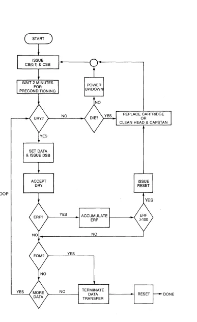
3.2.7 Append Operation
The Streamer will allow new data to be appended to existing tape data. To perform this function, the cartridge must enable Write Operation. See Section 3.1.1 for further information, if required.
To perform the Append Operation, the host sets the appropriate Command Bit for Read Operat ion, issues the Command St robe (CSB), and wa its for the PRE/EOD status signal. When PRE/EOD is reached, the host sets the appropriate Command Bit for Write Operation and issues the Command Strobe (CSB). The new data can be appended up to End of Memory (EOM).
When the Streamer is in the Read Mode and PRE/EOD is reached, the drive will automatically stop. When the drive starts again appending new data, an expanded gap of app rox i mate ly 0.07 inches will exi st. Fi gu re 3-6 illustrates a detailed flowchart of the Streamer Append Operation. The flowchart assumes successful completion of the Power-Up Sequence as covered in Section 3.2.9.
ACCEPT DATA
& DRY
ISSUE DSB
ISSUE WRITE
& CSB
TO WRITE FLOW CHART ABORT APPEND
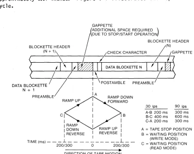
3.2.8 Repositioning Operation
The Streamer drive will stop and reset tape adjusting to a write underflow or a read overflow condition. Each time the repositioning routine is executed, the controller leaves an interblock gap of approximately 0.07 inches. Figure 3-7 illustrates the repositioning cycl e.
GAPPEITE
(ADDITIONAL SPACE REQUIRED \ DUE TO STOP/START OPERATIONI
BLOCKETTE HEADER
BLOCKEITE HEADER ~N)
(N + 1 ) \ _ (-CHECK CHARACTER 'jjG'APPETTE
~I.----il'\
I
~
II
DATA BLOCKETIE NI
J/~
' - - - - -- ; - , I - - - + - I
~---/-DATA BLOCKETTE I POST AMBLE PREAMBLE
I
N + 1
PREAMBLE IA
I I
I
CI I IB
I I I
I RAMP I I
I DOWN I
30 ips A-B 200 ms B-C 400 ms C-A 200 ms
90 ips 300 ms 600 ms 300 ms
A = TAPE STOP POSITION
I REVERSE I I B = WAITING POSITION
l.. L (WRITE MODE)
TIME(ms)--- - - C=WAITINGPOSITION 200/300 0 200/300
_ _ _ _ _ _ _ _ ~~ (READ MODE) DI RECTION OF TAPE MOTION
Figure 3-7 REPOSITIONING CYCLE
[image:46.612.67.467.160.477.2]