Some
Inquiries
Into
Special
Relativity
Borge NodlandJohns Hopkins University Applied Physics Laboratory, Laurel,Maryland 20723,USA∗
(Dated: November7,2019)
AbstractThispaperpresentsresearchwithinthetopicofspecialrelativity.First,weshowthat
timedilationandlengthcontractiondonotnecessarilyrequirethatthespeedoflightbethesamein
allreferenceframes. Itisonlynecessarytorequirethatthespeedoflightbefiniteinanyparticular
frame. Next,wedemonstratethat therelativistic Doppler shiftforelectromagneticwaveshas an
analogueforextendedmaterialobjects,andfurnishanexpressionfortherelativevelocityof such
objectsintermsofwhatwecalltheir“restlengthshift.” Analternativevelocity,whichwecall“rest
velocity,” isthen introduced tosimplifythe Lorentztransformationformulas. Wealso showthat
regular velocitycanbe regardedas thegeometric averageofthe “restvelocity” and anothertype
of velocity weterm “contracted velocity.” We conclude byformulating the relationship between
regularand“rest”velocityfornon-uniformmotioninone,two,andthreedimensions.
Keywords: physics,relativity
I. INTRODUCTION
This article presents the findings of original research within the area of special relativity. The utmost care has been taken to derive results in a clear and orderly man-ner. Hence the “textbook” look and feel of the article.
In Sections II and III we use the light clock concept to define time and length units for stationary and mov-ing reference frames. In Section III we then precisely define the relative velocityvof a reference frame (or ma-terial object) by means of the previously defined time and length units. Only aftervis thus defined, do we employ it to derive the phenomenon of time dilation.
In Section IV we note that the phenomenon of time dilation of moving clocks as observed in any particular reference frame is not strictly contingent on the speed of light being the same in all reference frames. It is only contingent on the the speed of light being finite in that particular reference frame.
In Section V we observe that the conclusion in Section IV also holds for the phenomenon of length contraction. We also show that an equivalent definition of material velocity v can be given that is entirely consistent with the previous definition in Section III.
Section VI provides a derivation of the Lorentz trans-formation based on length contraction alone.
In Section VII we derive the Lorenz factor from the consideration of two rigid rods in relative motion. If in-stead we consider the Lorentz factor as already derived from the usual Pythagorean relation, we arrive at a “rest length shift” formula for extended material objects in rel-ative motion, analogous to the relativistic Doppler shift for electromagnetic waves. By inverting this formula, we obtain an expression for the velocity of an extended ob-ject in terms of its “rest length shift.”
By introducing an alternative velocity definition, which we call “rest velocity,” the Lorentz transformation
equa-∗[email protected]
tions may be simplified so that they no longer contain the Lorentz factor radical. This is shown in Section VIII. The expression for the Lorenz factor in terms of “rest velocity” is also derived.
In Section IX, a second alternative velocity definition, which we call “contracted velocity,” is introduced and expressed in terms of regular velocity. Regular velocity is then identified as the geometric average of the two alternative velocities introduced Sections VIII and IX. The formula for the Lorenz factor in terms of “contracted velocity” is derived as well.
In Section X we extend Section VIII’s description of “rest” velocity to non-uniform motion. For this purpose, the section represents variable-speed motion of a material particle by fixed-speed motion of the endpoint of a “light ray curve” in a reference frame containing an added spa-tial axis. The endpoint of this “light ray curve” moves at the fixed speed of light c, so that variations of the particle’s speedv correspond to bends in its “light ray curve.”
In Sections XI and XII the discussion in Section X is broadened to motion in two and three spatial di-mensions, respectively. For three-dimensional variable-speed particle motion, the particle’s corresponding fixed-speed “light ray curve” unfolds (and bends) in a four-dimensional spatial frame of reference.
II. PERPENDICULAR TIME
The units for time and length have long been connected through the reference-frame-invariant speed of light c: The unit of length (the meter) is defined as the distance traveled by light during a fixed fraction n1 of the unit of time (the second), wheren= 299,792,458 [1]. So length is currently defined as a light-time, such as a “light-second” or “light-year.”
Alternatively, one could define the unit of time as the time it takes light to travel nunits of length. Here, we adopt the this alternative definition. That is, we define
time as a light-length. For example, a “light-meter” would be the time it takes light to travel one meter.
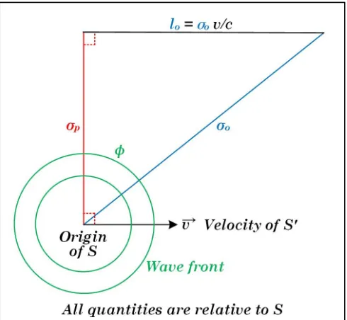
In Figure 1, there is an inertial reference frameS with orthogonal axes (x, y, z), and an inertial reference frame S0 with orthogonal axes (x0, y0, z0). These axes are not shown in the figure, to avoid clutter. The x0-axis of S0 coincides with the x-axis of S, and the y0-axis of S0 is parallel with they-axis ofS. Thex-axis andx0-axis are directed horizontally to the right. They-axis andy0-axis are directed vertically upward.
Relative to the origin ofS, the origin ofS0 is moving to the right along thex-axis at a constant velocity~v, as measured in S. S0 moves uniformly in the left-to-right direction, entering Figure 1 at its left edge and exiting at its right edge. The x-axis and x0-axis are defined to be parallel with the velocity vector ~v of S0 relative to S. The y-axis and y0-axis are similarly defined to be perpendicular to~v. Thez andz0 axes are perpendicular to the plane of the figure (thexy-plane).
FIG. 1. Light ray segments inS.
In Figure 1, we imagine there are two two-dimensional infinite flat mirrors parallel with~v and perpendicular to they-axis andy0-axis. The reflecting surface of the bot-tom mirror contains thex-axis and x0-axis. The bottom mirror lies in thexz-plane ofS and thex0z0-plane ofS0. In Figure 1, the velocity vector~v is drawn in the plane of the bottom mirror surface.
Themirror separationis the perpendicular distance σp between the reflecting surface of the top mirror and the reflecting surface of the bottom mirror. Note that there is no relative motion betweenS andS0 perpendic-ular to the mirrors.
When the origins of S and S0 coincide, let a flash of light be emitted from their common point of origin. The light radiates outward with a spherical wave front, as seen
from S, and subsequently bounces off the two mirrors indefinitely.
We now represent time intervals inSandS0in terms of the length of certain light ray segments from the flash in SandS0 by means of the concept of alight clock[2, 3]. The ticking of the light clock in S is the up-and-down propagation of light along the y-axis between the two mirrors, as seen inS. Similarly, the ticking of the light clock inS0 is the up-and-down propagation of light along they0-axis between the same two mirrors, as seen inS0. See Figure 1.
We take the unit of perpendicular lengthin S to be the length of that light ray segment, as seen from S, that originates from the origin of S at the bottom mirror, is perpendicular to the velocity~v of S0 relative toS, and terminates at the top mirror. This particular light ray segment inS is labeled “σp” in Figure 1 (the subscript “p” stands for “perpendicular”). The segment is along the positivey-axis. The length of the segment is obviously equal to the mirror separationσp. We denote the speed of light as measured inS byc. In Figure 1, we have labeled the speed of light accordingly asc.
We take theunit of perpendicular timeinS to be the time
τp= σp
c (1)
it takes for light to propagate a unitσp of perpendicular length in S. In other words, we define the unit of perpendicular timeτp as the light-length σp. Note that the perpendicular light ray segment inS is traced out by the wave front along the positivey-axis inS. Since they-axis is at rest inS, the unit of perpendicular time is theunit of rest timeinS.
When the wave front along the perpendicular segment in Figure 1 impinges on the top mirror, the wave is re-flected perpendicularly back towards the bottom mirror. The reflected wave is a spherical wave emanating from the point of impingement. The reflected wave travels down the positivey-axis, and the duration of travel from the top mirror to the bottom mirror is again the unitτp of perpendicular time inS.
A perpendicular time tick (orrest time tick) in Sis the event when the light propagating along the per-pendicular segment inS reflects off the top mirror or off the bottom mirror. The tick itself has no duration. The time elapsed between two successive perpendicular time ticks inS is the unitτpof perpendicular time in S. The perpendicular light ray continues to bounce off the two mirrors indefinitely along the positivey-axis ofS, tracing out perpendicular time inS. The rate of perpendicu-lar time(orrate of rest time) in S is the frequency
νp= 1 τp
(2)
III. OBLIQUE TIME. TIME DILATION.
Consider the wave front points from the flash at the common point of origin ofS and S0 that lie on the per-pendicular light ray segment in S0. In S0, this perpen-dicular light ray segment is along the positivey0-axis and its length is the mirror separation σp, since there is no relative motion between S and S0 perpendicular to the mirrors.
InS, the same wave front points form the oblique light ray segment labeled “σo” in Figure 1 (the subscript “o” stands for “oblique”). The obliquity is due to the motion ofS0 from left to right with uniform velocity~vrelative to S. As measured inS, the length of this oblique segment is σo. We call this length the unit of oblique length inS.
When the wave front along the oblique segment in Fig-ure 1 impinges on the top mirror, as seen from S, the origin ofS0 has moved to the right in S a distancelo to the point on the x-axis where they0-axis ofS0 contains the point of impingement, as seen fromS. Note that this definition oflo assumes thatlo is less thanσo.
For reasons that will become clear in Equation 5 below, we shall refer to lo as the fractional unit of oblique
lengthinS. We may picture the segment of the positive x-axis whose left endpoint is the origin ofS and whose length is lo as a rigid rod in S. Since this rod is at rest in S, we may also refer to lo as thefractional unit of
rest lengthin S.
We take theunit of oblique timeinSto be the time
τo= σo
c (3)
it takes for light to propagate a unitσoof oblique length in S. In other words, we define the unit of oblique timeτo as the light-length σo. Note that the oblique ray inSis traced out by the wave front along the positive y0-axis in S0. Since the y0-axis is moving to the right in S, we also refer toτoas theunit of moving timeinS. We define the velocity of S0 in S to be the ratio of the fractional unit of oblique length (rest length) inSto the unit of oblique time (moving time) inS:
v=|~v|= lo τo
=clo σo
. (4)
As seen fromS, the time it takesS0to move the distance lo is τo = σco (Equation 3). v is the distance lo that S0 travels, as measured in S, divided by the timeτo of travel, also as measured inS.
From Figure 1, we see that by definition, σp, lo, and σoform the first leg, second leg, and hypotenuse, respec-tively of a right triangle. Therefore,the velocityv =clo
σo
ofS0 cannot exceedcdue to the wayv is defined. Com-pare this with the alternatively defined velocityu=clo
σp
in Equation 32, which can exceedc. From Equation 4,lois given by
lo=vτo=σo v
c. (5)
Equation 5 shows that lo is equal to the unit σo of oblique length times the velocity fraction vc. This is the reason for callinglothe fractional unit of oblique length. Equation 5 also shows thatlo is equal to the velocityv ofS0 inS times the unitτ
o of moving time inS. According to the right-triangle relation (Pythagorean relation) for the right triangle of lengths in Figure 1 for S, we have
σp2+l2o=σ2o. (6)
Substitution of Equation 5 into Equation 6 and solving for v
c gives
v c =
s
1−σ 2
p σ2
o
. (7)
We define theobliquity factorinS to be the ratio
γ= σo σp
(8)
of the unit of oblique length to the unit of perpendicular length inS.
Solving 7 for the obliquity factor, we get
γ= σo σp
= q 1 1−v2
c2
, (9)
which is of course the familiar Lorentz factor [4]. From Equation 9, we have
σo=γσp= σp q
1−v2
c2
. (10)
From Equation 10, we see that the unit of oblique length inS is a factor ofγ longer than the unit of per-pendicular length inS. When dividing Equation 10 byc and using Equations 1 and 3, we obtain
τo= σo
c =γ σp
c =γτp. (11)
So the unit τo of moving time in S is a factor of γ longer than the unit τp of rest time in S. This is the familiartime dilationresult: The elapsed time, as seen fromS, between two successive time ticks of a light clock at the origin ofS0 is a factor ofγlonger than the elapsed time, as seen fromS, between two successive time ticks of a light clock at the origin ofS.
We define the obliquity angle in S as the angle φ that the oblique light ray segment “σo” makes with the perpendicular light ray segment “σp,” as seen fromS in Figure 1.
From the right triangle in Figure 1, we see that φ is given by
sinφ= lo σo
= v
or equivalently by
cosφ= σp σo
= 1
γ. (13)
When the wave front along the light ray segment la-beled “σo” in Figure 1 impinges on the top mirror, the ray is reflected obliquely back towards the bottom mir-ror. The reflected wave is a spherical wave emanating from the point of impingement. The oblique reflected ray makes the angleφ with the perpendicular. This oblique reflected ray is not shown in Figure 1, to avoid clutter. When the wave front along the oblique reflected ray im-pinges on the bottom mirror, as seen from S, the origin of S0 has moved to the right a distance lo again to the point on the x-axis where the origin of S0 contains the point of impingement, as seen fromS. Relative toS, the duration of travel of the oblique reflected ray from the top mirror to the bottom mirror is again the unit τo of oblique time inS.
Anoblique time tick(or moving time tick) in S is the event when the light propagating along an oblique segment in S reflects off the top mirror or off the bot-tom mirror. The tick itself has no duration. The time elapsed between two successive oblique time ticks inS is the unit τo of oblique time in S. The oblique light ray continues to zigzag between the two mirrors indefinitely at a net horizontal velocity~v relative to S, tracing out oblique time in S. Therate of oblique time(or rate of moving time) in S is the frequency
νo= 1 τo
(14)
of oblique time ticks inS.
IV. LIGHT SPEED FINITUDE
If c were infinite instead of finite in some reference frame, light would traverse any distance in no time, i.e., time would not exist in this reference frame. We owe the existence of time to the fact that c is finite in any particular reference frame. We may refer to this property of electromagnetic radiation aslight speed finitude.
IfS0travels to the right at velocityvrelative toS, then S travels to the left at velocityvrelative to S0. We may call this factframe speed reciprocity. We also know that the speedcof light inS is the same as the speed of light inS0, which we may calllight speed invariance. Note that it is not necessary to assume frame speed reciprocity or light speed invariance to deduce the exis-tence of time dilation in any particular reference frame S. One only needs to assume light speed finitude inS. Frame speed reciprocity and light speed invariance are only required to deduce that the amountγ of time dila-tion is the same in both S and S0, a property we may calltime dilation reciprocity.
In Figure 1, light speed finitude means the wave along the perpendicular light ray segmentσpinSand the wave
along the oblique light ray segmentσo in S both travel at the same finite speedc. The oblique segment is longer than the perpendicular segment, so it takes light longer to travel along the oblique segment than along the per-pendicular segment. This is the reason for time dilation.
V. LENGTH CONTRACTION
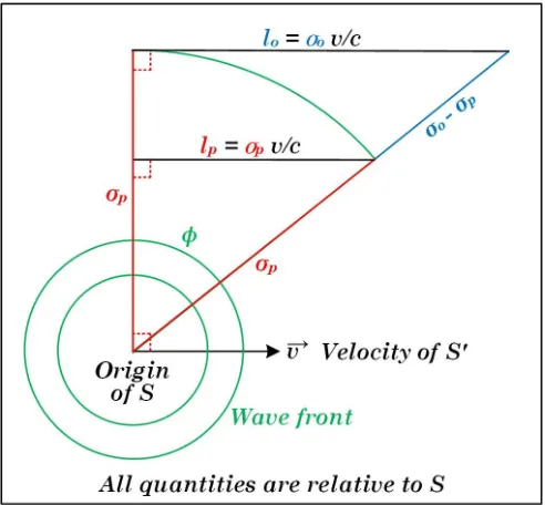
Assume there is a rigid rod stationary in S0 along the negativex0-axis with its right endpoint at the origin of S0. The rod is thus moving with uniform velocity v to the right across the stationary light clock at the origin of S, as seen fromS.
We determine the elapsed time, according to the sta-tionary light clock inS, between the instance inS when the rod’s right endpoint is at the origin ofS and the in-stance inSwhen the rod’s left endpoint is at the origin of S. This elapsed time will be the unitτpof perpendicular time (i.e., rest time) inS multiplied by a certain number of perpendicular time ticks inS.
For simplicity, let’s assume that the length of the rod is such that the elapsed time measured by the stationary light clock in S is exactly the unit τp of perpendicular time inS. The length of the moving rod, as measured in S, is then
lp=vτp=σp v
c. (15)
Equation 15 shows that lp is equal to the unit σp of perpendicular length times the velocity fraction vc. We may therefore call lp the fractional unit of
perpen-dicular length. Since the rod is moving inS, we may also calllpthefractional unit of moving lengthinS. The rod moving past a light clock at a velocity v rel-ative to the light clock is equivalent to the light clock moving past the rod at a velocityv relative to the rod. So we now assume that the same rod is stationary inS and lies along the positive x-axis with its left endpoint at the origin ofS. The light clock inS0 is now moving with uniform velocityvto the right across the stationary rod, as seen fromS.
We determine the elapsed time, according to the mov-ing light clock, between the instance inSwhen the origin ofS0 is at the rod’s left endpoint and the instance inS when the origin ofS0is at the rod’s right endpoint. This elapsed time will be the unitτoof moving time inS. The length of the stationary rod, as measured inS, is then given by Equation 5, and as stated before, the fractional unitloof rest length inSis the velocityvofS0inStimes the unitτo of moving time inS.
FIG. 2. Length contraction inS.
Since the fractional unitlpof moving length inSis the fraction v
c times the unit σp of perpendicular length in S (Equation 15), and the fractional unitlo of rest length in S is the same fraction vc times the unit σo of oblique length inS(Equation 5), we may also callσptheunit of
moving length in S, andσo theunit of rest length inS.
Note thatσo is the unit of rest length andτo= σco is the unit of moving time, whereasσpis the unit of moving length andτp=
σp
c is the unit of rest time.
Equation 15 can be viewed as an alternative definition of the velocityv ofS0 inS:
v= lp τp
=clp σp
. (16)
This definition is obviously equivalent to the definition given by Equation 4, because the two right triangles in Figure 2 are similar (proportional). So v is oblique length (rest length) over oblique time (moving time), or perpendicular length (moving length) over perpendicular time (rest time).
Due to time dilation (Equation 11), the timeτoit takes for the origin ofS0 to move across the rod, as seen inS, is longer by a factor of γ than the time τp it takes for the rod to move across the origin ofS, as seen in S. If we multiply Equation 11 byv, Equations 5 and 15 show that
lo=vτo=γvτp=γlp. (17)
So the fractional unit lo of rest length inS is a factor of γ longer than the fractional unitlp of moving length in S. This is the familiar length contraction result: The distance the origin of S0 travels along the x-axis
between two successive time ticks, as seen from S, of a light clock at the origin of S0 is a factor of γ longer than the distance the origin ofS0travels along thex-axis between two successive time ticks, as seen fromS, of a light clock at the origin ofS.
Just as for time dilation, it is not necessary to assume frame speed reciprocity or light speed invariance to de-duce the existence of length contraction in any particular reference frameS. One only needs to assume light speed finitude inS. Frame speed reciprocity and light speed invariance are only required to deduce that the amount γ of length contraction in S is equal to that in S0, a property we may calllength contraction reciprocity.
VI. SPACETIME TRANSFORMATION
We assume a rigid rod is at rest along the positivex0 -axis inS0, has its left endpoint at the origin of S0, and has a rest length ofx0. x0 is thus the location of the rod’s right endpoint, as seen inS0. As in Figure 1, we assume the origin of S0 moves to the right along the x-axis in S with constant velocity v, as seen from S. We define t to be the time elapsed inS after the origins ofS andS0 coincided. tis the elapsed rest time inS.
Due to light speed finitude, the moving rod undergoes length contraction inS. As seen from S therefore, the locationxof the right endpoint of the rod after the time intervalthas elapsed is the moving length x0
γ of the rod (Equation 17) plus the distancevt the rod has traveled to the right during the time intervalt:
x=x 0
γ +vt. (18)
Solving this equation forx0, we get
x0 =γ(x−vt). (19)
We now instead assume the same rigid rod is at rest along the positive x-axis in S, has its left endpoint at the origin of S, and has a rest length of x. x is thus the location of the rod’s right endpoint, as seen in S. Relative toS0, the origin ofSmoves to the left along the x0-axis in S0 with constant velocity v, as seen from S0. We definet0to be the time elapsed inS0after the origins ofS andS0 coincided. t0 is the elapsed rest time inS0.
Due to light speed finitude, the moving rod undergoes length contraction in S0. We now impose frame speed reciprocity and light speed invariance. As seen fromS0 therefore, the locationx0 of the right endpoint of the rod after the time intervalt0 has elapsed is the moving length x
γ of the rod (Equation 17) minus the distancevt
0the rod
has traveled to the left during the time intervalt0:
x0=x γ −vt
Solving this equation forx, we get
x=γ(x0+vt0). (21)
By substituting the expression for x in Equation 18 into Equation 20 and then solving for t (while making use of Equation 9), we get
t=γ(t0+vx 0
c2 ). (22)
Equations 21 and 22 define the familiar spacetime transformation(Lorentz transformation) fromS0 toS. We see that it is necessary to assume frame speed reci-procity and light speed invariance to deduce the space-time transformation (Equations 21 and 22). It is not sufficient to only assume light speed finitude.
VII. REST LENGTH SHIFT
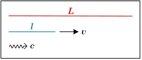
Consider two parallel rigid rodsRandrof rest lengths Landl respectively. Without loss of generality, we take l < L. Letrmove to the right with speedvrelative toR. See Figure 3. When the rods’ left ends are aligned, let a flash of light be emitted from the left alignment point. This is indicated by the photon in Figure 3.
FIG. 3. Rest length shift.
We takevto be the speed required for the right ends of the rods to be aligned when the photon reaches the right alignment point. Note that the required speedv < ccan always be found for anyLand any l < L.
In the rest frame of R, the time elapsed between the event of the rods’ left ends being aligned to the event of the rods’ right ends being aligned is Lc. In this time, r has traveled a distancevLc. We set the “moving length” ofr (length of ras measured in the rest frame of R) to be the rest lengthlofrtimes some (yet unknown) factor
1
γ. Then
L= 1 γl+v
L
c, (23)
or
l
γ =L(1− v
c). (24)
In the rest frame ofr,Ris moving to the left with the same speedv(due to frame speed reciprocity). The speed of light in the rest frame ofr is the same as that in the rest frame ofR(due to light speed invariance). The time elapsed between the event of the rods’ left ends being aligned to the event of the rods’ right ends being aligned is therefore cl. In that time,Rhas traveled a distancevcl to the left. Because of frame speed reciprocity, we may set the “moving length” ofR (length of R as measured in the rest frame ofr) to be the rest length LofRtimes the same factor γ1. Then
l= 1 γL−v
l
c, (25)
or
L
γ =l(1 + v
c). (26)
When multiplying Equations 24 and 26, we get
Ll
γ2 =lL(1− v2
c2). (27)
γis thus the familiar length contraction factor (Lorentz factor) of Equation 9.
The argument above holds for any rest lengths Land l < L, and therefore for any relative speeds v. Thus, length contraction is again proved (in a manner different from that of Section V): The “moving length” of rodRis
shorter than its rest lengthLby the factor 1γ = q
1−v2
c2.
Similarly, the “moving length” of rod r is shorter than its rest lengthl by the same factor 1
γ.
By substituting Equation 9 into Equation 24 and then squaring the result, we get
l2(1−v 2
c2) =L 2(1
−v
c)
2, (28)
or
l2(1 +v c) =L
2(1−v
c). (29)
Solving Equation 29 for Ll yields
L l =
s 1 +vc 1−v c
. (30)
L
l (>1) is the rest length ofRin units of the rest length of r. Equation 30 is the familiar wavelength shift (Doppler shift) expression: Assume the light source is attached to R’s left end and a light detector is attached tor’s right end. If l is the wavelength of the flash of light as seen fromR’s rest frame, thenLis the wavelength of the same flash as seen fromr’s rest frame.
Solving Equation 29 for vc yields
v c =
L2−l2 L2+l2 =
(L l)
2−1
Equation 31 expresses the relative velocityvin terms of the “rest length shift” Ll it generates. The functional dependence ofv on Ll is graphed in Figure 4.
FIG. 4. Dependence ofvonL/l.
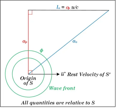
VIII. REST VELOCITY
Equation 4 defines the velocity v of S0 in terms of oblique length and time, while Equation 16 equivalently definesvin terms of perpendicular length and time. Let’s now define a new velocity in terms of oblique length and perpendicular time. We label ituand call itrest veloc-ity, to distinguish it from the previously defined velocity v:
u=|~u|= lo τp
=clo σp
. (32)
Figure 5 depicts howu is defined. WhenS0 has moved the distance lo in S, the unit τo = σco (Equation 3) of moving time in S has elapsed, and the unit τp =
σp
c (Equation 1) of rest time inS has elapsed. To compute u, an observer inS must dividelo by the rest time unit τprather than the moving time unit τo.
From Figure 5, we see that lo and σp are both legs in a right triangle. Therefore, the rest velocity uof S0 can exceedc due to the wayuis defined. Compare this with the regular velocityvdefined in Equations 4 and 16. Note that by definition,σp,lo, andσostill form the first leg, second leg, and hypotenuse, respectively of a right triangle. That is,lois still defined to be less thanσo.
From Equation 32, the fractional unit of rest lengthlo inS is now given by
lo=uτp=σp u
c. (33)
The right-triangle relation (Equation 6) still holds. Substitution of Equation 33 into Equation 6 and
solv-FIG. 5. Rest velocity~u.
ing for uc gives
u c =
s σ2
o σ2
p
−1. (34)
Solving 34 for the obliquity factor γ = σo
σp (Equation
8), we get
γ= σo σp
= r
1 + u 2
c2. (35)
This expression is of course just the familiar Lorentz fac-tor in Equation 9, expressed in terms ofuinstead ofv.
From Equation 35, we have
σo=γσp =σp r
1 +u 2
c2. (36)
Just like Equation 10, Equation 36 expresses the phe-nomenon of time dilation: The elapsed time, as seen from S, between two successive time ticks of a light clock at the origin ofS0 is a factor of γ longer than the elapsed time, as seen fromS, between two successive time ticks of a light clock at the origin ofS.
If we divide Equation 4 by Equation 32 and compare with Equation 8, we see that
v= u
γ. (37)
If we substitute Equation 35 into Equation 37, we get the following expression forv in terms ofu:
v= q u 1 + u2
c2
Equation 38 shows thatv cannot be superluminal even ifuis superluminal.
If we substitute Equation 9 into Equation 37, we get the following expression foruin terms ofv:
u= q v 1−v2
c2
. (39)
Equation 39 shows that uis luminal when v is √c 2, and becomes superluminal when v exceeds √c
2. The func-tional dependence of the rest velocity u on the regular velocityv is graphed in Figure 6.
FIG. 6. Dependence ofuonv
By multiplying Equations 38 and 39, we see that the fundamental relationship betweenvanduis
(1−v 2
c2)·(1 + u2
c2) = 1. (40)
Equation 37 lets us write the spacetime transformation equations 21 and 22 as
x u =
x0 v +t
0 (41)
and
t u =
t0 v +
x0
c2. (42)
We see of course that the price for the removal of the Lorentz factorγ (Equation 8) is the introduction of the rest velocityu.
IX. CONTRACTED VELOCITY
Equation 32 defines the rest velocity uofS0 in terms of oblique length and perpendicular time. Let’s now de-fine yet another velocity in terms of perpendicular length and oblique time. We label itq and call itcontracted velocity, to distinguish it from the previously defined velocitiesv andu:
q=|~q|= lp τo
=clp σo
. (43)
Figure 7 depicts the definition of q. q is the length-contracted distancelpthat S0 travels, as measured inS, divided by the timeτo of travel, as measured inS.
FIG. 7. Contracted velocity~q.
From Figure 7, we see thatlpis restricted geometrically to be less than σo. Therefore, the velocity q of S0 is
less thancdue to the wayqis defined. Compare this with the restricted velocityvdefined in Equations 4 and 16, and the unrestricted velocityu defined in Equation 32.
If the length of the vertical leg of the small triangle in Figure 7 is denoted byL, then the right-triangle relation for the small triangle is
L2+l2p=σp2. (44)
From Figure 7, we see that the vertical legs of the small and large triangle are in the same ratio as their hypotenuses:
L σp
= σp σo
. (45)
Therefore
L=σ 2
p σo
. (46)
From Equation 43, the fractional unit of moving length lp inS is now given by
lp=qτo=σo q
c. (47)
Substitution of Equations 46 and 47 into Equation 44 and solving for qc gives
q c =
σp σo
s
1−σ 2
p σ2
o
The square of Equation 48 is
q2 c2 =
σ2
p σ2
o
−(σ
2
p σ2
o
)2. (49)
By viewing Equation 49 as a quadratic equation in σ
2 p
σ2 o
and solving for σ
2 p
σ2
o, we obtain the following expression
for the obliquity factorγ= σo
σp (Equation 8) in terms of
the contracted velocityq:
γ=σo σp
=r 1
1 2±
q
1 4−
q2
c2
. (50)
We see from the innermost radical in Equation 50 thatq cannot exceed c
2.
From Equations 7 and 8, we see that Equation 48 re-latesqtov as follows:
v=γq. (51)
This is also seen by dividing Equation 16 by Equation 43, and comparing the result with Equation 8. Whenq attains its maximum value of c
2, γ = √
2 (as seen from Equation 50), andv = √c
2 (as seen from Equation 51). The dependence of the contracted velocityq on the reg-ular velocityv is illustrated in Figure 8.
FIG. 8. Dependence ofq onv
By substituting Equation 51 into Equation 37, we get the following expression for the rest velocity uin terms of the contracted velocityq:
u=γ2q. (52)
By multiplying Equations 37 and 51, we see thatv is the geometric average of uand q:
v=√uq. (53)
This is also seen by multiplying Equations 4 and 16, and comparing the result with Equations 32 and 43.
X. NON-UNIFORM MOTION
The mirrors in Figures 1, 2, 5, and 7 are of course only a construct that allows us to count time ticks. We may dispose of the mirrors and let the the light wave from the flash of light propagate indefinitely outward. The perpendicular light ray segment inS (along the positive y-axis) now grows longer and longer, and the oblique light ray segment inSlikewise grows longer and longer as time passes. The length of either segment is the radius of the expanding spherical wave front surface from the flash in S.
Expressed as a light-length, elapsed perpendicular time (rest time) inSis the length of the growing perpendicular segment as a multiple of the light-length unitσp of per-pendicular time inS, and elapsed oblique time (moving time) inS is the length of the growing oblique segment as a multiple of the light-length unitσo of oblique time inS. Sinceσo> σp, and both growing segments have the same length in S (i.e., they are the radius of the same wave front sphere in S), oblique time (moving time) in Sproceeds slower than perpendicular time (rest time) in S. This is of course the phenomenon of time dilation.
Let us now assume that the origin ofS0 is not in uni-form motion relative to the origin ofS, but rather moves in an arbitrary fashion (including acceleration and decel-eration) along thex-axis. The growing oblique light ray segment in the xy-plane in S must then be modified to be alight ray curve in the xy-plane, and the curve’s endpoint must move as follows: (1) the perpendicular projection of the endpoint onto thex-axis is the origin of S0, and (2) the speed of the endpoint in thexy-plane is c. Figure 9 depicts this situation.
FIG. 9. Light ray curve inS.
ofy, in the sense that for any particular value ofy, there is one and only one value ofx. This meansthe light ray curve fully determines the motion of the origin of
S0 along the x-axis. Note that since the endpoint of the light ray curve moves at a fixed speedc, a change in v corresponds to a bend of the light curve.
The y-axis is always perpendicular to the motion of the origin ofS0. The length unit of they axis is the rest time light-length unitσp. We may call this perpendicular axis the light axis. The light axis is a spatial axis that represents time as a light-length.
In Figure 9, the length of the light ray curve traced out by the endpoint is denoted by s, and the perpendicular projection of the curve onto they-axis is denoted by y. Bothsandyare lengths measured relative toS. In terms of rest time ticks inS, rest time elapsed inS is sc, while moving time elapsed inSis yc. Sinceyis always less than s, moving time inS proceeds slower than rest time inS, which is of course a manifestation of time dilation inS.
Equation 4 defines the uniform velocity v of the ori-gin ofS0 along the x-axis. The corresponding instanta-neous velocityis
v=cdx
ds. (54)
For uniform motion,dxds = sinφ, and Equation 54 reduces to Equation 12.
The differential version of the right-triangle relation (Equation 6) is
(ds)2= (dx)2+ (dy)2. (55)
Solving Equation 55 for ds
dy, we get
ds dy =
s 1 + (dx
dy)
2. (56)
By the chain rule,
dx ds =
dx dy ·
dy
ds. (57)
For uniform motion, Equation 57 is simply
lo σo
= lo σp
·σp
σo
, (58)
which Equations 4, 8, and 32 show is the same as Equa-tion 37. From EquaEqua-tions 54, 56, and 57, v can be ex-pressed as
v= c
dx dy q
1 + (dxdy)2
. (59)
For uniform motion, dxdy = tanφ, and Equation 59 again reduces to Equation 12.
Equation 32 defines the uniform rest velocityuof the origin ofS0along thex-axis. The corresponding instan-taneous rest velocityis
u=cdx
dy. (60)
Equation 60 shows that, for uniform motion, Equation 59 reduces to Equation 38.
Equation 8 defines the (uniform) obliquity factor γ. The correspondinginstantaneous obliquity factoris
γ= ds
dy. (61)
γis the derivative of moving time light-lengthswith re-spect to rest time light-length y. For uniform motion,
ds dy =
1
cosφ, and Equation 61 reduces to Equation 13. Equations 54, 60, and 61 confirm that, for uniform mo-tion, Equation 57 reduces to Equation 37.
Let’s divide Equation 61 bycand write it as a relation between the differentials dsc and dyc:
ds c =γ
dy
c . (62)
Equation 62 is just just the differential counterpart to the time dilation relation of Equation 11. We may call ds
c theoblique time (moving time) differential, and dy
c theperpendicular time (rest time) differential. If we divide Equation 62 by the differential dx, and then use Equations 54 and 60, we get
1 v =γ
1
u, (63)
which of course is just Equation 37 for the case whenv andu are instantaneous velocities. We may calldx the
fractional oblique length (fractional rest length) differential.
XI. MOTION IN TWO DIMENSIONS
Up until this point, the motion of the origin ofS0 has only been along thex-axis of S. Let’s add motion along thez-axis ofS. In Figures 1, 2, 5, 7, and 9, thez axis is perpendicular to the plane of the figure, and the positive z-direction is towards the reader.
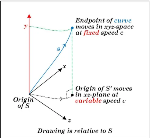
We assume that the origin ofS0 moves in an arbitrary fashion (including acceleration and deceleration) in the xz-plane. The light ray curve in thexy-plane of Figure 9 must then be modified to be a light ray curve in the xyz-space, and the curve’s endpoint must move as follows: (1) the perpendicular projection of the endpoint onto the xz-plane is the origin ofS0, and (2) the speed of the endpoint in thexyz-space isc. Figure 10 depicts this situation.
FIG. 10. Light ray curve for 2D motion inS.
The light ray curve is now a single-valued vector func-tion ofy, in the sense that for any particular value ofy, there is one and only one value of the pair (x, z). This meansthe light ray curve fully determines the mo-tion of the origin ofS0 in the xz-plane.
Theinstantaneous velocityv(Equation 54) now be-comes a planar vector~v= (vx, vz) in thexz-plane, with components
vx=c dx
ds, vz=c dz
ds. (64)
Note thatdsis now a light curve segment in three dimen-sions, whereas in Equation 54 it is a light curve segment in two dimensions only.
The differential right-triangle relation (Equation 55) becomes
(ds)2= (dx)2+ (dz)2+ (dy)2. (65)
Solving Equation 65 for dsdy, we get
ds dy =
s 1 + (dx
dy) 2+ (dz
dy)
2. (66)
By the chain rule,
dx ds =
dx dy ·
dy
ds, (67)
dz ds =
dz dy ·
dy
ds. (68)
So from Equations 64 and 66, the components of ~v = (vx, vz) can be expressed as
vx=
cdxdy
q
1 + (dxdy)2+ (dz dy)2
, (69)
vz =
cdzdy
q
1 + (dxdy)2+ (dz dy)2
. (70)
The instantaneous rest velocity u (Equation 32) similarly becomes a planar vector ~u = (ux, uz) in the xz-plane with components
ux=c dx
dy, uz=c dz
dy. (71)
The definition for theinstantaneous obliquity fac-torγfor motion in thexz-plane is still
γ= ds
dy, (72)
as in Equation 61, with the caveat thatdsis now a light curve segment in three dimensions instead of two dimen-sions.
Equations 64, 71, and 72 show that Equations 67 and 68 can be written as the planar vector equation
~ v= ~u
γ = ~ u q
1 +|~uc2|2
, (73)
which is the extension of Equations 37 and 38 to motion in two dimensions.
XII. MOTION IN THREE DIMENSIONS
We now assume that the origin ofS0moves in an arbi-trary fashion (including acceleration and deceleration) in the three-dimensionalxyz-space. This requires us to em-ploy a 4-dimensional space with four independent axes. We label the fourth axis asw. We take they-axis to be a third spatial axis equivalent to thexand z axes, and take the w-axis be the light axis. Note again that the light axis is also a spatial axis, but “special” in that it represents time as a light-length.
The light ray curve in thexyz-space of Figure 10 now becomes a light ray curve in the xyzw-space, and the curve’s endpoint moves as follows: (1) the projection par-allel to thew-axis of the endpoint onto thexyz-space is the origin ofS0, and (2) the speed of the endpoint in the xyzw-space isc. Figure 11 depicts this situation.
In Figure 11, the length of the light ray curve traced out by the endpoint in the 4-dimensional xyzw-space is denoted bys. There are 6 planes total in thexyzw-space: xy, xz, yz, xw, yw, and zw. In order to visualize them in three dimensions, the planes cannot be perpendicular. Instead, we visualize them as being at a 60◦angle to each other. Figure 11 does not depict the 6 planes, to avoid clutter.
FIG. 11. Light ray curve for 3D motion inS.
determines the motion of the origin of S0 in the
xyz-space.
Theinstantaneous velocityv(Equation 64) now be-comes a spatial vector~v = (vx, vy, vz) in the xyz-space, with components
vx=c dx
ds, vy=c dy
ds, vz=c dz
ds. (74)
Note thatdsis now a light curve segment in four dimen-sions, whereas in Equation 64 it is a light curve segment in three dimensions only.
The differential right-triangle relation (Equation 65) becomes
(ds)2= (dx)2+ (dy)2+ (dz)2+ (dw)2. (75)
Solving Equation 75 for dwds, we get
ds dw =
r
1 + (dx dw)
2+ (dy dw)
2+ (dz dw)
2. (76)
By the chain rule,
dx ds =
dx dw ·
dw
ds, (77)
dy ds =
dy dw ·
dw
ds, (78)
dz ds =
dz dw ·
dw
ds. (79)
So from Equations 74 and 76, the components of ~v = (vx, vy, vz) can be expressed as
vx=
cdwdx q
1 + (dx dw)
2+ (dy dw)
2+ (dz dw)
2
, (80)
vy =
cdwdy q
1 + (dwdx)2+ (dy dw)2+ (
dz dw)2
, (81)
vz =
cdz dw q
1 + (dwdx)2+ (dy
dw)2+ ( dz dw)2
. (82)
The instantaneous rest velocity ~u = (ux, uz) (Equation 71) similarly becomes a spatial vector ~u = (ux, uy, uz) in thexyz-space with components
ux=c dx
dw, uy=c dy
dw, uz=c dz
dw. (83)
The definition for theinstantaneous obliquity fac-torγfor motion in thexyz-space becomes
γ= ds
dw, (84)
wheredsis a light curve segment in four (spatial) dimen-sions.
Equations 74, 83, and 84 show that Equations 77, 78, and 79 can be written as the spatial vector equation
~ v= ~u
γ = ~ u q
1 +|~uc2|2
, (85)
which is the extension of Equation 73 to motion in three dimensions.
XIII. CONCLUSIONS
We have determined that the least restrictive condition for time dilation and length contraction in a particular reference frame is that the speed of light be finite in that particular frame. This condition is a subset of the pos-tulate of light speed invariance.
We also considered the relative motion of two rigid rods, and concluded that a concept analogous to the Doppler shift for electromagnetic waves may be applied to the relative motion of extended objects. Such a “rest length shift” concept may be used to determine the rel-ative velocity of extended objects in terms of such a “shift.” To make this concrete, we furnished the explicit formula for relative velocity in terms of this “shift.”
We also found that one may employ two alternative velocity definitions to simplify the Lorentz transforma-tion formulas. Regular velocity is the geometric average of these two alternative velocities.
[1] H. Barrell, “Thirteenth general conference of weights and
measures,” Physics Bulletin20, 61 (1969).
[2] A. Michelson and E. Morley, “On the relative motion of the earth and the luminiferous ether,” American Journal
of Science34, 333 (1887).
[3] G. Lewis and R. Tolman, “The principle of relativity, and
non-newtonian mechanics,” Proceedings of the American
Academy of Arts and Sciences44, 709 (1909).
[4] H. A. Lorentz, “Electromagnetic phenomena in a system moving with any velocity smaller than that of light,”