warwick.ac.uk/lib-publications
Original citation:
Rout, Bapin Kumar, Brooks, G. A., Li, Zushu, Rhamdhani, A., Schrama, Frank N. H. and
Overbosch, A. (2018) Dynamic modelling of BOF process : comparison of model performance
with the plant data. In: AISTech 2018 - The Iron and Steel Technology Conference and
Exposition, Pennsylvania Convention Centre, Philadelphia, PA., USA, 7-10 May 2018
Permanent WRAP URL:
http://wrap.warwick.ac.uk/100299
Copyright and reuse:
The Warwick Research Archive Portal (WRAP) makes this work by researchers of the
University of Warwick available open access under the following conditions. Copyright ©
and all moral rights to the version of the paper presented here belong to the individual
author(s) and/or other copyright owners. To the extent reasonable and practicable the
material made available in WRAP has been checked for eligibility before being made
available.
Copies of full items can be used for personal research or study, educational, or not-for-profit
purposes without prior permission or charge. Provided that the authors, title and full
bibliographic details are credited, a hyperlink and/or URL is given for the original metadata
page and the content is not changed in any way.
A note on versions:
The version presented here may differ from the published version or, version of record, if
you wish to cite this item you are advised to consult the publisher’s version. Please see the
‘permanent WRAP URL’ above for details on accessing the published version and note that
access may require a subscription.
Dynamic modelling of BOF process: Comparison of model performance with the plant data
B.K. Rout 1, G.A. Brooks 1, Z. Li 2, A. Rhamdhani1, Frank N. H. Schrama3 and A. Overbosch3
1Department of Mechanical and Product Design Engineering, Swinburne University of Technology Hawthorn, Victoria, Australia, 3122
Phone: (+61) (03) 92145672 Email:[email protected]
2WMG, University of Warwick Coventry, CV4 7AL United Kingdom
3 Tata Steel, Netherlands
Keywords: BOF, kinetics, dynamic model, process control
1. Introduction
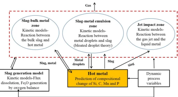
In a top blowing steel making process (BOF), the refining reactions of C, Si, Mn and P are related to several physicochemical phenomena occurring in different zones (e.g. slag-metal emulsion, jet impact zone, slag-bulk metal zone) inside the converter. In earlier publications, the authors have demonstrated a dynamic model, based on the fundamental approach of multiple zone reaction kinetics to simulate the refining of elements (C, Si, Mn and P) in a top blowing steelmaking process (BOF).[1,2] After successful model validation with the literature data from a 200 ton converter[3], simulations have been carried out to assess the model performance with the plant data. Off-line heat data obtained from a 330 ton converter at Tata Steel, Netherlands was used for the model validation. The BOF shop in Tata Steel operates with a wide range of operating and process conditions such as (i) different scrap mix, (ii) dynamic flux addition strategy, (iii) dynamic change in lance position and (iv) top and bottom flow rate. The model predictions of hot metal impurities were validated with the two sub-lance measurements and the simulated slag compositions were compared with the end blow measurements. The possible effect of the uncertainties associated with the measured (or reported) input variables in industrial conditions on the accuracy of the model calculations has been investigated. Further, the role of dynamic change in lance height and flow rate on the slag formation and the hot metal refining has been studied. The present study identifies the critical input variables required for the accuracy in the prediction of the dynamic model in plant conditions and provides a fundamental understanding to control the dynamic process variables in a BOF operation.
[image:2.595.143.486.553.741.2]2. Background of the model
The dynamic model, as mentioned in the author’s earlier publications[1,2], considers that the overall refining of a BOF process can be represented by the kinetics of reaction rates obtained from three primary zones namely (i) slag-metal-gas emulsion, (ii) jet impact and (iii) slag-bulk metal. The numerical calculation consists of three sub-modules where the rate of refining in each zone is estimated via coupling with a dynamic slag generation model to estimate the simultaneous change in bath and slag concentration at each time step. The mathematical formulation for the rate equation in each reaction zone was based on the fundamental process understandings such as refining through metal drops in the emulsion, gas-metal by gas jet and slag-metal interaction at slag-bulk metal zone. A method of oxygen mass balance in combination with lime and dolomite dissolution model was used to calculate the dynamic evolution of slag during the refining period. Figure 1 illustrates the schematic of the multi-zone kinetic model applied for modelling of the BOF process. The detailed mathematical approach has been described elsewhere. [1]
[image:3.595.74.505.206.362.2]3. Dynamic model inputs and assumptions
Table 1: An example heat of BOF operation at Tata Steel, Netherlands Furnace Parameters Values/Descriptions
Capacity
Hot metal composition Scrap
Top lance Oxygen flow rate Bottom blowing Flux addition Coolant
Measurement system
330 ton
290 ton, C-4.5%, Si-0.4%, Mn-0.3%, P-0.05%, Ti-0.06%, V-0.06%
70 ton Six hole 900 Nm3/min Yes (Ar/N2)
Lime, burnt dolomite, raw dolomite, recycled slag
Iron ore
Sublance, Off gas
A typical heat of BOF operation at Tata Steel and the operating variables are illustrated in Table 1. The furnace operates with combined blowing facility (both top oxygen and bottom inert gas injection). About 15 to 35% of solid scrap is charged before the beginning of the blow and other flux materials such as lime, dolomite and recycled slag are added in batches during the blowing period. The information regarding the initial inputs and the dynamic inputs of flux addition, lance position and gas flow rate are made available in the automation system and are collected for the model validation. About 10 sets of heat data were selected and the input variables (both initial and dynamic) as shown in Fig. 2, were given as input in each numerical simulation. Since the simulation was run in offline mode, the dynamic variables (lance height, gas flow rate, flux addition) were entered into the model calculation by using predefined functions.
[image:3.595.130.486.498.715.2]Since the model assumes that 100% of the oxygen that enters the furnace participate in the reaction, identification of all sources of oxygen input and consumption is critical for the accuracy of the iron oxide prediction. In addition to the oxygen injected by a top lance, the release of oxygen by reduction of iron ore was also included in the model calculation. Several additional sub-models such as the oxygen utilized by post combustion reaction and formation of Fe2O3 in slag were also taken into account in addition to the oxygen consumption by the oxidation reactions in the present dynamic model calculations. The kinetics of refining of hot metal elements (C, Si, Mn and P) has already been discussed in the earlier publication. [1]A schematic of the dynamic prediction of iron oxide (FetO) in the slag is illustrated in Fig. 3.
Figure 3: Method of oxygen balance to predict the dynamic evolution of iron oxide in slag
3.1.Modelling of oxygen consumed by post combustion reaction
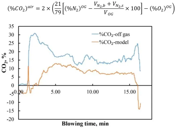
The amount of oxygen utilized for the post combustion reaction has been estimated from the measured off gas data. The quantity of air ingress through the furnace hood was calculated from N2 content in the exhaust gas, assuming that the ratio of nitrogen and oxygen in the air is 79:21. CO2 formed due to the ingressing air is given by:
(% ) = 2 × 2179 (% ) − , + , × 100 − (% ) (1)
[image:4.595.153.451.512.730.2]The symbol OG corresponds to the analyzed exhaust gas (off gas), (%CO2)air is the amount of CO2 formed due to ingress of air, VN2,b and VN2,s are the volumetric flow rate of N2 (Nm3/min) from bottom gas and lance sealing respectively. VOG represents the flow rate measured (Nm3/min) by the off gas analysis. The percentage of CO2 forming as a result of the reaction between CO and the injected oxygen gas was determined by:
[image:5.595.194.428.596.751.2](% ) = (% ) − (% ) (2)
Figure 4 shows the comparison between the CO2 produced in the converter and the CO2 measured in the off gas as a function of blowing time. It was observed that due to the ingress air infiltration at the mouth of the converter some amount of CO oxidizes and results in higher percentage of CO2 in the exhaust gas analysis.
3.2.Modelling of oxygen consumed by ferrous oxide (FeO)
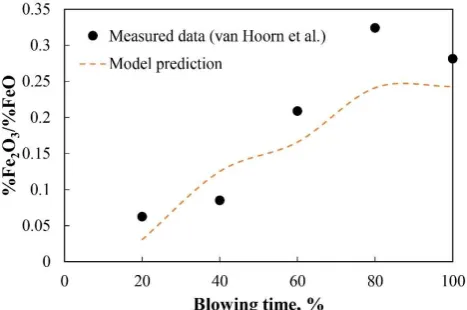
The ratio of ferric to ferrous oxide in the slag was determined by applying the following equations suggested by Darken and Gurry: [4]
%
% = + (%) (3)
Where β is experimentally determined constant and Ci is the concentration of oxides in the slag. The values of β for different slag oxide components are taken from the literature. [3] The term A expresses the value of the above ratio in pure iron oxide and is determined by applying the following equations:
= 0.8541 +296.7 (4)
= ( − 1)(3 − 2 ) (5)
= ×159.771.85 (6)
3.3.Simulation of temperature profile
Previously developed scrap melting model developed by Corus RD&T [8] was incorporated into the present dynamic model to calculate the hot metal temperature profile during the blowing process. The scrap dissolution model takes into account for the non-steady state heat conduction of the scrap and heat and mass transfer at the scrap-liquid metal interface. In the model, a parabolic temperature profile was assumed in the undissolved part of the scrap whereas an error function was applied to simulate the temperature profile of the solidified material. The detail mathematical equations used for modeling the scrap dissolution kinetics can be found elsewhere.[9] A uniform slag temperature which is 50 °C higher than the liquid metal temperature (based on the experimental measurement by Schlautmann et al.[8]) was assumed in the model calculation.
3.4.Loss of iron oxide by dust or fume
In a BOF operation, some amount of iron is lost either by spitting of iron droplets by top blown oxygen or bursting of the iron droplet by decarburization or vaporization at the hot spot. In the present work, the mathematical model proposed by Sumi et al.
was applied to quantify the amount of iron lost in the form of the dust or fume during the refining process. [10] In this model, the rate of iron oxide generated as dust particles are expressed as a function of dynamic pressure exerted by the gas jet on the hot metal surface and the carbon concentration in the bath.
= % (7)
Where Wd is the dust generation rate in kg/min, Pd is the dynamic pressure (kPa). The dynamic impact pressure on the surface of the hot metal was determined by applying an empirical correlation given by Deo and Boom.[11] The constant K has been correlated to carbon concentration based on the experimental data of Sumi et al.
4. Results
4.1. Operating process inputs of the simulated heat
The manufactured heat which was considered for the dynamic model was started by adding 83 ton of the scrap to 255 ton of hot metal. About 2 ton of lime was added before the start of the blow. Oxygen blowing was initiated after lowering the lance to a stable position of 2.5 m above the melt surface. The lance height was gradually reduced and fluxes (lime and burnt dolomite) were added continuously during the first 5 min of the blow. About 7 ton of iron ore was added in two batches during middle and end blow periods.
[image:6.595.158.456.490.736.2]4.2. Dynamic model prediction of hot metal and slag composition
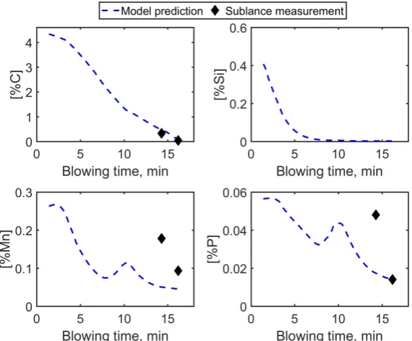
The model prediction of the concentration of C, Si, Mn and P at each one-second interval of blowing time is shown in Fig. 6. As can be seen from the figure, the simulated end blow composition (C, Mn and P) agrees reasonably with the sub-lance measurements. The simulated carbon refining path shows the characteristic three distinct regions (slow de- C at the beginning, fast in the middle and again slow at the end). The predicted phosphorus and manganese show the characteristics reversion at the time of dry slag period (low iron oxide in slag at the time of peak decarburization period).
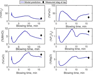
Figure 7: Evolution of slag predicted by the model
The model prediction of slag evolution during the blowing period is illustrated in Fig 7. The expected trend of slag formation has been observed. From the curves, it can be seen that in the early stage of the blow mostly the slag contains SiO2 and FeO. The evolution of iron oxide follows a high-low-high pattern and the maximum dissolution of lime takes place after 50 to 60% of the blow. The decreasing trend of P2O5 and MnO (as a result of reversion) is found to be consistent with the low FeO in the slag.
4.3
.
Comparison of model predictions with the end blow measurementsFigure 8: Comparison of the model prediction of hot metal composition with sub-lance measurements (a) In-blow measurements (b) end blow measurements
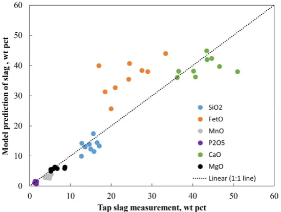
[image:7.595.63.498.486.678.2]reasonably with the in-blow measurements. The model prediction of slag was compared with the measured tap slag data and are shown in Fig. 9. As seen from the figure, all other oxide components except FeO fit reasonably well with the model predictions. However, the FeO concentration estimated by the model was found to be consistently higher than the measured values. The source of error in iron oxide predictions is discussed in the succeeding section.
Figure 9: Comparison between the model prediction and measured slag composition at the end of the blow 5. Discussions
5.1.Accuracy of oxygen balance in industrial BOF operation
To determine the potential source of error in oxygen balance, the process variables which may influence the oxygen mass balance has been investigated. A static mass balance method based on the input and output steel composition and oxygen supplied was applied to estimate the iron oxide generated during the heat. The error in iron oxide was calculated by subtracting the measured slag iron oxide from the estimated value. The following process parameters and the error associated with the reported value on oxygen mass balance and iron oxide estimation have been discussed in the below sections.
Figure 10: Error in iron oxide prediction (ΔFetO (kg) = (WFeO static mass balance- WFeOmeasured) in heat (a) Effect of hot metal Si (b) Effect of scrap/hot metal ratio
C in hot metal
[image:8.595.62.563.457.631.2]the several variables that influence the saturated carbon concentration, it was observed that the heats with high Si values introduce a large error in the prediction of iron oxide (see Fig. 10 (a)). The reason may be due to the high influence of Si on the carbon saturation equation, which results in the inaccuracy in the oxygen consumption calculation.
Post combustion ratio
Inaccuracy in the estimation of oxygen consumption by CO to form CO2 (post combustion) can lead to error in oxygen mass balance and FeO predictions. For example, the difference in iron oxide estimation (by mass balance) can be more than 3 ton if the PCR value increases from 0.1 to 0.15. Among many variables, the scrap type plays a significant role in the post combustion process, particularly in the initial stage of blowing. Figure 10 (b) shows the plot of error in iron oxide calculated by the mass balance with scrap to hot metal ratio. A positive trend of error in iron oxide with an increase in scrap ratio has been observed. It may be inferred that the error in PCR estimation by the off gas measurement is high when a relatively higher amount of scrap is charged into the furnace.
Formation of ferric oxide
The model calculations show that changing the ratio Fe2O3 to FeO does not make a significant difference in the total iron oxide (FetO) in slag. For example, increasing the ratio of Fe2O3 to FeO from 0.2 to 0.3 makes a difference of 250 kg in the calculated weight of iron oxide. Therefore this variable is thought to be having negligible influence on the error in the oxygen mass balance.
5.2.Effect of post combustion ratio on early blow slag formation
Two heats with different post combustion profiles have been chosen to investigate the impact of post combustion on the iron oxide formation in slag, particularly during the initial stage of the blow. Figure 11 (a) shows the post combustion profile (after subtracting the air ingress component) of two heats. As can be seen from the figure, until about 4000 Nm3 of oxygen blown into the furnace, the post combustion ratio of heat 1 has higher values as compared to heat 2.
Figure 11 (b) shows the model prediction of the evolution of iron oxide during the initial 30% of the blowing operation with two different PCR profiles. In the initial stage the model predicted iron oxide in the slag rapidly increases and after certain time it starts to decrease due to its consumption by decarburization reaction. With the same amount of oxygen blown (and similar lance profile) into the furnace, the heat 1 shows a higher amount iron oxide being generated during the early stage of slag formation. It should be mentioned that initial inputs for these two heats are similar in Si concentration and hot metal temperature. The major differences between these two heats are the scrap to metal ratio and scrap types. In heat 1 the scrap to metal ratio was about 32% in contrast to 18% scrap was charged in heat 2. Further, the heat 1, about 90% of the light scrap has been charged. The light scrap is expected to melt quickly and decrease the temperature of the melt rapidly as compared to heavy scraps.[9] As a result, the post combustion ratio (CO+ O2->CO2) of heat 1 was observed to be lower than heat 2.
During the early blow stage, Si (in some cases Ti or V), due to its large affinity for oxygen reacts with oxygen to form its oxide. The remaining supplied oxygen reacts with other elements such as Fe, C, P, Mn and S. Due to slow rate of decarburization and low concentration of other impurities (P, Mn and S), the unreacted oxygen can be expected to be utilized to form FeO in slag. This explains a sharp rise in iron oxide predicted by the model during the start of the process. Besides these, each mole of CO2
formation consumes extra 0.5 moles of oxygen and thus decreases the amount of oxygen available for iron oxide formation. The low value of post combustion ratio during the early blow period was therefore predicted to generate high FeO in the slag as compared to the heat with high post combustion ratio. The present model results show that the interplay between the oxygen distribution between the post combustion and iron oxidation plays an important role in the early FeO formation.
[image:9.595.60.551.484.657.2]5.3.Effect of lance position and oxygen flow rate on evolution of slag and hot metal composition
Lance height
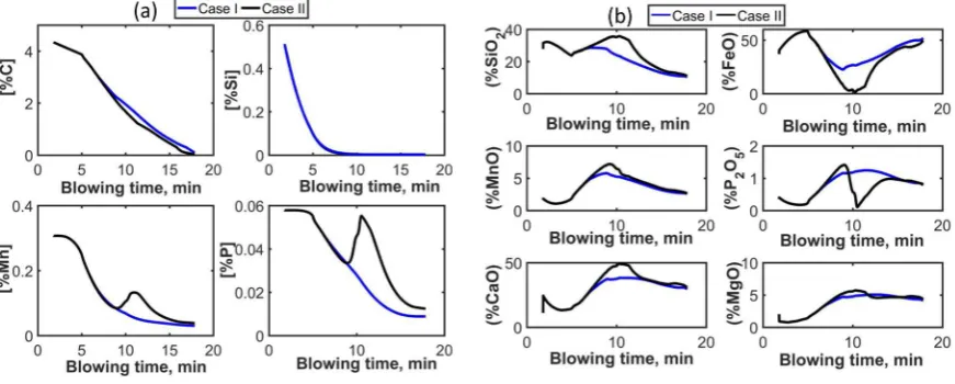
[image:10.595.103.511.213.366.2]The position of the oxygen delivering lance plays a crucial role in determining the decarburization and right slag formation during the blowing operation. The effect of lance position on the evolution of slag and hot metal refining has been studied by use of two different lance profiles. As shown in Fig. 12, in one heat the lance position has been lowered to 2.4 m above the bath after about 25% of the blow and kept constant throughout the blow period. In another heat, the lance height has been decreased by 0.1m in every 1 min of blowing interval from 25% to 55% of the blow. In both cases, the oxygen flow rate was kept constant. Model prediction of hot metal composition and slag composition evolution for two different lance profiles has been illustrated in Fig. 13. As can be seen from the figure, for the case I where the lance has been kept in a higher position, a slower decarburization rate has been observed as compared to the lower lance profile heat. As expected, the Mn and P refining in case I was found to be better with high lance position heat. The simulated results show a large reversion of Mn and P in the middle stage of the blow with a gradual decrease in lance height (case II). The point of reversion predicted by the model is consistent with the dry slag period (low FeO as shown in Fig 13. (b))
Figure 12: Lance profile used in the dynamic model calculation: (a) constant lance position (case I) (b) stepwise variation of lance position (case II)
Figure 13: Effect of change in lance position on hot metal refining (a) Hot metal composition (b) slag composition Oxygen flow rate
[image:10.595.95.531.416.591.2]6. Conclusions
The dynamic model validation was carried out with a wide range of operating conditions in an industrial converter data at Tata Steel, Netherlands. Simulated results of hot metal and slag are validated with the sub-lance measurements and end blow data. The simulation model for BOF delivered a satisfactory and comprehensive description of the process and enabled the quantitative evaluation of the slag formation and hot metal refining with a change in process parameters.
1. The current model prediction of iron oxide evolution in the slag is strongly dependent on the accuracy of oxygen mass balance. Reliable measurement of C in hot metal and evaluation of post combustion ratio are the two major parameters which are found to be responsible for the inconsistency in oxygen mass balance for the iron oxide prediction in the dynamic model.
2. Initial stage iron oxide formation in the slag is interlinked with post combustion ratio, which in turn is dependent on the scrap amount and types. A value of low post combustion ratio at the beginning was predicted to result in more FeO in the slag.
3. The model results show that decreasing the lance position during the mid-blow period worsens the P and Mn removal. A reduced oxygen flow rate was shown to have a direct impact on decarburisation rate. However, the P and Mn refining requires right slag conditions and can be manipulated by controlling the lance height, oxygen flow rate and ore addition.
Acknowledgement
The authors would like to thank Tata Steel, the Netherlands for funding this work. Helpful and valuable discussions with J. Sun, Sander Willemsen, Gert Abbel and Ding Huijuan from Tata Steel, Netherlands are greatly acknowledged.
References
1. B. K. Rout, G. Brooks, M. A. Rhamdhani, Z. Li, F. N. H. Schrama, and J. Sun, “Dynamic Model of Basic Oxygen Steelmaking Process Based on Multi-zone Reaction Kinetics: Model Derivation and Validation,” Metall. Mater. Trans. B, 2018, pp. 1-21.
2. B. K. Rout, G. A. Brooks, Z. Li, and A. Rhamdhani, “Dynamic Modeling of Oxygen Steelmaking Process : A Multi-Zone Kinetic Approach,” AISTech 2017 Proc., 2017, pp. 1315–1326.
3. C. Cicutti, M. Valdez, T. Perez, J. Petroni, A. Gomez, R. Donayo, and L. Ferro. Study of slag-metal reactions in an ld-lbe converter. In Sixth International Conference on Molten Slags, Fluxes and Salts. Stockholm-Helsinki, 2000
.
4. Dian_cai Guo. A new model of predicting phosphorus equilibrium and its applications. Steel research international, 55(5), 1984, pp. 183-188.
5. AI Van Hoorn, JT van Konynenburg, and PJ Kreyger. Evolution of slag composition and weight during the blow. The Role of Slag in Basic Oxygen Steelmaking Processes. McMaster University, Hamilton, Ontario. 1976, pp. 1-18. 6. S. Ban-Ya and J. Shim. Application of the regular solution model for the equilibrium of distribution of oxygen
[image:11.595.120.479.57.262.2]7. Eberhard Schurmann, Obst Karl-heinz, Fiege Ludwig, and Kaiser Heinz-peter. Effect of bottom stirring and post stirring on the oxygen distribution between metal and slag at the end of the LD process. 8, 1985, pp. 425-431. 8. Schlautmann M., Kleimt B., Khadhraoui S., Hack K., Monheim P., Glaser B., Antonic R., Adderley M., and Schrama
F. Dynamic on-line monitoring and end point control of dephosphorisation in the bof converter. In 3rd European Steel Technology and Application Days (ESTAD), June 2017.
9. E. Graveland-Gisolf, P. Mink, A. B. Snoeijer, E. Baker, R. Boom, D. Dixit and B. DeO . The new generation slag-droplet model. In SCANMET II: 2nd International Conference on Process Development in Iron and Steelmaking,
2004.
10. Ikuhiro Sumi, Ryo Kawabata, Yoshiteru Kikuchi, Satoshi Kohira, and Tomoo Isawa. Technique of controlling dust generation during oxygen top blowing in BOF. Steel research international, 74(1), 2003, pp. 14-18.