A Comparative Analysis between BPMN and SPEM
Modeling Standards in the Software Processes Context
Carlos Portela1, Alexandre Vasconcelos1, Antônio Silva2, Ariane Sinimbú2, Elder Silva2, Maurício Ronny2, Wallace Lira2, Sandro Oliveira2
1
Centro de Informática, Universidade Federal de Pernambuco, Recife, Brazil; 2Instituto de Ciências Exatas e Naturais, Universidade Federal do Pará, Belém, Brazil.
Email: {csp3, amlv}@cin.ufpe.br, {aandrecunhas, nanesinimbu, elderferreirass, mauricio.ronny, wallace.lira}@gmail.com, [email protected]
Received March 8th, 2012; revised April 7th, 2012; accepted May 6th, 2012
ABSTRACT
The main objective of this paper is to analyze the representativeness of the SPEM (Software Process Engineering Metamodel Specification) and the BPMN (Business Process Modeling Notation) standards in the software processes modeling context. To perform this analysis, it was adopted a standard structure to define a software process based upon a process ontology. Then, the SPEM and BPMN standards notations and their semantically corresponding elements in the default process were identified. This mapping also includes components of the CMMI-DEV (Capability Maturity Model Integration for Development) and MR-MPS (Reference Model for Software Process Improvement) quality mod- els. This was necessary to assist in the mapping evaluation through a case study which models the best practices of these quality models. Finally, we carried out an analysis of these standards through specific characteristics considered necessary to model and to represent software processes.
Keywords: Software Processes Modeling; SPEM; BPMN; Quality Models
1. Introduction
Since the earliest development projects of large software systems, a major concern of the organizations was to provide a strategy to manage the complexity of software development activities [1]. Thus, several life cycle mod- els have been proposed for software development (e.g. Waterfall, Spiral and Incremental Model). However, the granularity of these life cycle models was too high and did not describe the basic elements of the process, such as roles used [2]. Then there was the need to describe, in the processes, more information about what the organi- zations are actually doing during the development of software (e.g. adopted guidances). From this necessity arose the concept of Process Models.
A process model can be defined as a formal descrip- tion of the software development where several types of information should be integrated in order to indicate when, where, how, why and by whom the steps are per- formed [3]. The software process is Software Engineer- ing’s main study object and can be defined as the set of activities that aim to build software from a set of re- quirements [4]. The process models usage brings a unique set of advantages for organizations [5]: allows the process to be understood more easily; allows the identification of
process elements that can be improved; allows the proc-esses reuse; and supports the process management.
In order to build a software process model it is neces- sary a modeling language which defines a set of nota- tions needed to represent the elements that compose a soft- ware process [5]. There are several languages for soft- ware process modeling, highlighting: SPEM (Software Process Engineering Metamodel Specification) [6] that uses the UML (Unified Modeling Language) notations, defining a specific stereotypes set to support software process modeling; and the BPMN (Business Process Modeling Notation) [7], an approach that treats the soft- ware process as a business process, as well as other or- ganizational processes. These two languages are widely spread, largely due to the support they receive from OMG (Object Management Group) [8]—a worldwide recog- nized organization which aims to approve and maintain open standards for object-oriented applications.
of process modeling as it provides a way to represent these processes [10].
Obtaining Process Improvement Program certifica- tions adds competitive value to the organizations both in the national and international levels. These programs aim to help organizations defining and continuously improve- ing software processes. In Brazilian scenario, we high- light the MR-MPS (Modelo de Referência para Melhoria do Processo de Software) [10], a reference model for soft- ware process improvement which aims to adapt the mod- els and standards to the reality of Brazilian companies. The software development organizations looking for in- ternational visibility have adhered to already established models such as CMMI-DEV (Capability Maturity Model Integration for Development) [11]. This maturity model aims to provide guidelines for process improvement and the products and services development.
This paper has two main objectives. The first is to es- tablish a standard structure for software process. The sec- ond is the mapping between SPEM and BPMN modeling standards with process assets proposed by CMMI-DEV and MR-MPS process improvement models. This map- ping provides the basis for analyzing these modeling languages in relation to their expressiveness in software processes representation.
In addition to this introduction, Section 2 presents the related works to this research. In Section 3 we propose a mapping that shows the equivalence amongst modeling languages elements in relation to the CMMI-DEV and MR-MPS elements. In order to validate this analysis, a case study is presented in Section 4. Section 5 proposes an analysis to assess which of these languages is best suited for the representation of software processes. Fi- nally, Section 6 presents the conclusions of this paper.
2. Related Works
A proposal similar to that presented in this paper is dis- cussed in [9], which proposes the modeling of the CMMI guide concepts from the SPEM notation as a basis for software processes modeling. The goal of this proposal is to capture information on the compliance and compati- bility of CMMI in relation to SPEM, identifying the software process components and their relationships. The motivation for this paper is the composition of a software process metamodel for a PSEE (Process Software Engi- neering Environment) which allows process definitions compliant to CMMI and SPEM. However, this proposal does not evaluate the modeling languages available to justify the choice of language adopted in its metamodel.
There are two approaches that propose the automa- tized enactment of software processes development modeled after the SPEM standard [1,12]. To achieve this goal, both approaches apply model transformation tech-
niques specified in the SPEM model for a specification of thee BPMN sub-processes in order to make them ex- ecutable from the process execution language BPEL4WS (Business Process Execution Language for Web Ser- vices). One of the early stages of this process is the map- ping of SPEM and BPMN components. However, mod- els transformations impose refinement stages before they can be executed. These refinement stages demand a great effort in maintaining the mapping between models in the case of any change in the process, causing the loss of appropriate semantics.
A comparative study of several standards for processes modeling, including SPEM and BPMN, is presented in [13], and in relation to the characteristics considered ne- cessary to achieve this purpose. However, this approach presents no practical validation of the research con- ducted.
Through the mapping presented in the current paper, it is possible to observe which of these models have com- ponents that are semantically equivalent to each other. For some non-equivalent components, compliance was achieved by establishing conditions, restrictions or com- positions of more than one component of the target model. It will be further explained in the Subsection 3.2.
From the case study described in Section 4, it is possi- ble to observe a practical scenario of how the models relate to each other, allowing the extraction of relevant information to a proposal that meets the main practices and recommendations inherent to software processes within a model quality.
3. Mapping between Modeling Standards
and Quality Models
This Section aims to describe the mapping between the BPMN and SPEM notations for the CMMI-DEV and MR-MPS quality models. Subsequently, an analysis of the structural and behavioral representation of these no- tations is performed.
3.1. Standard Structure of Software Process Before performing the mapping, it is necessary to define a software process as a software process model and its diagrammatic representation. Thus, the overall structure of the composition of software processes used in this paper is based upon a model derived from an founda- tional ontology, named UFO (Unified Foundational On- tology) [14], applied in the software processes area in the ODE Project (Ontology-based software development en- vironment). This software process ontology (shown in
Figure 1) was developed to establish a common concept for software organizations exchange information regard-
dependency
Procedure reference
output input
possible adoption
Artifact Resource
Combination
Process Restrictions
Activity PatternofActivity
use has
1
1
0..1 1..*
1..* 1..*
1..*
[image:3.595.133.469.85.281.2]LifecycleModel
Figure 1. Software process model derived from ODE project [14].
According to this ontology [14], Processes are collec- tions of related activities that must be performed during the development of a product. Therefore, a Process con- sists of a structured set of Activities and all the infra- structure involved to perform them. In turn, Activities are the tasks or work that should be performed. An Activity requires Resources and can consume or produce Artifacts. An Activity can adopt a Procedure to accomplish this. This Activity can be decomposed into other Activities. The later kind of Activity are also known as Pre-Activi- ties. The concept of Activity is present in all models of software process as it generates Artifacts from input Ar- tifacts and other resources. Activities may represent any level of the process, e.g. an activity or a stage of the de- velopment process.
The people, software tools, equipment, or any other infrastructure necessary to run an Activity, are called Re- sources. Resources are mandatory elements to perform an Activity. A Resource can be a: human resource, hard- ware or software tools. A human resource, specifically, plays a role in the enactment of process activities. Finally, to restrict the execution of the activities defined in the process, there are the Restrictions that regulate the defi- nition of the software process.
3.2. Mapping
To represent each process component presented in the Subsection 3.1, we can adopt a modeling language to enable its conception and later its visualization, enact- ment and assessment. In this paper, we chose to adopt the BPMN and SPEM standards for process modeling, both maintained by OMG [8].
In order to describe the process stage and associated activities, there is the concept of LifecycleModel. This concept defines the structure and the approach to organ- ize the activities into process Phases. The Lifecycle starts when a software is designed and comes to an end when the software has been discontinued. Therefore, the Life- cycle contains a set of development activities, operations and maintenance. Aligned with this concept, there is the Combination which defines how a set of Phases of a LifecycleModel should be performed and specifies the LifecycleModel, which can be sequential or iterative.
The SPEM is a language suited for specifying and de- fining the processes and their components. The SPEM offers some representations and stereotypes to model its main elements into UML diagrams. The description of the SPEM elements can be found in [6]. Otherwise, BPMN is a notation of the business process management methodology. It is composed of a set of standard icons suitable for designing a process. The goal is to support the management of business processes for both technical users and business users. It was developed by BPMI (Business Process Management Initiative). The descrip- tion of the BPMN components can be found in [7]. The Artifacts are software products produced or con-
sumed when the activities are executed (i.e. code arti- facts, documents or software components). Procedures are well-established methods applied in order to perform activities. They are used to assist on carrying out Activi- ties. Aligned with this concept, there is the PatternOf Activity that may suggest a step-by-step to perform an Ac- tivity. The PatternofActivity represents activities common behaviors.
Oth-erwise, the staged representation offers a detailed step by step to process improvement path, describing the order in which each Process Area should be implemented through its Maturity Levels. This paper focuses the CMMI-DEV staged representation. According to CMMI-DEV [11]: “A Process Area is a cluster of related practices in an area that, when implemented collectively, satisfies a set of goals considered important for making improvement in that area. A Specific Goal describes the unique char- acteristics that must be present to satisfy the Process Area. A Generic Goal describes the characteristics that must be present to institutionalize processes that imple- ment a Process Area.” A detailed definition of these com- ponents can be found in [11].
The MR-MPS model also aims to improve software processes, but it focuses instead in small and medium Brazilian organizations. Because of this, its implantation cost is lower than CMMI-DEV. In general, the MR-MPS describes what must be done to incremental improve-
ments in processes, defining levels of maturity that are organized by processes that have achieved goals for out- comes. Maturity Levels expresses the degree of im- provement across a predefined set of Processes in which a set objectives have been achieved. These Processes are defined as a set of related practices in an area that satisfy a set of results that are important for improvement in that area. Each Process has a Purpose that matches the over-all goal of implementing the process in question, charac- terzed by the Expected Results. These are the observable results of successfully achieving a Process Purpose. Process Attributes represent a measurable property of the process capability profile. This is evaluated through the Process Attribute Results. Finally, the MR-MPS Imple- mentation Guide provides guidance implementing this maturity model. Further information regarding MR-MPS components can be found in [10].
[image:4.595.57.540.352.723.2]Therefore, the Table 1 presents a mapping that struc- turally represents a reference model for software pro-
Table 1. Mapping between Standard Process Structure versus SPEM and BPMN notations versus CMMI-DEV and MR-MPS components.
Standard Process
Structure SPEM Notations BPMN Notations
CMMI-DEV Components
MR-MPS Components1
Process Process
ProcessComponent
LifecycleModel Process Iteration
Combination Phase Embedded
Sub-Process Maturity Levels Maturity Levels
Discipline Activity
Embedded
Sub-Process Process Area (PA) Process
Specific Practices (SP) Expected Result (RE)
TaskUse Task
Specific Goal (SG) Purpose
Activity
Step Subpractices Implementation Guide
Artifact WorkProductDefinition
WorkProductUse Data Object Typical Work Product Implementation Guide
Resource RoleUse
RoleDefinition
Pool
Lane Stakeholders Implementation Guide
Procedure
Guidance Guideline ToolMentor Template Checklist
Text Annotation
Subpractices Generic Practice (GP)
Elaboration Shared Vision Amplification
Implementation Guide Process Attribute Result (RAP)
PatternofActivity Step Specific Practices (SP) Expected Result (RE)
Generic Goal (GG) Process Attribute (AP)
Generic Practice (GP) Process Attribute Result (RAP)
Restrictions
WorkSequence ContentDescription Goal
Precondition
WorkDefinitionParameter Category
WorkProductRelationship
Rule
Purpose Statement Introductory Notes Related Process Areas
1
cesses in general. This mapping is based upon: the Soft- ware Process Standard Structure presented in Subsection 3.1; the SPEM and BPMN notations; and the compo- nents of the CMMI-DEV and MR-MPS models.
The Process representation was mapped to two SPEM components, i.e. Process and ProcessComponent, that have a similar semantic that expresses a structured set of activities to perform a process. The BPMN has no spe- cific notation to represent Process. It is represented by the process diagram instead. The CMMI-DEV and MR- MPS models do not have any component equivalent to Process, because they suggest knowledge areas and best practices to define a software process.
The LifecycleModel can be represented in SPEM through the junction of the Process and Iteration com- ponents. Both describe the software life since its incep- tion to its disuse. Furthermore, the Iteration specifies how this Process is organized. Both the CMMI-DEV and MR-MPS models do not specify a lifecycle in their mod- els. These models only suggest that the lifecycle defini- tion must be compliant with the nature and culture of the organization. Thus, each organization must define its own lifecycle.
The Combination component is represented in two SPEM components: Phase and ProcessPackage. Re- garding BPMN, Combination is represented in Inde- pendent Sub-Process and Embedded Sub-Process. Phase is a significant period of time for a project that consists of interactions and milestones. ProcessPackage contains elements to define a process: activities, roles and prod- ucts. An Independent Sub-Process can also include roles, activities and products in its definition. An Embedded Sub-Process represents any type of work performed in a process which is composed of other activities. The Com- bination regarding the CMMI-DEV and MR-MPS mod- els is focused on Maturity Levels in composition of the Phase notation.
An Activity can be represented by Discipline in SPEM through a group’s practices adherent to a common theme. This concept is represented through the CMMI-DEV Process Area and it describes all the work performed to achieve the goal. Furthermore, regarding the MR-MPS model, it is represented through Process. A Process repre- sents a set of goals related to an area considered important for this area improvement. A Discipline corresponds to an Embedded Sub-Process in BPMN.
A TaskUse in SPEM is equivalent to a Task in BPMN because both represent a task that cannot be further split into other tasks. A Task corresponds to Specific Goals and Specific Practices in CMMI-DEV because they re- spectively represent a goal of the process area used and a work fraction to be accomplished. Regarding the MR- MPS, the Task corresponds to the Purposes and Expected Results which respectively represent the overall process
implementation goal and activities that must be done to accomplish the Purpose. There is also the SPEM Activity notation which is related to the concepts of Purpose and Specific Goals of these models. Activity represents any type of work performed in a process. This process con- sists of other activities that are mapped to a BPMN Em- bedded Sub-Process which also can be composed of various activities. Regarding the CMMI-DEV and MR- MPS, the Activitycomponent is also respectively related to the Process Area and Process.
Regarding SPEM, a Step component is mapped to two concepts in the Standard Process Structure. It is mapped to Activity if this represents an ordered activity that aims to specify how a macro-activity can be performed. If it is the case, a Step relates to the CMMI-DEV Subpractices component because of the fact that it refers to an atomic activity. Step is partially mapped to the MR-MPS model because it does not have a Subpractices equivalent. In- stead, the MR-MPS presents similar information to the Step in its Implementation Guide [10]. Step can also be mapped to the PatternOfActivities concept if it represents a collection of disordered activities that can be used as a guideline for the detection of sub-activities related to a macro-activity only if Step is associated with a method as a procedure. If this is the case, a Step relates instead to the CMMI-DEV Specific Goal and Specific Practice and the MR-MPS Expected Results. It is the case because the Expected Results incorporates practices and goals of an adopted process area.
An Artifact in the Standard Process is considered to be a SPEM WorkProductDefinition and a BPMN Data Ob- ject. An Artifact represents any product consumed or generated during the process. The CMMI-DEV compo- nent semantically equivalent to Artifact is the Typical Work Product. Furthermore, SPEM has a special com- ponent to represent an Artifact: a WorkProductUse that represents a task result which can be consumed or changed by another task. Regarding MR-MPS, the Im- plementation Guide contains references to artifacts that can be used as specific indicators of the implementation of the Expected Results.
The Resource is mapped to the SPEM RoleDefinition and RoleUse. It is justified because roles are necessary to carry out activities. A Resource is mapped to the BPMN Pool that represents a process participant and includes a series of Tasks; and Lanes that are subdivisions of a Pool. Resources are defined by Stakeholders, as describes the CMMI-DEV model. However, regarding the MR-MPS model, Resources are presented in the Implementation Guide but they only indicates the resource characteristics and they not describe the set of abilities and competen- cies required.
Restrictions are mapped to a set of SPEM components. These components specify classifications or define limi- tations to the other components. In the case of the BPMN mapping, Restrictions are represented by the Rule com- ponent which specifies certain conditions for the realize- tion of an event. Regarding CMMI-DEV, the Restric- tions can be represented by several components that limit and restrict the execution of activities in the Process Ar- eas. Otherwise, the Restrictions relates to the MR-MPS Process Attributes and Process Attributes Results. These MR-MPS components determine the conditions for the process institutionalization in the organizations.
The mapping of these approaches can lead to the con- clusion that the standard may increase the productivity and quality of the development processes. To that end, the Section 4 presents a case study that aims to present a more practical use of SPEM and BPMN process model- ing standards following the recommendations of the CMMI-DEV and MR-MPS models. Moreover, the case study presented in the following section validates the mapping presented in this section.
4. Case Study: REQM and GRE Modeling
The case study reported in this section was based upon the mapping presented in [15], which contains guidelines for the implementation and evaluation of the Reference Model MR-MPS: 2009 in conjunction with the CMMI- DEV v1.2. This mapping between the two models con- sidered that the MR-MPS processes are related to the process areas of CMMI-DEV and the expected results of the MR-MPS processes are related to the specific prac- tices of the process areas of CMMI-DEV.
From this premise, we chose to model the Require- ments Management (REQM) Process Area of CMMI- DEV, belonging to the Maturity Level 2 in their staged representation, with the Requirements Management (GRE) Process of MR-MPS, part of the Maturity Level G. Both will be jointly modeled in SPEM and BPMN standards, considering the equivalence between the components of quality models, in accordance to the mapping presented in Subsection 3.2 and the mapping between the expected results of the GRE process of MR-MPS and the specific
practices of the area REQM process of CMMI-DEV, presented in [15].
4.1. Modeling in SPEM
The Figure 2 presents the modeling of components for the GRE process of MR-MPS, and REQM process area of CMMI-DEV in SPEM.
The REQM and GRE are considered in SPEM a Dis- cipline classified in Phase of Maturity Level 2 and Level G. In this case study, we present the SG 1, which states that “requirements are managed and inconsistencies with project plans and work products are identified” [11]. In the MR-MPS, the corresponding component is the pro- cess Purpose, in which case is that GRE “manages pro- duct requirements and product components of the project and identifies inconsistencies between requirements, pro- ject plans and work products of the project” [10].
The SP 1.2 recommends to “Obtain commitment to requirements from project participants” which is equiva- lent to GRE 2, which in turn determines “The commit- ment of the technical staff with the approved require- ments is obtained”. Both are represented by the SPEM Activity notation and are detailed in Figure 3.
According to the CMMI-DEV, the following artifacts (WorkProducts in SPEM) are used or produced:
Requirements impact assessments;
Documented commitments to requirements and re- quirements changes.
On the other hand, MR-MPS exemplifies (in its Imple- mentation Guide-Level G) that the artifact Minutes of the Meeting can help the achievement of this expected result. The Implementation Guide-Level G of the MR-MPS do not make any reference to sub-practices and proce- dures for this activity, while the CMMI-DEV specifies the following Sub-practices (Steps in SPEM) for this activity:
Assess the impact of requirements on existing com- mitments;
Negotiate and record commitments.
The extension to the Guide to Integrated Product and
SG1/GRE Purpose
SP 1.2/GRE 2 REQM/GRE
Level 2/ Level G
Assess the Impact of Requirements on Existing Commitments
Obtain Commitment to Requirements Requirements Impact Assessments
[image:7.595.107.506.87.226.2]Guide to Integrated Product and Process Development
Figure 3. SP 1.2 and GRE 2 representation in SPEM.
Process Development in CMMI-DEV highlights the im- portance of the agreement of different teams participat- ing in the project to the requirements. This is considered a Guidance in SPEM.
4.2. Modeling in BPMN
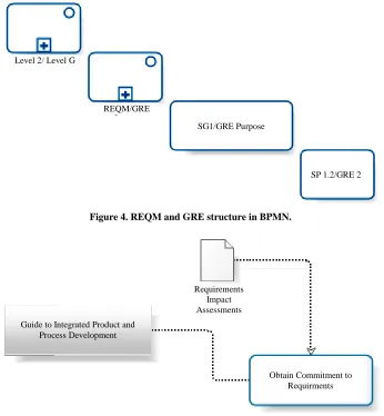
The Figure 4 presents the modeling of the components related to the GRE process of MR-MPS, and to the REQM process area of CMMI-DEV in BPMN.
The REQM and GRE are considered an Embedded Sub-Process in BPMN, corresponding to another Sub- Process that represents the Maturity Level 2 and Level G, respectively. As in Subsection 4.1 we present the first SG 1 of CMMI-DEV and the GRE Process Purpose of MR- MPS, now the components are represented by the BPMN Task component.
Both the SP 1.2 and the GRE 2 are represented by the Task notation in BPMN. These activities, as presented in Subsection 4.1, have: the Requirements Impact Assess- ments artifact, represented by the Data Object notation; the Guide to Integrated Product and Process Develop- ment procedure, represented by a Text Annotation, and the Assess the impact of requirements on existing commit- ments sub-practice. These details are presented in the mo- del of Figure 5, except for Sub-practice, since this com- ponent does not have a correspondent notation in BPMN.
This case study provides a basis to perform the analy- sis of the representativeness of SPEM and BPMN stan- dards in the context of software process modeling, pre- sented in Section 5. Immediately, it can be seen that the SP 1.2 and GRE 2 are not equally represented in both modeling standards, which allows us to draw conclusions from a more detailed analysis.
5. Analysis of Representativeness
After presenting the case study and mapping it is possi- ble to assess the representativeness of SPEM and BPMN standards. By establishing a comparison between these two standards, consider the following specific objective:
to identify which of the two standards is more suitable for process modeling software. Thus, we identified some desirable features for performing this process modeling, using as a basis the recommendations found in [13]: Expressiveness: the capability of representing the
complexity and all the assets of software processes, according to the elements of the Ontology defined in [14] and shown in Figure 1;
Reuse: the ability to promote the reuse of assets con- tained in the process model;
Management: management support of the instances of the process (planning, monitoring and control); Evolution: easiness to identify inefficient parts of the
process, thereof aiming at improvement and devel- opment;
Multilevel: ability to provide high level views of the process, as well as greatly detailed ones;
Understanding: the capability to understand the model by all involved in the process, being the ones in the organization to which the process aims or their in- tended customers, especially those who are not ex- perts in process modeling;
Organizational Integration: ability to establish inte- gration and interaction with processes in other areas of the organization, facilitating the definition of pro- cesses with overall organization objectives alignment. In order to analyze the attendance of these characteris- tics by the SPEM and BPMN standards three criteria were established, as shown in Table 2.
The Table 3 shows the analysis between SPEM and BPMN considering desired characteristics, using previ- ously set out criteria and thereof justifying, when re- quired, the choice made.
It was performed a comparative analysis to evaluate the characteristics presented in Table 3. This analysis had the following results:
SG1/GRE Purpose
SP 1.2/GRE 2 REQM/GRE
[image:8.595.126.472.86.460.2]Level 2/ Level G
Figure 4. REQM and GRE structure in BPMN.
Requirements Impact Assessments Guide to Integrated Product and
Process Development
Obtain Commitment to Requirments
Figure 5. SP 1.2 and GRE 2 representation in BPMN.
was not possible to represent the specific Subprac- tices to run the activities (Figure 5) through the BPMN notation in the Case Study. However, the SPEM notation was able to achieve that through the Step component presented in the Figure 3;
Reuse: both standards allow the reuse of the notations used to represent the process assets. In the case study, the Activity (Figure 2) and Task (Figure 4) compo- nents respectively of SPEM and BPMN were reused; Management: SPEM defines specialized notations to
process instances because it is a software process modeling standard. Both Discipline and Phase are examples of this. Nevertheless, BPMN supports this through Embedded Sub-Process (Figure 4);
Evolution: the evaluation and improvement of the process occur through the execution of it. This can help to identify weak points in the process through the analysis of the generated metrics. Regarding this, BPMN has the BPEL4WS execution language (Busi- ness Process Execution Language for Web Services).
However, SPEM is not very clear about the support to the process enactment [1];
Multilevel: both standards have appropriate notations to describe the processes in both high and low detail levels. However, the SPEM standard provides a greater number of concepts to express the multiple detail level, as evidenced with the presentation of the Process and Lifecycle notations (Table 1);
Understanding: BPMN is a standard for modeling gen-eral business processes and aims to provide an under-standable notation to all the process stake-holders. The objective of SPEM is to be a standard reference for software process modeling, using notations common to professionals in this area;
Organizational Integration: the SPEM standard fo- cuses basically on the software development area of the organization. Since BPMN standard is oriented to business processes modeling, it allows the integration of software process modeled in its notation with other business process models of an organization.
Table 2. Attendance criterias of evaluated characteristics.
Notation Significance Description
Completely Contemplated The modeling standard notations incorporate the characteristic.
Partially Contemplated The modeling standard notations incorporate partially the characteristic.
[image:9.595.83.518.188.353.2]Not Contemplated The modeling standard notations do not incorporate the characteristic.
Table 3. Analysis of SPEM and BPMN representativeness.
Characteristics SPEM BPMN Justifying
Expressiveness All the basic elements shown in the Process Ontology [14] were
identi-fied in SPEM. BPMN, on the other hand, has only some of these.
Reuse Do not apply.
Management Do not apply.
Evolution The modeling performed by using the two standards alone is not suffi-
cient to allow the process evolution.
Multilevel Do not apply.
Understanding People who are not from the software engineering area tend to have dif-
ficulty understanding the SPEM notations.
Organizational Integration
The specificity of process elements provided by SPEM hinders or even impedes this integration.
6. Final Thoughts
The objective of the comparative study presented in this paper is to bring the Software Engineering community useful information to guide the choice of a standard, from the analysis of the organizational context in which the process will be defined, including organizational cul- ture, human resources characteristics, relations between the various areas of the company. We expect this infor- mation, together with the results obtained in this work, provides software developer organizations the support to choose which technology would be more appropriate in defining and shaping their development process.
Moreover, this paper made a comparison between the elements that compose the structure of CMMI and MPS.BR. Both models, being more focused on structural part of the process, lack representativeness in the model- ing of processes with a higher degree of specification, where the SPEM has many components to represent this aspect. However, BPMN tends to be more easily under- stood and aims at the integration of organizational proc- esses, it does not have as much expressiveness in the representation of software processes adhering to these models, based upon the study case.
This evaluation of modeling standards contributed to the conception of SPIDER_ML [16], a modeling lan- guage characterized as a profile of SPEM 2.0. The choice of relying on SPEM is due to the fact that this is the OMG standard for modeling software processes, and due to the goal of SPIDER_ML to incorporate and formalize the practice of process modeling used by the software
industry using a reduced number of components when compared to the number of elements of SPEM [17,18]. This language is adopted in the tool Spider-PM in use at the SPIDER Project (acronym for Software Process Im- provement: DEvelopment and Research) [19]. This pro- ject has the major focus of presenting technological solu- tions (open source tools, frameworks, toolsets) with ap- propriated characteristics to meet the best practice de- scribed in the quality models CMMI-DEV and MR-MPS.
The SPIDER_ML extension to support flexible and semi-automated process enactment is the scope of an- other study being currently in development [20]. Based upon the definition of enactment formalism, called xSPI- DER_ML, the SPIDER_ML will fully contemplate the process evolution characteristic, in order to provide greater dissemination and understanding of the SPEM language.
7. Acknowledgements
The authors would like to thank CNPq (Conselho Na- cional de Desenvolvimento Científico e Tecnológico—Na- tional Counsel of Technological and Scientific Develop- ment), for financial support through the DTI grant of the MCT/CNPq/FNDCT No. 19/2009 announcement for the development of this work.
REFERENCES
[2] B. Curtis, M. Kellner and J. Over, “Process Modeling. Communications of ACM,” ACM, Vol. 35, No. 9, 1992, pp. 75-90.
[3] J. Lomchamp, “A Structured Conceptual and Termino- logical Framework for Software Process Engineering,” The Second International Conference on the Software Process:
Continuous Software Process Improvement, Berlin, 25-26 February 1993, pp. 41-53.
[4] W. Humphrey, “Managing the Software Process. The SEI Series in Software Engineering,” Addison-Wesley, Boston, 1989.
[5] M. Kellner and G. Hansen, “Software Process Modeling. Technical Report CMU/SEI-88-TR-009,” Carnegie Mellon University/Software Engineering Institute, Pittsburgh, 1988. [6] OMG, “Software & Systems Process Engineering Meta-Mo-
del Specification,” 2008.
http://www.omg.org/spec/SPEM/2.0/PDF
[7] OMG, “Business Process Model and Notation (BPMN),” 2011. http://www.omg.org/spec/BPMN/2.0/PDF
[8] OMG, “Object Management Group,” 1997. http://www.omg.org/
[9] S. Oliveira, A. Vasconcelos and R. Mendes, “Mapping of CMMI Guide Concepts on SPEM Notations from Software Process Definition Context,” Journal of Computer Science, Vol. 5, No. 4, 2006, pp. 83-92.
[10] SOFTEX, “MPS.BR: Guia Geral,” 2011.
http://www.softex.br/mpsbr/_guias/guias/MPS.BR_Guia_ Geral_2011.pdf
[11] SEI, “CMMI for Development,” 2010. http://www.sei.cmu.edu/reports/10tr033.pdf
[12] F. Zorzán and D. Riesco, “Transformation in QVT of Software Development Process based on SPEM to Work-flows,” Journal Latin America Transactions, IEEE, Vol.
6, No. 7, 2008, pp. 655-660.
[13] J. Pérez, “Notaciones y Lenguajes de Procesos: Una Visión Global,” Ph.D. Research Report, University of Sevilla, Sevilla, 2007.
[14] G. Guizzardi, R. Falbo and R. Guizzardi, “Grounding Soft- ware Domain Ontologies in the Unified Foundational On- tology (UFO): The Case of the ODE Software Process On- tology,” In: XI Iberoamerican Workshop on Requirements Engineering and Software Environments, Recife, 2008. [15] SOFTEX, “Guia de Implementação—Parte 11: Implementa-
ção e Avaliação do MR-MPS: 2009 em Conjunto com o CMMI-DEV v1.2,” 2011.
http://www.softex.br/mpsbr/_guias/guias/MPSBR_Guia_ de_Implementa%C3%A7%C3%A3o_Parte_11.pdf [16] SPIDER_ML, “Especificação Técnica,” 2009.
http://www.spider.ufpa.br/projetos/spider_pm/SPIDER_M L%5B1.1%5D.pdf
[17] R. Barros and S. Oliveira, “SPIDER_ML: Uma Linguagem de Modelagem de Processos de Software,” II Escola Regional de Informática, Manaus, 2010.
[18] R. Barros and S. Oliveira, “Spider-PM: Uma Ferramenta de Apoio à Modelagem de Processos de Software,” VIII En- contro Anual de Computação, Catalão, 2010.
[19] S. Oliveira, et al., “SPIDER: Uma Proposta de Solução Sis- têmica de um SUITE de Ferramentas de Software Livre de Apoio à Implementação do Modelo MPS.BR.” Revista do Programa Brasileiro da Qualidade e Produtividade em Soft- ware, 2nd Edition, 2011, pp. 103-107.
![Figure 1. Software process model derived from ODE project [14].](https://thumb-us.123doks.com/thumbv2/123dok_us/9280395.421108/3.595.133.469.85.281/figure-software-process-model-derived-ode-project.webp)