Original citation:
Strong, Austin, Thornberry, Courtney, Beattie, Shane D., Chen, Rongrong and Coles, Stuart R.. (2015) Depositing catalyst layers in polymer electrolyte membrane fuel cells : a review. Journal of Fuel Cell Science and Technology, 12 (6). 064001.
Permanent WRAP url:
http://wrap.warwick.ac.uk/75665
Copyright and reuse:
The Warwick Research Archive Portal (WRAP) makes this work by researchers of the University of Warwick available open access under the following conditions. Copyright © and all moral rights to the version of the paper presented here belong to the individual author(s) and/or other copyright owners. To the extent reasonable and practicable the material made available in WRAP has been checked for eligibility before being made available.
Copies of full items can be used for personal research or study, educational, or not-for profit purposes without prior permission or charge. Provided that the authors, title and full bibliographic details are credited, a hyperlink and/or URL is given for the original metadata page and the content is not changed in any way.
Publisher’s statement: © ASME
Article originally published by ASME in Journal of Fuel Cell Science and Technology.
Published version available: http://dx.doi.org/10.1115/1.4031961
A note on versions:
Depositing Catalyst Layers in Polymer Electrolyte Membrane Fuel Cells: A Review
Austin Strong1 , Courtney Thornberry2, Shane Beattie2, Rongrong Chen1, Stuart R. Coles2
1 Richard Lugar Center for Renewable Energy, IUPUI, Indianapolis, IN 46202-5160 2 WMG, High Value Manufacturing Catapult, University of Warwick, Coventry, UK CV4
8AL
ABSTRACT
Fuel cell technology continues to advance and offers to be a potentially promising solution to many energy needs. Of particular interest are manufacturing techniques to improve performance and decrease overall cost. For catalyst deposition on the Membrane Electrode Assembly (MEA) there are a number of techniques that have been used in the past decades. This paper aims to review many of these main techniques that have been published to show the wide variety of catalyst deposition methods.
Table Caption List
Table 1 Table 2
Description of catalyst loading levels
Catalyst loadings of main methods for MEA manufacture
Figure Captions List
Fig. 1 Schematic of electrode preparation processes for both (a) the conventional method and (b) the decal transfer method [23]
Fig. 2 The dry production technique for PEFC and DMFC MEAs [27]
Fig. 3 A visual comparison of the three main electrode manufacturing methods. [36]
Fig. 4 MEA fabrication technique utilizing slot die coating [37]
Fig. 5 Schematic of electrophoresis deposition process for preparation of MEA [84]
Fig. 6 Schematic illustration of triple phase boundary [86]
Fig. 7 Schematic of electrospray deposition of Pt/C suspensions (top) and diagram of the electrospray process from needle to substrate space (bottom) [92]
Fig. 8 Schematic of electrospinning process that produces polymer nanofibers [98]
INTRODUCTION
applications. There are several manufacturing components in a PEM fuel cell. The US Department of Energy has classified them into four main subsystems, separate from hydrogen storage:
1. The cell stack
2. The balance-of-plant 3. Power conditioning 4. System controls
Each subsystem has different manufacturing challenges. Approximately 50% of the manufacturing costs are embedded in the cell stack. This includes the Membrane Electrode Assembly (MEA) which contains the catalyst, catalyst layers, gaskets, bipolar plates, reactant manifolds (internal/external), cell stack assembly and quality assurance [8].
Costs are contributed to both material as well as manufacturing processes. One of the biggest challenges in driving down cost is in the process during which the catalyst layer is applied. Various deposition methods, like ink jet printing, vapor deposition, physical deposition, and semiconductor processing offer alternative solutions that may aid in this challenge for the manufacturing of MEAs [9]. By finding an optimal method, both the cost of process and material can be addressed in the fuel cell manufacturing process. Some challenges of manufacturing include: improving the reproducibility of the process, the speed of the process, durability of the MEA, and reduction of the overall catalyst loading [7], which will be discussed next.
The approach to reducing catalyst loading is two-fold; utilize platinum more effectively to allow for lower platinum loadings and/or to use alternative catalyst materials. A large amount of research has been focused on the catalyst materials that use less platinum. There has also been a tremendous amount of research on the methods for depositing a catalyst layer[10]–[12], however the problem still remains as to how to manufacture MEAs consistently, at low cost, and at commercial scale.
The purpose of this review is to highlight the possible array of catalyst deposition methods and trace how and why they evolved. An understanding of how deposition methods have changed to overcome challenges, and where they can go in the future will allow for greater development in the future.
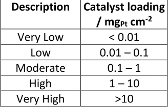
[image:3.612.224.388.611.717.2]Where appropriate, catalyst loadings have be converted to the units of mgPt cm-2 in order to obtain a realistic comparison between deposition methods. They have also been classified into groups so that the reader can gain perspective on the relative loadings in Table 1.
Table 1: Description of catalyst loading levels
Description Catalyst loading / mgPt cm-2
Very Low < 0.01 Low 0.01 – 0.1 Moderate 0.1 – 1
High 1 – 10
RESULTS AND DISCUSSION: A REVIEW OF THE LITERATURE CATALYST POWDER-BASED METHODS
This section will discuss various powder-based methods for catalyst deposition in a PEMFC MEA.
Teflon Bonded Catalyst Layers
This was one of the first methods for depositing catalyst layers and was used during the Gemini space program (1962-1966). In this method, unsupported platinum particles were mixed with PTFE particles and hot-pressed onto the electrolyte membrane. This method requires a high (4 mgPt cm-2) platinum loading, making it a non-ideal solution [13].
Brush Coating a Catalyst Coated Membrane
Brush coating a catalyst coated membrane is a technique that applies catalyst powder in an ethanol solution directly to the electrolyte membrane. This technique emerged in 1992 when the catalyst ink was painted onto the membrane and held in place by a vacuum table[14]. It has also been researched for use in Direct Ethanol Fuel Cells (DEFCs) and Direct Methanol Fuel Cells (DMFCs)[15]–[17]. The technique has also evolved to use spraying rather than hand painting [17], [18]. Hsu et al. developed a method of pretreating the Nafion film causing it to swell for catalyst deposition by spraying or blade deposition. Normally, this swelling can be problematic, but the method developed was able to address these issues. This showed good MEA performance later on, which eliminating the need for a vacuum table to hold the membrane in place during catalyst deposition [18]. While the processes vary significantly, applying catalyst mixtures directly on the membrane became the foundation for many methods of depositing catalyst layers.
Brush Coating a Decal to Transfer
Figure 1: Schematic of electrode preparation processes for both (a) the conventional method and (b) the decal transfer method [23]
Screen Printing a Catalyst Slurry
Screen printing is first reported in the literature in 1995, when Wilson et al.
performing better than a membrane that was screen printed without gasket material [26]. In 2007, Rajalakshmi et al. combined the screen printing method with the decal transfer method, printing onto a decal transfer substrate[27]. The distribution of platinum was also analysed and it was found to be uniform with interfacial resistance decreasing by 50% using this combined method. The reduced resistance helps maintain higher current while the cell is being discharged [27].
Dry Powder
[image:6.612.108.485.356.539.2]The dry powder, cold rolling process was first created by the DLR group in Stuttgart. In 1995 they were able to create MEAs using a dry powder mixture of Nafion, PTFE, and platinum-coated carbon black. A cold rolling process was used to laminate gas diffusion electrodes on both sides of a Nafion membrane [28]. In 1998 the process was automated by making it a gravity-fed system and perfecting the rolling process [29]. Another report showed that the Nafion powder could be removed, enabling the process to be fully automated using a slot nozzle and nitrogen gas to blow the mixture onto the gas diffusion membrane or directly onto the Nafion membrane [30]. That work also described the creation of a hot rolling process to make the MEA. By 2002 the process and MEA components were optimized so that the electrochemical results from MEAs produced by this process were promising[31]. A technique for dry production is shown in Figure 2.
Figure 2- The dry production technique for PEFC and DMFC MEAs[30]
Doctor Blade
In 2002, Saab et al. were able to use the doctor blade coating method on a membrane that was in the protonated form, thus eliminating the ion exchange steps in the process or producing a MEA [32]. The addition of glycerol in the ink to improve printability was then studied. It was found that glycerol caused the ionic resistivity of the catalyst layer to be reduced by 75%, while only increasing electrical resistivity by 30% [32]. In 2003, Bender et al. combined the doctor blade method with the decal transfer method, printing on to a substrate then hot pressing it onto a Nafion membrane [33]. This study found acceptable reproducibility in terms of uniform coating
Rolled MEA
thickness. Unfortunately, this study also revealed problems with mass reproducibility (applying the same amount of catalyst) that seemed to be linked with ink evaporation and component settling. It was found that by using a water-based catalyst ink, and a Kapton substrate, a reduction in the variation in platinum loading was possible to ±5%. The authors present the fact that while this particular process is useful for creating MEAs in a laboratory setting, it may not have industrial application due to the time involved in each step [33].
Inkjet Printing
In 2007, Towne et al. detailed the process of using inkjet printing to produce a MEA, including the detailing of the general requirements of an ink solution used for printing with this method [34]. The process was demonstrated by printing a catalyst solution directly onto a Nafion membrane. The surface was examined to verify uniform distribution. The authors also investigated the secondary processes such as water soaking and hot pressing. By printing a MEA with a loading of 0.2 mgPt cm-2, a power density of 154 mW cm−2 was achieved. A comparable commercial MEA loaded with 0.3 mgPt cm-2 was shown to produce a power density of 167 mWcm−2 [34]. Another study in 2007, Taylor et al., used inkjet printing to print catalyst layers onto carbon cloth using a loading of 0.51 mgPt cm-2 [35]. This showed little difference in performance versus hand painted MEAs. However, under ultra-low platinum loading of 0.021 mgPt cm-2, the printed MEA produced 17.6 W mg-1Pt. The ability of inkjet printing to create a graded structure of varying catalyst/Nafion ratios was also demonstrated by Taylor et al. [35]. In 2009, Saha et al. examined the morphology of a MEA printed onto Nafion and found it to be more uniform at lower platinum loading. Further durability testing found no significant decrease in performance after 18 hours of discharging at 300 mA cm-2 [36].
In 2012, Malevich et al. investigated the effect of printing geometrically patterned catalyst layers onto Nafion membranes for MEAs [37]. It was discovered that the patterns had a profound effect both on electrochemically active surface area, and in the polarizations due to activation and mass transport [37]. Also in 2012, Yazdanpour et al. investigated the effects of the hot-press assembly parameters (temperature, pressure, and time). They found that cell performance decreased with pressure, temperature, and time. They predicted an optimum hot press process of 800 psi at 100 oC for 3 minutes. Using these conditions, an MEA was prepared by printing onto Nafion
and was found to have higher electrochemically active surface area than a MEA prepared using the decal transfer method with identical platinum loading [38].
Scrape Method
Figure 3: A visual comparison of the three main electrode manufacturing methods. [39]
Slot Die Coating
Ding et al.(2012) investigated using a slot die to deposit a liquid layer onto gas diffusion layers. During single cell testing, the MEAs were found to have similar results as traditionally produced MEAs. The authors also identified several problems with this production technique and worked to mitigate them. Through experiments, the authors found that using a microporous layer and forced convection to reduce ink penetration. Additionally, using a pressing operation improves uniform coating thickness [40]. Figure 4 shows the MEA fabrication technique utilizing slot die coating.
[image:8.612.237.408.472.685.2]VAPOUR BASED METHODS Plasma Sputtering
Platinum sputtering was used as early as 1969 with respect to electrochemical cells [41]. However, there is no record that platinum was sputtered onto fuel cell electrodes until 1987. At this time, a layer of platinum was sputtered onto Teflon-bound electrodes. Half-cell tests were performed and this method was found to be very promising, offering only a slightly decreased performance versus a conventional electrode with twice the platinum loading. This was attributed to superior performance of the oxygen reduction reaction (ORR) [42].
In 1988, Ticianelli et al. performed a thorough investigation to characterize how sputtered electrodes performed in a cell. They found that by sputtering a coating of platinum onto the surface of low (0.4 mgPt cm-2) loaded electrodes, current densities could be produced that rivaled conventional cells.The authors found that at a current density of 1 A cm-2, the sputtered electrodes produced twice the power of conventional electrodes. The sputtered electrodes were also found to be stable over time, at several different discharging current densities [43]. In 1993, Mukerjee et al. performed an in-depth investigation of how a sputtered catalyst layer improved the kinetics of oxygen reduction. This study revealed better platinum exposure, and lower activation losses. These led to significant improvements in current density [44].
DC Plasma Sputtering
In 1997, Hirano et al. made a significant step when they investigated sputtering platinum onto an electrode that had no catalyst content. It was illustrated that sputtered electrodes with platinum loadings as low as 0.1 mgPt cm-2 could still produce high current densities and produced a maximum power density of 714 mW cm-2. However, the performance was still slightly less than a conventional electrode with 0.4 mgPt cm-2. This was attributed to higher ohmic losses in the sputtered electrodes [45].
The process evolved in 1999 when Cha and Lee sputtered platinum directly onto a Nafion membrane, Both DC and RF sputtering techniques were used, with appropriate power and pressure to each system. The samples studied in the work were not differentiated by specific sputtering technique in the result, indicating that the technique was considered irrelevant to subsequent sample measurements. Sputtering directly onto the membrane created with a platinum loading of 0.04 mgPt cm-2 generated a specific power of nearly 6 W mg-1Pt. A conventional electrode with a platinum loading of 0.4 mgPt cm-2 generates a specific power of ~ 1 W mg-1Pt. Applying an ink solution of Nafion and carbon between layers of sputtered platinum was also found this to improve performance [46].
sputtering layers of ruthenium between layers of platinum to improve the tolerance of carbon monoxide. The separation of ruthenium layers was found to double the tolerance of carbon monoxide compared to traditional platinum-Ruthenium alloys [48].
In 2002, major progress was made when sputtering was shown to shown to have tremendous potential for lowering platinum loadings. In this instance, a sputtered cell produced 60% of the power density of a conventional cell, with much lower catalyst loadings. A conventional cell, defined as an ink-based method of fabrication, contained 10 times the amount of platinum catalyst that was in the sputtered cell. Sputtering was also shown to be durable in several qualitative tests of the surface, particularly in longer term performance testing which did not show any performance degradation [49].
Very High Frequency (VHF) Sputtering
In 2004, the process evolved when Brault et al. used VHF inductive sputtering to deposit platinum onto gas diffusion layers for the first time. This was done to obtain a better understanding of the deposition process, specifically to understand catalyst penetration in the electrodes. Platinum was deposited at a loading of 0.08 mgPt cm-2 to a depth of 2 µm, resulting in a specific power of 5 W mg-1Pt [50].
Radio Frequency (RF) Sputtering
In 2005, Gruber et al. demonstrated the ability to obtain ultra-low platinum loadings, depositing 5 µgPt cm-2. This loading level in both anode and cathode achieved a power density of 124 mW cm-2. The authors also demonstrated that power density could be increased by sputtering chromium or vapor depositing palladium onto a 25 nm platinum layer [51]. In 2007, applying thin film layers between the electrode and the layer of platinum was attempted. It was found that a sub-layer of chromium, palladium, or silicon-based polymers helps to distribute the platinum more uniformly, and further increase power density. The authors also investigated the effect of oxygen plasma treatment of commercial electrodes and found improved power densities by exposing increased catalyst sites[52].
Transformer Coupled RF Sputtering
A variation of RF sputtering process is transformer coupled RF sputtering. It is unclear when this process evolved and little literature was found regarding the origin and history of transformer coupled RF sputtering. However, the method is worth noting due to promising recent results. In 2011, a transformer coupled RF sputtering method was used to deposit a pure palladium anodic catalyst layer and a 10% platinum / palladium catalyst layer for a catalyst electrode. With total loadings of 20 µgPd cm-2 and 1 µgPt cm-2, a specific power of 12.5 kW g-1Pd and 250 kW g-1Pt was achieved [56].
Magnetron Sputtering
In 2006, Wan et al. demonstrated the use of magnetron sputtering for depositing the catalyst layer. Magnetron sputtering uses a magnetic field to control the plasma and focus it onto the target, in this case it is unclear if the plasma was generated by DC or RF excitation; it is known that the pressure of the deposition occurred on the order of 10-3 Torr with a target current of 0.25 A. An advantage of this method is that it allows for shorter sputtering times, which ranged from 30 to 470 seconds. In their study, the authors investigated the effect of bias voltage, pressure, and sputtering time on cell performance and found a direct correlation to catalyst porosity, thickness and loading. They also demonstrated the ability to deposit multiple layers of platinum using this method [57].
In 2008, Yoo et al. further investigated the effect of sputtering pressure on fuel cell performance. They found that high pressure of approximately 200 mTorr produced catalyst layers with significantly higher electrochemically active surface area, leading to power density of 420 mW cm-2 and a specific power of 10.5 W mg-1 [58]. Also in 2008, Kim et al. expanded the three dimensional reaction zone by sputtering platinum onto a layer of Vulcan XC-72 and carbon nanotubes. The electrochemically active surface area was increased, and a catalyst layer with this structure outperformed a screen-printed electrode with a platinum loading ten times higher. This was attributed to high mass activity and good mass transport characteristics[59].
In 2009, Cavarroc et al. used magnetron sputtering to deposit an ultra-low loading of 10 µg cm-2 with carbon particles and achieved a power density of 400 mW/cm2. This corresponded to a specific power of 20 kW g-1Pt, which was reported to be the highest specific power at the time [60]. In 2010, Natarajan and Hamelin evolved the layering technique to further expand the reaction zone. They sputtered differing platinum loadings on different levels, with layers of Nafion and carbon nanotubes between the platinum layers. A structure with three layers of platinum containing a total loading of 0.5 mgPt cm-2 with layers of carbon nanotubes and 29% Nafion was found to be optimal [61].
Decal Sputtering
was found to be suitable, particularly for micro fuel cells because of suitable horizontal conductivity in the catalyst layer [62].
Helicon RF Sputtering
In 2007, Caillard and coworkers investigated helicon plasma sputtering to apply catalyst layers. Carbon nanofibers were grown and platinum was deposited onto the fibers. This method was shown to allow for platinum utilization four times higher than conventional electrodes with higher platinum loading [63]. In 2008, a study was performed on different carbon support layers such as Vulcan XC-72, carbon nanofibers, and the combination thereof, for the platinum layer. They also demonstrated that electrodes prepared by these methods were suitable for both the anode and cathode [64]. In 2009, significant progress was made by optimizing plasma parameters as well as Nafion and platinum content. By optimizing these parameters, they were able to load electrodes with 5 µg of platinum and obtain an anodic specific power of 85 kW g-1Pt, which was 100 times higher than a commercial anode with 0.5 mgPt cm-2. The cathodic specific power at the same ultra-low platinum loading was found to be 22.5 kW g-1Pt, which was approximately 26.5 times higher than the commercial electrode [65].
Ion Beam in Catalyst Deposition Ion Beam Assisted Deposition
It is unclear when ion beams were first used for depositing coatings, however the method is reported in the literature for depositing fuel cell catalyst layers as early as 1983 [66]
Dual Ion Beam Bombardment
Dual ion beam bombardment was used for depositing fuel cell catalyst layers in 2005. It was deemed a useful method due to its ability to use one beam to roughen the surface of the substrate and a second beam to deposit catalyst particles [67]. In 2005, it was used to deposit platinum onto gas diffusion media and performance was shown to be similar to a commercial electrode [68]. In 2006, this method was employed to deposit layers of cobalt and chromium beneath the platinum. Using dual metals led to increased performance and allowed for less platinum loading on the electrodes [69]. Also in 2006, a detailed analysis using this method was performed, measuring results for various ultra-low platinum loadings. The kinetics of the oxygen reduction reaction were also studied with respect to this method of depositing the catalyst layer and it was found that a patterning method of deposition helped to mitigate transport losses in the cell and thus improving performance [70]. In 2009, further investigation was performed on catalyst layers that were deposited using this method. Degradation analysis was performed using a radical attack technique, and the dual ion beam deposited layer was found to have better durability than a commercial electrode [67].
Pulsed Laser Deposition
ELECTRICAL PROCESSES Electrodeposition
Electrodeposition of platinum from chloroplatinic acid was first performed in 1894. Since then there were a number of investigations of the process and variables including substrate treatments, different acid electrolytes, and other chemicals mixed with the electrolyte. There were also studies performed that examined the appearance and growth of the platinum deposits [72]. In 1986, Itaya et al. applied a film of Nafion to glassy carbon electrodes, and performed platinum electrodeposition. They were able to deposit platinum on the surface of the electrode and through the layer of Nafion [73]. In 1992, Taylor et al. used a commercial plating bath to deposit platinum on the surface of a carbon electrode that was coated with Nafion. This method requires regions where both electrical and ionic conductivity are possible, effectively “targeting” the three-phase boundary required for the catalyst to be used [74]. In 1994, Verbrugge proposed a modified method and was able use dilute platinum salt solutions to selectively deposit platinum on the surface of a carbon electrode that was coated with Nafion which was so successful it became the standard method for electrodeposition of platinum salts [75].
Ion exchange electrodeposition
In 2001, Thompson et al. suggested a method to exchange platinum cations with Nafion in solution. The solution was then applied to an electrode and electroreduced in sulfuric acid. This deposited the platinum very near to the surface of the electrode, and also changed the Nafion back to proton form [76].
Pulsed electrodeposition
In 1998, Choi et al. compared pulse electrodeposition with DC electrodeposition and found it favorable because the size of platinum particles could be controlled by use of the electrical duty cycle and current density. They were able to deposit platinum particles smaller than 50 nm. They found that brushing the surface of the electrode with carbon and PTFE was favorable because it provided more sites for nucleation. The authors also investigated the parameters of the pulse electrodeposition process including duty cycle (on time and off time), and current density. After optimization of the process, MEAs prepared by pulse electrodeposition were found to perform better than those prepared by DC electrodeposition [77]. Kim and Papov used a similar method and were able to limit platinum particle size to less than 5 nm whilst using a 75% platinum on carbon source, and the catalyst layer catalyst layer was only 50 µm thick (Kim & Popov, 2004). In the same year, the authors performed a detailed analysis of their new pulse electrodeposition method versus direct current electrodeposition and found the performance to be favorable. They also performed further investigation of the pulse electrodeposition parameters [79].
In 2007, Ayyadurai et al. tested the effect of hydrophilic agents on the pulse electrodeposition process. The authors adding wetting agents to the electrodeposition mixture and found this to increase the rate of platinum deposition, while maintaining uniformity of deposition and controlling particle growth. They were also able to limit the depth of deposition to less than 2 µm [81].
In 2008, Rajalakshmi and Dhathathreyan further investigated the various parameters of the pulse electrodeposition process, including duty cycle, Nafion content, and current density. By optimizing these factors, the ohmic resistance was lowered significantly to 0.00076 mΩ cm-2 [82].
In 2009, Martin et al. characterized the depositions of platinum nanoclusters using physical and chemical methods. They found that the depth of deposited platinum was limited by the diffusion of the precursor. They illustrated the ability to use electrodeposition to prepare electrodes with platinum loading less than 0.05 mgPt cm-2 [83].
Current Modulated Electrodeposition
A change to the pulse electrodeposition method was proposed by Wei et al. in 2007. Seeing problems with current rise and fall during normal pulse electrodeposition, the authors used current modulation to control the duty cycle and peak current density. While this method did show up to 69% platinum utilization, there were still drawbacks including hydrogen evolution and large particle sizes [84].
Ultrasonic Electrodeposition
The electrodeposition method evolved again in 2008 when Pollet applied ultrasound to a pulsed galvanostatic electrodeposition bath. In this study, an MEA with a catalyst layer prepared by this method was shown to have improved performance over silent pulse galvanostatic electrodeposition. It is thought that this method acts as a “reducing agent” to help form particles with better catalytic properties [85], [86].
Electrophoresis
In 2004, Moriwaka et al. proposed the use of electrophoresis to deposit catalyst layers. This method took advantage of surface charges on particles, and was useful because it could be applied to many different membrane materials. It was also advantageous because it eliminated the hot pressing step that is common to many MEA fabrication methods. After optimizing the electrophoresis process for their membrane and catalyst mixture, they examined the catalyst layer. They found more uniform deposition of particles, and a thinner catalyst layer than an MEA prepared by the decal method. It was also found to utilize 56% of the deposited platinum, and to perform better in single cell discharge testing than a hot pressed MEA [87]. By 2006, Munakata
Electrophoretic electrodeposition
[image:15.612.104.499.380.634.2]In 2011, an electrophoresis deposition method was proposed by Yu et al. This method is a combination of electrophoresis and electrodeposition. It uses an electric field to control the size of the platinum particles deposited by electrodeposition. They succeeded in depositing platinum nanoparticles onto the electrode, and controlling the size to 3-4 nm. They also found that using a 25% duty cycle for 10 minutes led to a peak specific current of 440 mA mgPt-1 [90]. In 2013, Adilbish et al. further investigated this technique. They varied the duty cycle and found that a 25% duty cycle (on a 1 minute scale) yielded the best surface morphology of platinum clusters. After optimizing the duty cycle, they investigated the effect of time on the deposition of platinum on the electrode. They also analyzed the effect of deposition time on electrochemically active surface area. They found that with time, the hydrogen oxidation activity increases, but the electrochemically active surface area decreases after ten minutes. While this technique is very new, they were able to achieve a specific power density of 3.88 W mgPt-1 [91]. Also in 2013, Felix et al. further optimized the electrophoresis process by investigating Nafion content, pH level of the solution, and field strength. Single-cell testing demonstrated poor performance, but this was attributed to Nafion not being a suitable ionomer for high temperature PEMFCs [92]. Figures 5 and 6 show the schematic of the electrophoresis deposition process for the MEA and an illustration of the triple phase boundary from this technique, respectively.
Figure 6: Schematic illustration of triple phase boundary [89]
Electrospray
In 2005, Baturina and Wnek evaluated the use of electrospraying for use in PEFCs. They sprayed the catalyst directly onto the electrolyte membrane, and were able to obtain a current density of 1 A cm-2 during single cell testing [93]. In the same year, Benitez et al. used electrospraying to apply a catalyst layer to the gas diffusion layer. They then compared the electrospray technique with traditional spraying and platinum impregnation methods, as well as a commercial MEA. The electrosprayed MEA was found to have the highest current values at identical platinum loadings. The MEAs were examined using surface methods and found to have more uniform platinum distribution, which led to the higher results [94].
In 2007, Chaparro et al. then investigated the effect of a high temperature solvent (butylacetate, ethanol, and glycerol) instead of isopropanol on MEA performance. This was done because using isopropanol appeared to cause changes to the Nafion ionomers in the electrospray solution because it evaporates at a low temperature. Using a high temperature solvent they were able to increase mass specific area to 101 m2 g-1. At a cathode loading of 0.3 mgPt cm-2, they showed slightly better performance in low current density than a commercial MEA with a cathode loading of 0.5 mgPt cm-2. However, the electrosprayed MEAs had higher mass transport losses in high current density. The stability of an electrosprayed MEA was also investigated and found to have a decay rate of 7 microvolts per hour over 600 hours, at a current demand of 500 mA cm-2 [95].
In 2010, Martin et al. optimized the control parameters of the electrospray process, the Nafion content of the ink, and the hot press process after spraying. This led to a very developed fractal structure and high performance [96]. The same year, they also optimized the operating conditions for cells using an MEA prepared with this technique. With a platinum loading of 0.012 mgPt cm-2 on the cathode, they were able to attain a cathode specific power of 20 kW g-1Pt [97].
Figure 7: Schematic of electrospray deposition of Pt/C suspensions (top) and diagram of the electrospray process from needle to substrate space (bottom) [95]
Electrospinning
Zhang et al. started investigating the use of electrospinning to deposit a mixture of catalyst, Nafion, and poly(acrylic acid) onto aluminum foil. The fibers were then annealed and hot pressed it to a Nafion membrane. During single cell testing, the electrospun MEA generated 44% more power at high humidity conditions than a decal MEA of identical platinum loading. Under low humidity conditions, this difference was much greater, with the electrospun MEA generating 129% more power than the decal MEA [99].
The same year, Zhang and Pintauro did more diagnostic testing on MEAs produced by electrospinning the catalyst mixture. They found that the morphology remained intact after hot pressing, and also quantified the electrochemically active surface area of their MEA at 114 m2 g-1Pt, nearly twice that of a MEA produced by the decal transfer method with the same platinum loading. They also reported a mass specific activity of 0.23 A mg-1Pt at a potential of 0.9 V, which was one of the highest in literature. This also matched a commercially nanostructured material. [100].
In 2013, Sighter et al. investigated the use of electrospinning to produce a platinum nanofiber mat that was transferred to a Nafion membrane by the decal transfer method. They found that at a platinum loading of 0.1 mgPt cm-2 the electrospun MEA had 30% higher current density and 62% higher electrochemical surface area as compared to an MEA that was prepared by ultrasonic spraying with the same platinum
loading [101]. Also in 2013, Brodt et al. found that at a potential of 0.65 V, an electrospun anode at 0.1 mgPt cm-2 and an electrospun cathode at 0.065 mgPt cm-2 had a 29% higher power density than a decal MEA with anode loading of 0.4 mgPt cm-2 and a cathode loading of 0.104 mgPt cm-2. Additionally, they found that with electrospun anode loading of 0.059 mgPt cm-2 and a cathode loading of 0.055 mgPt cm-2, they could produce a power density of 906 mW cm-2, using 2000 sccm of humidified air, at a temperature of 80 ˚C [102]. Figure 8 shows the schematic of the electrospinning process that produces polymer nanofibers.
Figure 8: Schematic of electrospinning process that produces polymer nanofibers [101]
ULTRASONIC SPRAY
It is unclear when the ultrasonic spray method was first used for depositing fuel cell catalyst layers. It appears in literature in 2010 [103], although this instance reveals that the ultrasonic spray method has been commercialized by Sonotek since 1975. A patent application filed in 2009 and published in 2010 (2010/0078496) lists the use of ultrasonic spray to deposit catalyst layers for fuel cells. In 2011, this method was used by Millington et al. to deposit a catalyst layer onto gas diffusion layers. In that study, the authors compared multiple gas diffusion electrodes that were prepared by hand painting and ultrasonic spraying. The study found performance was similar at high platinum loading, but at lower platinum loading ultrasonic spray was preferential. This was attributed to the ultrasound energy preventing clogging and agglomeration of particles. A peak platinum utilization of 10.9 W mg-1Pt was obtained at a loading of 50 µgPt cm-2 [104]. The same year, Huang et al. used the same method to apply a catalyst layer to Nafion membrane. The authors tuned the parameters of the spray process and were able to obtain approximately 89% platinum utilization. It was also noted during testing that the cells exhibited no limiting current behavior at very high current densities, indicating exceptional mass transport properties [105]. In 2012, Huang et al.
NANOSTRUCTURED CATALYST LAYERS
Nanostructuring of catalyst layers has gained increasing importance as research drives platinum loadings lower and lower. One of the earliest examples of this technique was proposed by Middelmen. In 2002 he proposed a “self-assembly” method of nano-structuring. He theorized an ideal structure of platinum coated supports, perpendicular to the electrolyte surface. This would allow protons to conduct freely through perpendicular pores to the electrolyte membrane, and it would allow a direct path for electrons to conduct to the conductive gas diffusion media. He was able to manipulate materials, reaction variables, and use electric field to create this morphology [107].
Since Middelmen’s work, a number of nanostructures have been designed by researchers. Many of these structures were new at the time and it is difficult to trace how the nanostructuring approach has evolved through time. In lieu of a history of the nanostructuring method a list of examples is offered. This list is not intended to be all-inclusive; it is merely a sample of what types of nanostructures have been created for use in the catalyst layer of fuel cells. Readers who are interested in these methods are encouraged to research literature in this area.
Chemical reduction of platinum onto carbon nanotubes [108].
Chemical reduction of platinum onto a mixture of carbon nanotubes and carbon fibers to be assembled using a layer-by-layer method [109].
Chemical reduction of platinum to in an urchin-like structure [110].
Chemical reduction of platinum into nanoclusters [111]
Platinum nanowires have been grown on the surface of platinum gauze [112], carbon nanospheres [113], onto the surface of gas diffusion layers [114], or used as seeds for nanoflowers [115].
Specific crystal structures have been created [116]
CONCLUSIONS
In total, five main processes for producing the catalyst layer have been presented:
Catalyst powder-based methods (8 processes listed)
Vapour based methods (9 processes listed)
Electrical processes (8 processes listed)
Ultrasonic spray
Nanostructured catalyst layers
no literature that gave any indication of the loading for the nanostructured catalyst layer method. Table 2 indicates the catalyst loadings for the methods that had published information about their loadings.
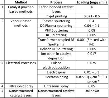
Table 2: Catalyst Loadings of Main Methods for MEA Manufacture
Method Process Loading (mgPt cm-2)
1 Catalyst powder-based methods
Teflon bonded catalyst layers
4
Inkjet printing 0.021 - 0.5
2 Vapour based methods
Plasma sputtering 0.4 DC Plasma sputtering 0.04 – 0.1
VHF Sputtering 0.08
RF Sputtering 0.005
Transformer coupled RF Sputtering
0.001 (*mixed with Pd)
Helicon RF Sputtering 0.005 Ion beam in catalyst
deposition
0.017
3 Electrical Processes Pulsed electrodeposition
0.025
Electrospray 0.01 – 0.3 Electrospinning 0.877 µgPt cm-2 – 0.1
mgPt cm-2
4 Ultrasonic spray Ultrasonic spray 0.05
5 Nanostructured catalyst layers
Nanostructured catalyst layers
Unknown
In addition to lowering the catalyst loading, which will help to significant reduce costs in any scale up context, some of these methods show great promise in durability and performance and offer great potential for the future of fuel cell manufacturing.
ACKNOWLEDGMENT
The authors would like to acknowledge the WMG High Value Manufacturing Catapult at the University of Warwick, Coventry, UK and the Richard G. Lugar Center for Renewable Energy at Indiana University Purdue University, Indianapolis, USA.
FUNDING
REFERENCES
[1] S. Giddey, S. P. S. Badwal, A. Kulkarni, and C. Munnings, “A comprehensive review of direct carbon fuel cell technology,” Prog. Energy Combust. Sci., vol. 38, no. 3, pp. 360–399, 2012.
[2] Y. Wang, K. S. Chen, J. Mishler, S. C. Cho, and X. C. Adroher, “A review of polymer electrolyte membrane fuel cells: Technology, applications, and needs on fundamental research,” Appl. Energy, vol. 88, no. 4, pp. 981– 1007, Apr. 2011.
[3] M. Z. F. Kamarudin, S. K. Kamarudin, M. S. Masdar, and W. R. W. Daud, “Review: Direct ethanol fuel cells,”
Int. J. Hydrogen Energy, pp. 1–16, Sep. 2012.
[4] a. Kirubakaran, S. Jain, and R. K. Nema, “A review on fuel cell technologies and power electronic interface,”
Renew. Sustain. Energy Rev., vol. 13, no. 9, pp. 2430–2440, Dec. 2009.
[5] J. Wing, “Why Fuel Cells for Telecoms Backup is a Good Call,” Fuel Cell Today, Jun-2013.
[6] J. W. Kim, “Recent Achievements in Hydrogen and Fuel Cells in Korea,” in International Hydrogen Energy Development Forum, 2013.
[7] “Pathways to Commercial Success : Technologies and Products Supported by the Fuel Cell Technologies Program,” 2012.
[8] B. D. James and A. B. Spisak, “Mass Production Cost Estimation of Direct H2 PEM Fuel Cell Systems for Transportation Applications: 2012 Update,” 2012.
[9] US Dept of Energy and National InstituteOf Standards, “Manufacturing for the Hydrogen Economy Manufacturing Research & Development of PEM Fuel Cell Systems for Transportation Applications,” 2005.
[10] V. Mehta and J. S. Cooper, “Review and analysis of PEM fuel cell design and manufacturing,” J. Power Sources, vol. 114, no. 1, pp. 32–53, Feb. 2003.
[11] S. Litster and G. McLean, “PEM fuel cell electrodes,” J. Power Sources, vol. 130, no. 1–2, pp. 61–76, May 2004.
[12] J.-H. Wee, K.-Y. Lee, and S. H. Kim, “Fabrication methods for low-Pt-loading electrocatalysts in proton exchange membrane fuel cell systems,” J. Power Sources, vol. 165, no. 2, pp. 667–677, Mar. 2007.
[13] S. Srinivasan, “Advances in solid polymer electrolyte fuel cell technology with low platinum loading electrodes.,” J. Power Sources, vol. 22, no. 3, pp. 359–375, 1988.
[14] M. S. Wilson, “High Performance Catalyzed Membranes of Ultra-low Pt Loadings for Polymer Electrolyte Fuel Cells,” J. Electrochem. Soc., vol. 139, no. 2, p. L28, 1992.
[15] S. Q. Song, Z. X. Liang, W. J. Zhou, G. Q. Sun, Q. Xin, V. Stergiopoulos, and P. Tsiakaras, “Direct methanol fuel cells: The effect of electrode fabrication procedure on MEAs structural properties and cell performance,” J. Power Sources, vol. 145, no. 2, pp. 495–501, Aug. 2005.
[17] J. Zhang, G. Yin, Z. Wang, and Y. Shao, “Effects of MEA preparation on the performance of a direct methanol fuel cell,” J. Power Sources, vol. 160, no. 2, pp. 1035–1040, Oct. 2006.
[18] C. Hsu, “An innovative process for PEMFC electrodes using the expansion of Nafion film,” J. Power Sources, vol. 115, no. 2, pp. 268–273, Apr. 2003.
[19] M. S. Wilson and S. Gottesfeld, “Thin-film catalyst layers for polymer electrolyte fuel cell electrodes,” J. Appl. Electrochem., vol. 22, pp. 1–7, 1992.
[20] M. S. Wilson, J. A. Valerio, and S. Gottesfeld, “Low Platinum Loading Electrodes for Polymer Electrolyte Fuel Cells Fabricated using Thermoplastic Ionomers,” Electrochim. Acta, vol. 40, no. 3, pp. 355–363, 1995.
[21] J. H. Cho, J. M. Kim, J. Prabhuram, S. Y. Hwang, D. J. Ahn, H. Y. Ha, and S.-K. Kim, “Fabrication and evaluation of membrane electrode assemblies by low-temperature decal methods for direct methanol fuel cells,” J. Power Sources, vol. 187, no. 2, pp. 378–386, Feb. 2009.
[22] K.-H. Kim, K.-Y. Lee, H.-J. Kim, E. Cho, S.-Y. Lee, T.-H. Lim, S. P. Yoon, I. C. Hwang, and J. H. Jang, “The effects of Nafion® ionomer content in PEMFC MEAs prepared by a catalyst-coated membrane (CCM) spraying method,” Int. J. Hydrogen Energy, vol. 35, no. 5, pp. 2119–2126, Mar. 2010.
[23] S. Song, G. Wang, W. Zhou, X. Zhao, G. Sun, Q. Xin, S. Kontou, and P. Tsiakaras, “The effect of the MEA preparation procedure on both ethanol crossover and DEFC performance,” J. Power Sources, vol. 140, no. 1, pp. 103–110, Jan. 2005.
[24] C. S. Kim, Y. G. Chun, D. H. Peck, and D. R. Shin, “A Novel Process to Fabricate Membrane Electrode Assemblies for Proton Exchange Membrane Fuel Cells,” Int. J. Hydrogen Energy, vol. 23, no. 11, pp. 1045– 1048, 1998.
[25] Y.-G. Chun, C.-S. Kim, D.-H. Peck, and D.-R. Shin, “Performance of a polymer electrolyte membrane fuel cell with thin film catalyst electrodes,” J. Power Sources, vol. 71, no. 1–2, pp. 174–178, Mar. 1998.
[26] J. W. Ihm, H. Ryu, J. S. Bae, W. K. Choo, and D. K. Choi, “High performance of electrode with low Pt loading prepared by simplified direct screen printing process in PEM fuel cells,” J. Mater. Sci., vol. 39, no. 14, pp. 4647–4649, Jul. 2004.
[27] N. Rajalakshmi and K. S. Dhathathreyan, “Catalyst layer in PEMFC electrodes—Fabrication, characterisation and analysis,” Chem. Eng. J., vol. 129, no. 1–3, pp. 31–40, May 2007.
[28] K. Bolwin, E. Giilzow, D. Bevers, and W. Schnumberger, “Preparation of porous electrodes and laminated electrode- membrane structures for polymer electrolyte fuel cells ( PEFC ),” Solid State Ionics, vol. 2738, no. 95, pp. 324–330, 1995.
[29] D. Bevers, N. Wagner, and M. Von Bradke, “Innovative Production Procedure for Low Cost PEFC Electrodes and Electrode/Membrane Structures,” Int. J. Hydrogen Energy, vol. 23, no. 1, pp. 57–63, 1998.
[30] E. Gülzow, M. Schulze, N. Wagner, T. Kaz, R. Reissner, G. Steinhilber, and a Schneider, “Dry layer preparation and characterisation of polymer electrolyte fuel cell components,” J. Power Sources, vol. 86, no. 1–2, pp. 352–362, Mar. 2000.
[32] A. P. Saab, F. H. Garzon, and T. a. Zawodzinski, “Determination of Ionic and Electronic Resistivities in Carbon/Polyelectrolyte Fuel-Cell Composite Electrodes,” J. Electrochem. Soc., vol. 149, no. 12, p. A1541, 2002.
[33] G. Bender, T. a Zawodzinski, and A. P. Saab, “Fabrication of high precision PEFC membrane electrode assemblies,” J. Power Sources, vol. 124, no. 1, pp. 114–117, Oct. 2003.
[34] S. Towne, V. Viswanathan, J. Holbery, and P. Rieke, “Fabrication of polymer electrolyte membrane fuel cell MEAs utilizing inkjet print technology,” J. Power Sources, vol. 171, no. 2, pp. 575–584, Sep. 2007.
[35] A. D. Taylor, E. Y. Kim, V. P. Humes, J. Kizuka, and L. T. Thompson, “Inkjet printing of carbon supported platinum 3-D catalyst layers for use in fuel cells,” J. Power Sources, vol. 171, no. 1, pp. 101–106, Sep. 2007.
[36] M. S. Saha, D. K. Paul, D. Malevich, B. A. Peppley, and K. Karan, “Preparation of Ultra-Thin Catalyst Layers by Piezo-electric Printer for PEMFCs Applications,” ECS Trans., vol. 25, no. 1, pp. 2049–2059, 2009.
[37] D. Malevich, M. S. Saha, E. Halliop, B. A. Peppley, J. G. Pharoah, and K. Karan, “Performance Characteristics of PEFCs with Patterned Electrodes Prepared by Piezo-electric Printing,” ECS Trans., vol. 50, no. 2, pp. 423–427, 2012.
[38] M. Yazdanpour, A. Esmaeilifar, and Soosan Rowshanzamir, “Effects of hot pressing conditions on the performance of Nafion membranes coated by ink-jet printing of Pt/MWCNTs electrocatalyst for PEMFCs,”
Int. J. Hydrogen Energy, vol. 37, pp. 11290–11298, 2012.
[39] S. D. Wu, C. P. Chou, R. G. Peng, C. H. Lee, and Y. Z. Wang, “A novel scrape-applied method for the
manufacture of the membrane–electrode assembly of the fuel–cell system,” Acta Mech. Sin., vol. 25, no. 6, pp. 831–837, May 2009.
[40] X. Ding, S. Didari, T. F. Fuller, and T. a. L. Harris, “Membrane Electrode Assembly Fabrication Process for Directly Coating Catalyzed Gas Diffusion Layers,” J. Electrochem. Soc., vol. 159, no. 6, p. B746, 2012.
[41] J. O. Bockris, “Effect of a Finite-Contact-Angle Meniscus on Kinetics in Porous Electrode Systems,” J. Chem. Phys., vol. 50, no. 3, p. 1307, 1969.
[42] M. F. Weber, S. Mamiche-Afara, M. J. Dignam, L. Pataki, and R. D. Venter, “Sputtered Fuel Cell Electrodes,” J. Electrochem. Soc., vol. 86, no. June, pp. 1416–1419, 1987.
[43] J. A. Ticiauelli and C. R. Derouin, “valuation of plating in low catalyst loading electrodes to to attain high power densities in SPE fuel cells,” vol. 251, pp. 275–295, 1988.
[44] S. Mukerjee, S. Srinivasan, and A. J. Appleby, “Effect of sputtered film of platinum on low platinum loading electrodes on electrode kinetics of oxygen reduction in proton exchange membrane fuel cells,” Electrochim. Acta, vol. 38, no. 12, pp. 1661–1669, Aug. 1993.
[45] S. Hirano, J. Kim, and S. Srinivasan, “High performance proton exchange membrane fuel cells with sputter-deposited Pt layer electrodes,” Electrochim. Acta, vol. 42, no. 96, pp. 1587–1593, 1997.
[46] S. Y. Cha and W. M. Lee, “Performance of Proton Exchange Membrane Fuel Cell Electrodes Prepared by Direct Deposition of Ultrathin Platinum on the Membrane Surface,” vol. 146, no. 11, pp. 4055–4060, 1999.
[48] A. T. Haug, R. E. White, J. W. Weidner, W. Huang, S. Shi, N. Rana, S. Grunow, T. C. Stoner, and A. E. Kaloyeros, “Using Sputter Deposition to Increase CO Tolerance in a Proton-Exchange Membrane Fuel Cell,” J.
Electrochem. Soc., vol. 149, no. 7, p. A868, 2002.
[49] R. O’Hayre, S.-J. Lee, S.-W. Cha, and F. . Prinz, “A sharp peak in the performance of sputtered platinum fuel cells at ultra-low platinum loading,” J. Power Sources, vol. 109, no. 2, pp. 483–493, Jul. 2002.
[50] P. Brault, a Caillard, a L. Thomann, J. Mathias, C. Charles, R. W. Boswell, S. Escribano, J. Durand, and T. Sauvage, “Plasma sputtering deposition of platinum into porous fuel cell electrodes,” J. Phys. D. Appl. Phys., vol. 37, no. 24, pp. 3419–3423, Dec. 2004.
[51] D. Gruber, N. Ponath, J. Müller, and F. Lindstaedt, “Sputter-deposited ultra-low catalyst loadings for PEM fuel cells,” J. Power Sources, vol. 150, pp. 67–72, Oct. 2005.
[52] D. Gruber and J. Müller, “Enhancing PEM fuel cell performance by introducing additional thin layers to sputter-deposited Pt catalysts,” J. Power Sources, vol. 171, no. 2, pp. 294–301, Sep. 2007.
[53] A. Caillard, P. Brault, J. Mathias, C. Charles, R. W. Boswell, and T. Sauvage, “Deposition and diffusion of platinum nanoparticles in porous carbon assisted by plasma sputtering,” Surf. Coat. Technol., vol. 200, pp. 391–394, 2005.
[54] K.-L. Huang, Y.-C. Lai, and C.-H. Tsai, “Effects of sputtering parameters on the performance of electrodes fabricated for proton exchange membrane fuel cells,” J. Power Sources, vol. 156, no. 2, pp. 224–231, Jun. 2006.
[55] H. Rabat and P. Brault, “Plasma Sputtering Deposition of PEMFC Porous Carbon Platinum Electrodes,” Fuel Cells, vol. 8, no. 2, pp. 81–86, Apr. 2008.
[56] M. Mougenot, a. Caillard, P. Brault, S. Baranton, and C. Coutanceau, “High Performance plasma sputtered PdPt fuel cell electrodes with ultra low loading,” Int. J. Hydrogen Energy, vol. 36, no. 14, pp. 8429–8434, Jul. 2011.
[57] C.-H. Wan, M.-T. Lin, Q.-H. Zhuang, and C.-H. Lin, “Preparation and performance of a novel MEA with multi catalyst layer structure for PEFC by magnetron sputter deposition technique,” Surf. Coat. Technol., vol. 201, pp. 214–222, 2006.
[58] S. J. Yoo, Y.-H. Cho, H.-S. Park, J. K. Lee, and Y.-E. Sung, “High utilization of Pt nanocatalysts fabricated using a high-pressure sputtering technique,” J. Power Sources, vol. 178, no. 2, pp. 547–553, Apr. 2008.
[59] H.-T. Kim, J.-K. Lee, and J. Kim, “Platinum-sputtered electrode based on blend of carbon nanotubes and carbon black for polymer electrolyte fuel cell,” J. Power Sources, vol. 180, no. 1, pp. 191–194, May 2008.
[60] M. Cavarroc, a. Ennadjaoui, M. Mougenot, P. Brault, R. Escalier, Y. Tessier, J. Durand, S. Roualdès, T. Sauvage, and C. Coutanceau, “Performance of plasma sputtered fuel cell electrodes with ultra-low Pt loadings,”
Electrochem. commun., vol. 11, no. 4, pp. 859–861, Apr. 2009.
[61] S. K. Natarajan and J. Hamelin, “High-performance anode for Polymer Electrolyte Membrane Fuel Cells by multiple-layer Pt sputter deposition,” J. Power Sources, vol. 195, no. 22, pp. 7574–7577, Nov. 2010.
[63] A. Caillard, C. Charles, R. Boswell, and P. Brault, “Integrated plasma synthesis of efficient catalytic nanostructures for fuel cell electrodes,” Nanotechnology, vol. 18, no. 30, p. 305603, Aug. 2007.
[64] A. Caillard, C. Charles, R. W. Boswell, and P. Brault, “Synthesis of Carbon Nanofibers and Microsystems by Combining Low-Pressure Helicon Plasma Techniques,” vol. 36, no. 4, pp. 882–883, 2008.
[65] a Caillard, C. Charles, D. Ramdutt, R. Boswell, and P. Brault, “Effect of Nafion and platinum content in a catalyst layer processed in a radio frequency helicon plasma system,” J. Phys. D. Appl. Phys., vol. 42, no. 4, p. 045207, Feb. 2009.
[66] G. K. Wolf and K. Zucholl, “Ion Implanted Catalysts for Fuel Cell Reactions,” Nucl. Instruments Methods, vol. 210, pp. 835–840, 1983.
[67] N. Ramaswamy, T. M. Arruda, W. Wen, N. Hakim, M. Saha, a. Gullá, and S. Mukerjee, “Enhanced activity and interfacial durability study of ultra low Pt based electrocatalysts prepared by ion beam assisted deposition (IBAD) method,” Electrochim. Acta, vol. 54, no. 26, pp. 6756–6766, Nov. 2009.
[68] A. F. Gullá, M. S. Saha, R. J. Allen, and S. Mukerjee, “Dual Ion-Beam-Assisted Deposition as a Method to Obtain Low Loading-High Performance Electrodes for PEMFCs,” Electrochem. Solid-State Lett., vol. 8, no. 10, p. A504, 2005.
[69] A. F. Gullá, M. S. Saha, R. J. Allen, and S. Mukerjee, “Toward Improving the Performance of PEM Fuel Cell by Using Mix Metal Electrodes Prepared by Dual IBAD,” J. Electrochem. Soc., vol. 153, no. 2, p. A366, 2006.
[70] M. S. Saha, A. F. Gullá, R. J. Allen, and S. Mukerjee, “High performance polymer electrolyte fuel cells with ultra-low Pt loading electrodes prepared by dual ion-beam assisted deposition,” Electrochim. Acta, vol. 51, no. 22, pp. 4680–4692, Jun. 2006.
[71] N. Cunningham, E. Irissou, M. Lefèvre, M.-C. Denis, D. Guay, and J.-P. Dodelet, “PEMFC Anode with Very Low Pt Loadings Using Pulsed Laser Deposition,” Electrochem. Solid-State Lett., vol. 6, no. 7, p. A125, 2003.
[72] A. M. Feltham, M. Spiro, I. Introduction, C. Efficiency, D. S. Pretreatment, A. D. Appearance, B. D. Growth, V. S. Area, A. E. Determination, C. Reproducibility, and R. P. Procedures, “PLATINIZED PLATINUM ELECTRODES,” vol. 1970, no. 1895, 1970.
[73] K. Itaya, H. Takahashi, and I. Uchida, “Electrodepostion of Pt ultramicroparticles in Nafion films on glassy carbon electrodes,” J. Electroanal. Chem., vol. 208, no. 1986, pp. 373–382, 1986.
[74] E. J. Taylor, E. B. Anderson, and N. R. K. Vilambi, “Preparation of High-Platinum-Utilization Gas Diffusion Electrodes for Proton-Exchange-Membrane Fuel Cells,” vol. 139, no. 5, pp. 45–46, 1992.
[75] M. W. Verbrugge, “Selective Electrodeposition of Catalyst within Membrane-Electrode Structures,” J. Electrochem. Soc., vol. 141, no. 1, p. 46, 1994.
[76] S. D. Thompson, L. R. Jordan, and M. Forsyth, “Platinum electrodeposition for polymer electrolyte membrane fuel cells,” Electrochim. Acta, vol. 46, no. 10–11, pp. 1657–1663, Mar. 2001.
[77] K. H. Choi, H. S. Kim, and T. H. Lee, “Electrode fabrication for proton exchange membrane fuel cells by pulse electrodeposition,” J. Power Sources, vol. 75, no. 2, pp. 230–235, Oct. 1998.
[79] H. Kim, N. P. Subramanian, and B. N. Popov, “Preparation of PEM fuel cell electrodes using pulse electrodeposition,” J. Power Sources, vol. 138, no. 1–2, pp. 14–24, Nov. 2004.
[80] J. Lee, J. Seo, K. Han, and H. Kim, “Preparation of low Pt loading electrodes on Nafion (Na+)-bonded carbon layer with galvanostatic pulses for PEMFC application,” J. Power Sources, vol. 163, no. 1, pp. 349–356, Dec. 2006.
[81] S. M. Ayyadurai, Y.-S. Choi, P. Ganesan, S. P. Kumaraguru, and B. N. Popov, “Novel PEMFC Cathodes Prepared by Pulse Deposition,” J. Electrochem. Soc., vol. 154, no. 10, p. B1063, 2007.
[82] N. Rajalakshmi and K. Dhathathreyan, “Nanostructured platinum catalyst layer prepared by pulsed electrodeposition for use in PEM fuel cells,” Int. J. Hydrogen Energy, vol. 33, no. 20, pp. 5672–5677, Oct. 2008.
[83] a. J. Martín, a. M. Chaparro, B. Gallardo, M. a. Folgado, and L. Daza, “Characterization and single cell testing of Pt/C electrodes prepared by electrodeposition,” J. Power Sources, vol. 192, no. 1, pp. 14–20, Jul. 2009.
[84] Z. D. Wei, S. G. Chen, Y. Liu, C. X. Sun, Z. G. Shao, and P. K. Shen, “Electrodepositing Pt by Modulated Pulse Current on a Nafion-Bonded Carbon Substrate as an Electrode for PEMFC,” J. Phys. Chem. C, vol. 111, no. 42, pp. 15456–15463, Oct. 2007.
[85] B. G. Pollet, “The Use of Ultrasound (20 kHz) as a Novel Method for Preparing Proton Exchange Membrane Fuel Cell Electrodes,” ECS Trans., vol. 16, no. 2, pp. 2031–2041, 2008.
[86] B. G. Pollet, “A novel method for preparing PEMFC electrodes by the ultrasonic and sonoelectrochemical techniques,” Electrochem. commun., vol. 11, no. 7, pp. 1445–1448, Jul. 2009.
[87] H. Morikawa, N. Tsuihiji, T. Mitsui, and K. Kanamura, “Preparation of Membrane Electrode Assembly for Fuel Cell by Using Electrophoretic Deposition Process,” J. Electrochem. Soc., vol. 151, no. 10, p. A1733, 2004.
[88] H. Munakata, T. Ishida, and K. Kanamura, “Preparation of Nano-Structured Catalyst Layers on Nafion ® Membrane by Electrophoretic Deposition,” ECS Trans., vol. 3, no. 1, pp. 329–335, 2006.
[89] H. Munakata, T. Ishida, and K. Kanamura, “Electrophoretic Deposition for Nanostructural Design of Catalyst Layers on Nafion Membrane,” J. Electrochem. Soc., vol. 154, no. 12, p. B1368, 2007.
[90] Y.-T. Yu, J.-C. Song, J.-H. Kim, Y.-S. Kim, and H.-G. Lee, “Nano-architecture platinum catalyst layer prepared by electrophoresis deposition for PEM fuel cells,” J. Solid State Electrochem., vol. 16, no. 4, pp. 1377–1381, Aug. 2011.
[91] G. Adilbish, J.-W. Kim, H.-G. Lee, and Y.-T. Yu, “Effect of the deposition time on the electrocatalytic activity of Pt/C catalyst electrodes prepared by pulsed electrophoresis deposition method,” Int. J. Hydrogen Energy, vol. 38, no. 9, pp. 3606–3613, Mar. 2013.
[92] C. Felix, T.-C. Jao, S. Pasupathi, and B. G. Pollet, “Optimisation of electrophoretic deposition parameters for gas diffusion electrodes in high temperature polymer electrolyte membrane fuel cells,” J. Power Sources, vol. 243, pp. 40–47, Dec. 2013.
[93] O. a. Baturina and G. E. Wnek, “Characterization of Proton Exchange Membrane Fuel Cells with Catalyst Layers Obtained by Electrospraying,” Electrochem. Solid-State Lett., vol. 8, no. 6, p. A267, 2005.
[95] a. M. Chaparro, R. Benítez, L. Gubler, G. G. Scherer, and L. Daza, “Study of membrane electrode assemblies for PEMFC, with cathodes prepared by the electrospray method,” J. Power Sources, vol. 169, no. 1, pp. 77– 84, Jun. 2007.
[96] S. Martin, P. L. Garcia-Ybarra, and J. L. Castillo, “Electrospray deposition of catalyst layers with ultra-low Pt loadings for PEM fuel cells cathodes,” J. Power Sources, vol. 195, no. 9, pp. 2443–2449, May 2010.
[97] S. Martin, P. L. Garcia-Ybarra, and J. L. Castillo, “High platinum utilization in ultra-low Pt loaded PEM fuel cell cathodes prepared by electrospraying,” Int. J. Hydrogen Energy, vol. 35, no. 19, pp. 10446–10451, Oct. 2010.
[98] S. Martin, B. Martinez-Vazquez, P. L. Garcia-Ybarra, and J. L. Castillo, “Peak utilization of catalyst with ultra-low Pt loaded PEM fuel cell electrodes prepared by the electrospray method,” J. Power Sources, vol. 229, pp. 179–184, May 2013.
[99] W. Zhang, M. W. Brodt, and P. N. Pintauro, “Nanofiber Cathodes for Low and High Humidity Hydrogen Fuel Cell Operation,” ECS Trans., vol. 41, no. 1, pp. 891–899, 2011.
[100] W. Zhang and P. N. Pintauro, “High-performance nanofiber fuel cell electrodes.,” ChemSusChem, vol. 4, no. 12, pp. 1753–7, Dec. 2011.
[101] J. Sightler, E. Mcpherson, W. Rigdon, and X. Huang, “Application of Electrospinning Technique in the Fabrication of Catalyst Layer of Membrane Electrode Assemblies,” ECS Trans., vol. 50, no. 2, pp. 1445–1451, 2012.
[102] M. Brodt, R. Wycisk, and P. N. Pintauro, “Nanofiber Electrodes with Low Platinum Loading for High Power Hydrogen/Air PEM Fuel Cells,” J. Electrochem. Soc., vol. 160, no. 8, pp. F744–F749, Apr. 2013.
[103] B. G. Pollet, “The use of ultrasound for the fabrication of fuel cell materials,” Int. J. Hydrogen Energy, vol. 35, no. 21, pp. 11986–12004, Nov. 2010.
[104] B. Millington, V. Whipple, and B. G. Pollet, “A novel method for preparing proton exchange membrane fuel cell electrodes by the ultrasonic-spray technique,” J. Power Sources, vol. 196, no. 20, pp. 8500–8508, Oct. 2011.
[105] X. Huang, W. A. Rigdon, J. Neutzler, D. Larrabee, and J. Sightler, “High Performance Membrane Electrode Assembly Fabricated by Ultrasonic Spray Technique,” ECS Trans., vol. 41, no. 1, pp. 901–907, 2011.
[106] T.-H. Huang, H.-L. Shen, T.-C. Jao, F.-B. Weng, and A. Su, “Ultra-low Pt loading for proton exchange membrane fuel cells by catalyst coating technique with ultrasonic spray coating machine,” Int. J. Hydrogen Energy, vol. 37, no. 18, pp. 13872–13879, Sep. 2012.
[107] E. Middelman, “Improved PEM fuel cell electrodes by controlled self-assembly,” Fuel Cells Bulletin, pp. 9–12, Nov-2002.
[108] A. M. Kannan, V. P. Veedu, L. Munukutla, and M. N. Ghasemi-Nejhad, “Nanostructured Gas Diffusion and Catalyst Layers for Proton Exchange Membrane Fuel Cells,” Electrochem. Solid-State Lett., vol. 10, no. 3, p. B47, 2007.
[109] M. Michel, a. Taylor, R. Sekol, P. Podsiadlo, P. Ho, N. Kotov, and L. Thompson, “High-Performance
Nanostructured Membrane Electrode Assemblies for Fuel Cells Made by Layer-By-Layer Assembly of Carbon Nanocolloids,” Adv. Mater., vol. 19, no. 22, pp. 3859–3864, Nov. 2007.
[111] R. a. Hackendorn and A. V. Virkar, “Synthesis of platinum nanoclusters and electrochemical investigation of their stability,” J. Power Sources, vol. 240, pp. 618–629, Oct. 2013.
[112] E. P. Lee, Z. Peng, D. M. Cate, H. Yang, C. T. Campbell, and Y. Xia, “Growing Pt nanowires as a densely packed array on metal gauze.,” J. Am. Chem. Soc., vol. 129, no. 35, pp. 10634–5, Sep. 2007.
[113] S. Sun, F. Jaouen, and J.-P. Dodelet, “Controlled Growth of Pt Nanowires on Carbon Nanospheres and Their Enhanced Performance as Electrocatalysts in PEM Fuel Cells,” Adv. Mater., vol. 20, no. 20, pp. 3900–3904, Oct. 2008.
[114] S. Du, “A Facile Route for Polymer Electrolyte Membrane Fuel Cell Electrodes with in situ Grown Pt Nanowires,” J. Power Sources, vol. 195, no. 1, pp. 289–292, Jan. 2010.
[115] S. H. Sun, D. Q. Yang, D. Villers, G. X. Zhang, E. Sacher, and J. P. Dodelet, “Template- and Surfactant-free Room Temperature Synthesis of Self-Assembled 3D Pt Nanoflowers from Single-Crystal Nanowires,” Adv. Mater., vol. 20, no. 3, pp. 571–574, Feb. 2008.
![Figure 1: Schematic of electrode preparation processes for both (a) the conventional method and (b) the decal transfer method [23]](https://thumb-us.123doks.com/thumbv2/123dok_us/9512792.456662/5.612.150.469.84.545/figure-schematic-electrode-preparation-processes-conventional-method-transfer.webp)
![Figure 2- The dry production technique for PEFC and DMFC MEAs [30]](https://thumb-us.123doks.com/thumbv2/123dok_us/9512792.456662/6.612.108.485.356.539/figure-dry-production-technique-pefc-dmfc-meas.webp)
![Figure 3: A visual comparison of the three main electrode manufacturing methods. [39]](https://thumb-us.123doks.com/thumbv2/123dok_us/9512792.456662/8.612.237.408.472.685/figure-visual-comparison-main-electrode-manufacturing-methods.webp)
![Figure 5: Schematic of electrophoresis deposition process for preparation of MEA [87]](https://thumb-us.123doks.com/thumbv2/123dok_us/9512792.456662/15.612.104.499.380.634/figure-schematic-electrophoresis-deposition-process-preparation-mea.webp)
![Figure 6: Schematic illustration of triple phase boundary [89]](https://thumb-us.123doks.com/thumbv2/123dok_us/9512792.456662/16.612.162.440.81.213/figure-schematic-illustration-triple-phase-boundary.webp)
![Figure 7: Schematic of electrospray deposition of Pt/C suspensions (top) and diagram of the electrospray process from needle to substrate space (bottom) [95]](https://thumb-us.123doks.com/thumbv2/123dok_us/9512792.456662/17.612.220.414.78.372/figure-schematic-electrospray-deposition-suspensions-diagram-electrospray-substrate.webp)
![Figure 8: Schematic of electrospinning process that produces polymer nanofibers [101]](https://thumb-us.123doks.com/thumbv2/123dok_us/9512792.456662/18.612.202.434.201.350/figure-schematic-electrospinning-process-produces-polymer-nanofibers.webp)