Abstract— In the oil refinement industry, one of the
most important challenges in the development of fluid catalytic cracking process (FCC), is to increase the evaporation of the gas oil through the contact with the catalytic material. This increase has the special purpose of reducing the production of light gases and coke and increasing the conversion of this hydrocarbon to more selective products like the high-octane gasoline and the diesel oil. In order to obtain the total evaporation of the gas oil, it is required a process of atomization to produce small drops and a system that disperse it in uniform form within the reactor. The objective of the present work is the design of a nozzle that makes these two functions. Some relevant parameters in the design of sprays for systems of gas oil feeding are analyzed to FCC processes and it is presented the case of a circular type nozzle that generates a hollow cone film that has a uniform mass distribution. A model based on a column fluid was used where the fluid forms a conical film which becomes gradually thinner as the liquid film moves away from the nozzle. A theoretical method is discussed to predict the thickness of the film as well as the breakup point. Finally qualitative results of the characterization of spray obtained from experimental visualizations are presented.
Index Terms— Atomization, Catalytic cracking, Nozzle
design, Volumetric flow.
I. INTRODUCTION
The present work is related to the fluid catalytic cracking process (FCC) typical of petroleum refineries. The process of catalytic cracking is carried out in a fluidized bed formed by particles of catalytic material and a gas oil stream. This process has the purpose of promoting the decomposition of molecules of heavy molecular weight in slighter fractions such as high-octane gasoline, dry gas and fractions of 3 to 4 carbon atoms that serve as bases for subsequent processes. The process consists of establishing a homogenous mixture stream of gas oil and catalyst through a tubular reactor like the shown in Fig. 1. The gas oil is warmed up previously and is injected to the reactor in atomized form to make contact with the catalyst that comes dispersed in a stream of high temperature steam. From the contact of the catalyst with the
Manuscript received March 5, 2008.
J. Mora is with Instituto Mexicano del Petróleo, Av. Framboyanes Lote 11, Cd. Ind. Bruno Pagliai, 91697, Veracruz, Ver., México. (e-mail: jmora@ imp.mx).
R. Bolado. is with Instituto Mexicano del Petróleo, Av. Framboyanes Lote 11, Cd. Ind. Bruno Pagliai, 91697, Veracruz, Ver., México. (e-mail: [email protected]).
J. C. Prince is with Instituto Tecnológico de Veracruz, Depto. de Metal-Mecánica, M. A. de Quevedo 2779, 91808, Veracruz, Ver, México. (corresponding author; phone: 229-9385764; e-mail: jcpa@ itver.edu.mx).
gas oil drops the process of molecular disintegration begins, which must be made in a very short time to avoid the excessive formation of the dislikeable fractions. The shorter the time of contact is the better the evaporation process will be; in the opposite if the time of contact is extended a poor disintegration will take place, promoting the production of unlikeable fractions like coke and methane. Under these conditions it is settled down that the fast evaporation of the gas oil depends, essentially, of the atomization process whereas the mixture with the catalyst depends of the dispersion of the drops on the stream. There are units of FCC within the country susceptible to be improved. Inclusively, there are some FCC units without an atomization system. The mechanism of stream disintegration has been studied since Lord Rayleigh [1] who published his theory on jets instability. Since then the process of liquid disintegration and break-up into a spray has been subject to theoretical and experimental research [2-9]. This studies have shown a process of primary atomization; once the drops have been formed, there is a secondary atomization process caused by aerodynamic forces, coalescence or by external vibrations that carries the process to their final state. Also, the disintegration mechanism can be reached by increasing the superficial area of the liquid, usually of cylindrical or flat form, until it becomes unstable and finally the drops are formed. Another important fact is that conical jet film will be disintegrated more easily than a cylindrical jet of the same characteristics of fluid flow and outlet velocity because a conical film has bigger superficial area than a cylindrical jet. This an important criterion for the design of new nozzles, departing from an original nozzle corresponding to a cylindrical jet.
The objective of this work is to design a nozzle for the gas oil injection to processes of fluid catalytic cracking that atomizes and disperses the hydrocarbon in uniform form within the mixture zone of the reactor. The design is based on the theories of instability and disintegration of streams of solid cylinder type [1-6] and of recent studies on the formation of drops in flows of preformed hollow cone form films [7-9].
II. PROBLEMFORMULATION
2.1 Basis of the design
The critical point of the FCC process is indeed the injection zone of the gas oil within the reactor, since it is here where the evaporation process and molecular disintegration begins. Ideally, the molecular break-up takes place in the vapor phase in contact to the catalyst surface.
Design of Hollow Cone Nozzles for Gas Oil
Injection Process
Fig. 1. Schematic of a typical FCC converter.
Fig. 2. Gas oil evaporation process in a FCC converter: a) A single gas oil drop in a stream mixture of steam and catalyst material, b) the same gas oil volume has been transformed in
droplets to increase contact area.
To have this process in efficient way is essential assuring a fast evaporation of the gas oil and a uniform flow to make contact to the catalyst at a relatively short residence time within the reactor. The motivation of this work is related to the later ones and proposes a safe, simple and of low cost solution that consists of designing an injector nozzle that atomizes the gas oil and disperse it in uniform way within the stream of the catalyst, see Fig. 2. As starting point a reference nozzle is taking for comparison. The basis of the design for the proposal nozzle is the formation of a thin conical film of unstable liquid that is broken-up by the action of external devices at a distance l downstream, producing jets and,
eventually, generating drops.
2.2 Considerations for the design of a testing prototype
The volumetric flow is the first parameter to consider, since it determines the dimensions of the nozzle. With respect to the
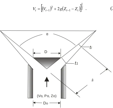
structure of the stream, it is required a symmetrical spray vertically upwards with dispersion angle α and average penetration. With these considerations a nozzle is chosen to operate with the highest pressure available, under a turbulent regimen flow, with a breaking mechanism corresponding to a hollow cone. The proposed model shown in Fig. 3 corresponds to a simple nozzle of conical film which is developed symmetrically and is progressively thinned until the breaking-up point. According to this model, it is possible to establish a method of design based on the principles of mass and energy conservation. From the schematic of Fig. 3 it is observed that the liquid film is thinned as it flows away of the exit nozzle. It is assumed that in some point, downstream, the film will be broken; therefore, it is possible to estimate the thickness t1 based on the inlet velocity . As
an initial condition to determine the thickness , it is necessary to know the thickness t1 and the velocity at the
exit of the nozzle. From the continuity and the energy equations, evaluated between points 0 and 1, the following equation can be obtained
0 4
2
4 2
0 1 2
1cos + CDt −D =
Ct α . (1)
Here, is the rate of velocity change obtained from the Bernoulli equation. Evaluation of the continuity equation between two points located downstream the nozzle gives
0 2 2
2
2 + − =
Q sen V t cos V
ti i i i
α π α
π , (2)
where subscript i indicates an arbitrary point downstream the
nozzle. Vi is the velocity obtained evaluating the Bernoulli
equation between points i and i-1 which is the preceding
point in the same direction of the flow, and Q is the initial
volumetric flow. By knowing the boundary conditions (t1,
V1), it is possible to determine the thickness of the film
based on the length and of the angle α by using Eq. (2). Then, velocity equation takes the form
( )
(
)
[
]
21 1 2
1 2 i i
i
i V gZ Z
V = − + − − . (3)
α
t1
ti
D
Do
li
(Vo, Po, Zo)
Fig. 3. Model of a spray of conical film generated by a baffle plate.
q
Catalyst at 600 °C
220 °C
Atomization
rad
Steam at 340 °C qconv
(a) (b)
Valve of the regenerated
catalys Cooler of thecatalys Valve of the exhausted catalyst Air distributor Line of the exhausted catalyst Regenerator Combustio gases
Vapor to the fractionator
Separator
Exhauster
Rise reactor
regenerator
[image:2.595.314.542.532.750.2]Eqs. (1)-(3) are very useful in the design of this type of nozzles, since they allow the evaluation of the film thickness for any cross-sectional section based on the angle and the outlet velocity.
III. EXPERIMENTALWORK
3.1 Methodology
The next step of the research is to make an initial design and build a scaling physical model for its evaluation in the laboratory. In order to assure dynamic similarity between model and prototype, the scaling parameter was the Reynolds number and an inner diameter relation of 1:4. Also, a scaling model of the reference prototype was built. Due to the difficulties to make experiments with the real fluid (gas oil), a substitute fluid was used, such that at room temperature this fluid had the same viscosity of the gas oil at the injection temperature to the reactor; it was found that water fulfilled this condition [11]. This criterion is valid considering that the viscosity forces are the greater opposing forces to the atomization process. It is worthy to note that, in practice, drops enter to a high turbulence flow where they break-up by coalition or by the action of the aerodynamic forces [1-10] ; this process continues until the complete vaporization of the gas oil is reached. Therefore, in this work only the of primary atomization process is evaluated, leaving for a later stage of the research the complete characterization of the spray.
3.2 Testing models
3.2.1 Reference nozzle
The original reference nozzle, named T-ORG, consists of a circular curved plate with a series of orifices as shown in Fig. 4. The flow passes through these orifices generating a high velocity circular jet.
3.2.2 Proposal models
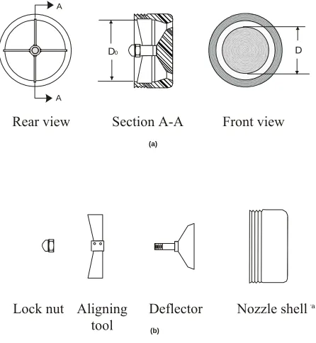
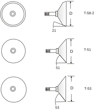
[image:3.595.318.540.286.418.2]The model shown in the Fig. 5 and its variants shown in the Fig. 6, for their identification, are named T-58-21, T-51 and T-53 respectively. The T-58-21 nozzle consists of a circular slot with a cross-sectional area and an output angle equivalent to the original reference nozzle, allowing the same outlet average velocity and pressure drop. The nozzle has a mechanism to align the flow giving symmetry to the cone formed by the fluid film. In relation to the T-51 and T-53 models, they are identified to have a wider angles of the baffle plate to produce spray of greater opening and smaller length of breaking-up.
3.3 Experimental installation
3.3.1 Test stand
The test stand consists of: A pump for water recirculation, a storage tank, a closed pipe system, a turbine to measure the water flowing through the test nozzle, a pressure transducer to measure the pressure drop through the nozzle and a manifold valve to control the flow through the nozzle. The water flows through the circuit, shown in the Fig. 7, pass through the nozzle, which is in vertical position and later
discharges in spray form into a cylindrical container. The spray discharges at opened camera allowing visualization of the flow in direct way as well as easy access to the measurement instruments.
3.3.2 System of flow measurement
For the measurement of water flow, a system that consists of a turbine, a signal transducer and a digital indicator was installed. This system has a precision of ± 0.5% and a repeatability of ± 0.1 % in relation to the reading, with a response time of 0.5 seconds.
3.3.3 System of images acquisition
The evaluation of the design of the nozzle was carried out through images taken systematically to an appropriate distance from the spray discharge. It is important to mention that this is a qualitative evaluation since it is based from a visual analysis of the images.
Fig. 4. Scaled model for the reference nozzle.
A A
Corte A-A Vista Frontal Vista posterior
Alineador Deflector Cuerpo de la tobera
D0 D
(a)
(b)
Tuerca de fijación
Fig. 5. Model of the testing nozzle T-58-21: a) Nozzle section and views b) parts diagram.
30
5 3 . 9 m m
123.6mm
21
Section A-A Rear view
a
a
Rear view Section A-A Front view
Lock nut Aligning
[image:3.595.316.539.499.741.2]21
51
53
T-58-21
T-53 T-51
D
D
[image:4.595.87.247.49.236.2]D
[image:4.595.63.270.295.423.2]Fig. 6. Deflector and its angle variations.
Fig. 7. Schematic diagram of the experimental stand.
The objective of this analysis is to verify the structure of the fluid film and drops formed at the outlet of the nozzle and its performance when varying flow velocity and make a comparison to the original nozzle. The equipment used for the experiments consists of a high resolution digital camera of 2080 × 1544 pixels, and a high speed video camera with a recording capacity of 3000 images per second at a shooting speed of 1/10000 seconds.
IV. RESULTS
A qualitative analysis of spray produced for the nozzle models T-ORG, T-58-21, T-51 and T-53 is presented. This analysis is based on photographic techniques and high speed videos; this evaluation emphasizes the film thickness of the liquid formed close to the nozzle, where the breakup-up point occurs and identifies the type of disintegration mechanism. The thinning of the film is evaluated through Eqs. (1)-(3). In addition, the hydrodynamics characterization of the four models is presented.
4.1 Disintegration process
In this section the pictures show the breaking-up mechanism of the fluid flow for the process of cylindrical and hollow
cone jets. Water flow was increased gradually reaching the complete disintegration of the jet.
4.1.1 Mechanism of disintegration for a circular stream
The pictures sequence of Fig. 8 shows the disintegration process for model T-ORG, which presents 12 water jets starting as solid cylinders. In Fig. 8a, the initial state of the primary atomization process can be observed, which is caused by the growth of the axial symmetrical oscillations at the jet surface and by the action of the surface tension of the fluid. Also it can be observed that the diameter of the drops exceeds to the diameter of the jet, which is characteristic of this flow regime. In Fig. 8b, the appearance of asymmetric oscillations is observed as a second state of disintegration. Also, it is observed the appearance of smaller drops than in the first state, which is to be expected when increasing the discharge velocity. Fig. 8c shows an advanced state of disintegration caused by a greater flow velocity than in the previous state. The jet is totally disintegrated becoming small drops, which is indicative of the flow regime called atomization.
4.1.2 Mechanism of disintegration for a conical film stream
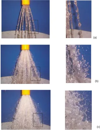
Figs. 9a, 9b and 9c show the first stage of the breaking-up process during the laminar flow regime. In this stage, the surface tension forces dominate the process producing a fluid form which is characteristic of this flow regime. Initially (Fig 9a), the fluid acquires an onion shaped flow, then, when flow velocity increases (fig 9b) the film is opened in the inferior part allowing air entrance towards the hollow and getting a tulip shaped flow, later (fig 9c), the film is completely opened acquiring the hollow cone pattern. These configurations are very important, since it is an indicative that the fluid is uniformly distributed through the cone. It is also observed that as the distance of the nozzle is increased, the film is perforated as a result of its thinning, which is typical when there is no rotational component in the jet. An intermediate regime appears when the discharge velocity was increased eight times the initial velocity. In Fig. 9d is observed that the influence of the aerodynamic forces begins to be important; big ligaments and drops appear in the zone near the nozzle without reaching total atomization. A third stage appears when the discharge velocity is increased to fourteen times the initial velocity. Images 9e and 9f show how the fluid film is broken-up in a zone very close to nozzle outlet, and then it becomes ligaments and drops, forming spray. This stage is known as atomization state, which is dominated by the action of the aerodynamic forces.
4.2 Spray evaluation
4.2.1 Effect of the angle of the conical deflector on the thickness of the film
The graph of Fig. 10 was obtained with Eqs. (2)-(3) and shows the film thickness through the cone formed by the stream. The computation was made for three discharge angles corresponding to 42º, 102º and 106º, maintaining a constant discharge velocity. This figure shows that the film thickness decreases in the flow direction and as the angle increases the film thickness decreases quicker, this means that the length of the breaking point of the film is highly dependent of the angle of the plate deflector, therefore, has to be considered for the design of this type of nozzles.
P
Nozzl Spray
Regulating Supplying
Supplying pump Recuperator
(a)
[image:5.595.83.253.51.271.2](c) (b)
Fig. 8. Process of disintegration for model T-ORG: a) Laminar flow, b) transition regime and c) atomization.
(a)
(f) (e)
(b)
[image:5.595.313.509.174.316.2](d) (c)
Fig. 9. Process of disintegration for a conical film stream: a) Onion shaped flow, b) tulip shaped flow, c) perforations in
the film, d) by friction of the air, e) and f) atomization.
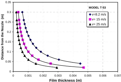
4.2.2 Effect of the velocity on the film thickness
In order to evaluate the effect of the velocity on the film thickness, as in the previous section, the calculation was made for different points downstream the nozzle (length l of
Fig. 3). The results for each model appear in Figs. 11 to 13. It is observed in these graphs that the film thickness decreases as the velocity increases. This behavior means that as the velocity is increased, the breaking-up point of the flow film will approach the outlet nozzle until reaching the atomization point. Actually, it is easy to visualize this point for laminar flow regime, see images of Figs. 9b and 9c, however, when
the flow is turbulent, this point is lost at sight and its location is very complex.
4.2.3 Hydrodynamics characterization
In this section the operation curves and the discharge coefficients obtained experimentally for each nozzle are displayed. The graph of Fig. 14 shows the curves of pressure vs. flow rate for T-ORG, T-58-21, T-51 and T-53 models.
0 0.05 0.1 0.15 0.2 0.25 0.3 0.35
0 0.001 0.002 0.003 0.004 0.005 0.006 0.007 Film thickness (m)
D
ista
n
ce
from
the
N
o
z
z
le
(m)
T-58-21, v = 8.2 m/s
T-51, v = 8.2 m/s
T-53, v = 8.2 m/s Deflector Angle
[image:5.595.80.257.341.576.2]106° 102° 42°
Fig. 10. Effect of the angle of the baffle plate on the film thickness.
MODEL T-58-21
0 0.05 0.1 0.15 0.2 0.25 0.3 0.35
0 0.001 0.002 0.003 0.004 0.005 0.006 0.007 Film thickness (m)
Distance from the Nozz
le (m)
[image:5.595.310.501.377.521.2]v = 8.2 m/s v= 15 m/s v= 25 m/s
Fig. 11. Effect of the discharge velocity on the film thickness T-58-21 model.
MODEL T-51
0 0.05 0.1 0.15 0.2 0.25 0.3 0.35
0 0.001 0.002 0.003 0.004 0.005 0.006 0.007 Film thickness (m)
D
istan
ce from
th
e N
o
z
z
le (m)
v= 8.2 m/s v=15 m/s v= 25 m/s
[image:5.595.310.521.596.738.2]MODEL T-53
0 0.05 0.1 0.15 0.2 0.25 0.3 0.35
0 0.001 0.002 0.003 0.004 0.005 0.006 0.007 Film thickness (m)
Dista
n
ce fr
om the Noz
z
le (m)
v=8.2 m/s v= 15 m/s v= 25 m/s
Fig. 13. Effect of the discharge velocity on the film thickness T-53 model.
0 0.002 0.004 0.006 0.008 0.01 0.012 0.014
0 0.2 0.4 0.6 0.8 1 1.2 1.4 Pressure (bar)
Fl
ow
Rat
e
(m3/
s)
[image:6.595.53.262.70.212.2]T-58-21 T-ORG T-51 T-53
Fig. 14. Operation curves obtained for water at room temperature.
0.4 0.5 0.6 0.7 0.8 0.9 1 1.1 1.2
100000 1000000
Reynolds Number Re
D
is
c
h
ar
g
e
C
o
e
ff
ici
en
t C
d
[image:6.595.57.264.303.447.2]T-0RG T-51 T-53 T-58-21
Figure 15. Discharge coefficient as a function of the Reynolds number based on the discharge slot.
Although models T-ORG, T-58-21 and T-51 have the same flow area, a displacement of the curves corresponding to the models T-58-21 andT-51 in relation to the T-ORG is observed. This displacement is very important, since it indicates a lower pressure drop for these models, which allows making adjustments to the flow area and the discharge angle without modifying the pumping system. A better parameter to evaluate the hydrodynamic behavior of the nozzles is the discharge coefficient defined as the ratio of the average flow rate and the ideal flow rate ( ). This coefficient appears in Fig. 15 as a function of the Reynolds number. As it is observed in this figure, there is a significant separation between the curves representing the conical slot and the curves of the model of circular orifices.
ACKNOWLEDGMENT
The financial support of DGEST, CONACYT and IMP is gratefully acknowledgment.
REFERENCES
[1] Rayleigh, Lord, “On the Instability of Jets”, Proc. London Math. Soc. Vol. 10, pp 4-13, 1878.
[2] Tyler, F., “Instability of Liquid Jets”, Philos. Mag. (London), Vol. 16, pp. 504-518, 1933.
[3] Weber, C., “Disintegration of Liquid Jets”, Z. Angew. Math. Mech. Vol. 2, pp. 136-159, 1931.
[4] Heinlein, A., “Disintegration of a Liquid Jet”, NACA TN 659, 1932.
[5] Ohnesorge, W., “Formation of Drops by Nozzles and the Breakup of Liquid jets”, Z. Angew. Math. Mech. Vol. 16, pp. 355-358, 1936.
[6] Reitz, R., “Atomization and Other Breakup Regimes of a Liquid Jet”. Ph.D. thesis, Princeton University, 1978. [7] York, J. L., Stubbs, H. F., and Tek, M. R., “The
Mechanism of Disintegration of Liquid Sheets”, Trans. ASME, vol. 75, pp. 1279-1286, 1953.
[8] Risk, N. K., and Lefebvre, A. H., “Influence of Liquid Film Thickness on Air blast Atomization”, Trans, ASME, Eng. Power, Vol. 102, pp. 706-710, 1980. [9] Eisenklam, P., “Recent Research and Development on
Liquid Atomization in Europe and U.S.A., 5th Conference on Liquid Atomization”, Tokyo, 1976. [10]Orzechowki, Z., “Liquid Atomization”, WNT, Warsaw,
1976.
[image:6.595.65.271.557.694.2]