Abstract—In Wireless era, Cross-layer designing of transmission power assignment and power control is the critical issues in emerging wireless technology. Intelligent transmission power selection algorithm depends on the notion of Transmission Power (TXPOWER), energy, Received Signal Strength Indication (RSSI) and the distance. The decentralized network without load balancing leads to network partitioning, route reliability, link failure and retransmission occurs. This power control Cross-layer design used for communicating information among the intermediate layers. LOADPOWR CONTROL Transmission power assignment algorithm in wireless networks leads to the network more efficient by using PWmin and PWmax power control technique. Euclidean distance calculates appropriate distance between sender and receiver in the network. Path loss model used to calculate difference between transmission power and received power for the amount of mobile nodes present in the LOADPOWER network. The key concept is to improve the network throughput, delay, distance, saves energy by sending all the packets with optimal transmit power according to the network load. Simulation was done in NS-2 simulator.
Index Terms— TXPOWER, RSSI, LOADPOWER
I. INTRODUCTION
MONG the entire communication network available today the popularity of wireless networks has been appreciated recently due to its wide range of applicability and versatility. It has revolutionized the science and technology and added comfort and beauty to the modern life. The complex technology made simpler and more user friendly due to the amalgamation of the wireless technology with the traditional wired equipments. The wireless technology is blended with our personal and professional life in the form of mobile telephony, wireless fidelity (Wi-Fi), Bluetooth, telemedicine and so on.
Manuscript received December 3, 2014; Revised February 10, 2015. (Article Submitted on November 19, 2014.) This work was supported in part by the UGC-BSR (Union Grant Commission) .
A. Arivoli is a research scholar with the Anna University, Department of Information Science and Technology; chennai-25; Tamilnadu, India. (Phone: 9486704045; e-mail: [email protected]).
Dr .P. Narayanasamy, was with professor in Anna University, He is now with the Department of Information Science and Technology; Chennai-25; Tamilnadu; India. (e-mail: [email protected]).
Now days, we are completely dependent on these type of device and applications for our comfort and necessity. Variety of wireless network exists ranging from most popular infrastructure based cellular networks, to most recent and advanced ad hoc and sensor networks [1].
Cross-layering of power control in ad hoc network is a set of nodes that have the ability to communicate wirelessly without the existence of any fixed infrastructure and mainly MAC and Network layer information are shared. Nodes in an ad hoc network use other nodes as intermediate relays to transmit packets to their destinations.
The node in wireless network acts as a router for communicating the information. Since nodes are usually battery operated, energy conservation is an important issue [2]. Transmission power assignment algorithm provides the best solutions for the initial power allocation in the wireless environment. Furthermore, because of the broadcast nature of the wireless medium, ad hoc networks are also limited by interference/capacity considerations. If power control is dealing in MAC layer IEEE802.11b stack build with the minimum and the maximum power values. According to that transmission power is denoted by TXPOWER, minimum power is PWmin and maximum power is PWmax.
Power control in Network layer provides the efficient power aware routing with the optimal transmission power and also provides the shortest path power routing. So in this transmission power assignment algorithm provide the power control solutions for both the MAC and the Network layer power control.
This proposed transmission power assignment algorithm based on power control techniques for single-hop and multi-hop wireless network. The challenges in this proposed work is, the selection of network is based on the load. If the load is low or high depends on the traffic and distance. For the calculation of distance between the sender and receiver Euclidean distance is used. Another technical challenge is to determine the appropriate power level for each and every node using the RSSI. When a sender transmits Node ANode B, the receiver measures the signal strength of a sender using RSSI. It also measures the power in the received radio channels. The proposed system model is PWmin and PWmax transmission power assignment
algorithm for both single and multihop wireless ad hoc networks. For the power assignment algorithm, power control techniques are used to describe the system. The clustering approach is also used to balance the maximum and the minimum power levels of the network.
Cross-Layer Design of Power Assignment
and Power Balance in Wireless Ad-hoc
Networks
A.Arivoli and P. Narayanasamy
II. POWER CONTROL IN WIRELESS AD HOC NETWORKS A. Power control
Power control has taken three directions:
1) Choosing a power level that will maintain network connectivity, bounding the number of one-hop neighbors.
2) Designing power efficient routing algorithms in the network layer.
3) Modification of the MAC layer to support a sleep mode The growth in the size of wireless networks also makes it desirable to use decentralized mechanisms for power allocation because centrally controlled mechanisms involve added infra-structure and network vulnerability was proposed by Shrutivandana Sharma et.al. Power control is intelligent selection of transmit power in a communication system to achieve good performance within the system. In [9] power management and power control techniques in wireless networks, with the emphasis on the energy conservation and performance tradeoff. Optimizing metrics such as a link rate, network capacity, coverage range and the life time of the network.
Further, if the ad hoc network is large consisting of thousands of nodes, collecting information from all the nodes and passing it to the concerned nodes lead to high overheads. Thus, distributed topology control algorithms that are asynchronous, scalable and localized are particularly attractive for ad hoc networks. The dynamic algorithm optimizes the overall energy consumption based on adaptive outage probability specification that guarantees the worst outage probability to all the users [8]. Once the nodes are deployed, it is very difficult or even impossible to recharge or replace their batteries in many application scenarios. Hence, reducing power consumption is often the only way to extend network lifetime. For the purpose of energy conservation, each node can (possibly dynamically) adjust its transmitting power between zero and its maximal transmission power [6]. Power assignment for wireless ad hoc networks is to assign a power for each wireless node such that the induced communication graph has some required properties. Recently research efforts have focused on finding the minimum power assignment to guarantee the connectivity or fault-tolerance of the network [7].Three energy efficient techniques to reduce energy consumption at protocol level. The first technique conserves energy by reducing number of route request packet while other two techniques suggest different approach to achieve that[5].
B. Motivation for cross-layer design
Cross-layer design is the promising and improvement of performance in the wireless technology. Cross-layer optimization defines a general concept of communication between layers, considering certain smart interactions between them, and resulting in network performance improvements. It aims in coupling the functionality of network layers with the goal of boosting system-wide performance. Traditional approach concerning OSI layered
model can recognize a subset of possible cross-layer interactions.
[image:2.595.302.533.81.281.2]
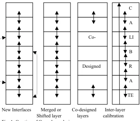
New Interfaces Merged or Co-designed Inter-layer Shifted layer layers calibration Fig. 1. Creation of Cross-layer design
In Fig. 1. Cross-layer or interlayer networking can be considered as one in which different layers of the network protocol stack inter-communicate the useful information so as to collectively achieve the desired vertical optimization goal. For the sake of QoS (quality of service) requirements varying with applications, the network or higher layers function should directly base on the information from the lower physical and MAC layers. Our work focuses MAC and network layer power control mechanisms. So many possible cross-layering designs can work in the wireless network but this work deals the cross- layer from physical to transport layer.
Steps:
1) First the new interfaces are created in the protocol stack.
2) Merging of shifted layers is done. 3) Merged layers are designed in the stack.
4) Inter-layer communication takes place using the shared information in the protocol stack
Design:
1) There exists the direct coupling between the physical and the upper layer.
2) In Cross-layer design, only to meet the fast growing demands.
3) Cross-layer design required to integrate all the layers. Cross-layer design is not a non-layered or single-layered design.
C. Energy management in LOADPOWER network
The below Fig. 2. Shows that energy management schemes. It broadly classified into three categories battery power management, transmission power management and system management. Our work focus on transmission power using both MAC and network layer cross- layer. MAC layer power control IEEE802.11b is a set of 802.11 that provides wireless transmission in wireless connectivity. Network layer provides a efficient power routing to optimize transmission power.
Co-
Designed
LI
A C
A
B R
Fig. 2. LOADPOWER energy scheme
D. Need for Power Management in Wireless Networks
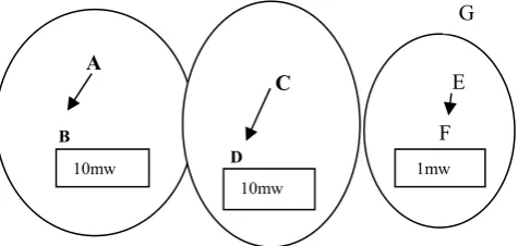
Power management and transmission power assignment is more crucial in wireless technology. Consider the network with node A, B, C, D, E, F, and G in Fig. 3.
Fig. 3. Power management in wireless network
1) Consider the network with 7 nodes A, B, C, D, E, F, and G and the communication range is specified for all the nodes present in the network.
2) Node A and Node C are transmitting at higher power level than node E. Communication only done between node A and node B or node C and node D. Otherwise collision may occur.
3) Node E communicates with Node F with lower power level and node G in the carrier sensing range in the network.
4) Carrier sensing range is two times than the transmission range
Carrier sensing range = 2times X Transmission range.
5) When A want to communicate B with higher power level, consequently E communicate with F with lower power level, it leads to collision.
III. BACKGROUNDANDRELATEDWORK A. Power assignment and transmission scheduling According to [3]. Transmission scheduling algorithm must have two components to solve the two sub problems of power assignment and transmission scheduling. Two
types of downlink data transmission scheduling algorithms are proposed. In the first type, power assignment is performed before transmission scheduling. In the second type, power assignment is performed after transmission scheduling. The performances of two algorithms of the first type which use the equal power allocation method are analyzed. It is shown that both algorithms exhibit excellent worst-case performance and asymptotically optimal average-case performance under the condition that the total transmission power is equally allocated to the channels. In general, both algorithms exhibit excellent average-case performance. It is demonstrated that two algorithms of the second type perform better than the two algorithms of the first type due to the equal time power allocation method.
1) Power Assignment – EQ (Equal Power allocation) First type of downlink data transmission scheduling algorithms are developed based on the method of equal power (EP) allocation. If the total transmission power P is equally allocated to the C channels and the n transmission requests in refer “(1),”
Pi = γ = P /C (1) for all 1 ≤ i ≤n, where i is the average power per channel.
2) Power Assignment – ET (Equal Time Allocation) Second type of data transmission scheduling algorithm based on the observation. In an optimal schedule, all the channels 1, 2, ..., C complete their data transmissions simultaneously. The above theorem is easy to prove. Assume that (si, di) is the last completed transmission request which is allocated power pi, and (sj , dj) is the second last completed transmission request which is allocated power pj. It is clear that we can always increase pi and reduce pj such that the two transmissions are finished at the same time and that the total transmission time is reduced in refer “(2),”Therefore, we need to find p1, p2, ..., pC and T such that in
T1(p1) = T2(p2) = ∙∙∙ = TC(pC) = T (2)
B. Power allocation in Multi-user relay network According to [4] Multi-user single relay wireless network, where the relay facilitates transmissions of the users’ signals to the destination. Consider a wireless network with N users communicating with their destinations with the help of one relay as shown in Fig. 3. Denote the channel from User i to the relay as fi, the channel from User i to Destination i (the direct link) as hi, and the channel from the relay to Destination i as gi. We consider two channel models in this paper, Rayleigh flat fading channel and path-loss channel
Energy management Scheme
Data link layer Network layer Transmission power management
Cross-layer design
A
B
C
D
E F
G
10mw
[image:3.595.50.288.333.446.2]
Fig. 4. Multi-user relay network.
IV. PROPOSED NETWORK – PWMIN AND PW MAX FORLOADPOWERCONTROLTRANSMISSION
POWER ASSIGNMENT ALGORITHM
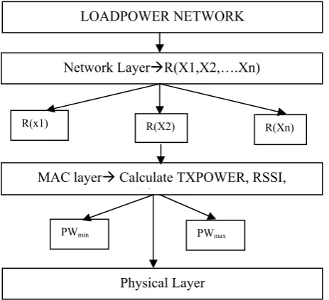
According to Fig. 5. The Load power domain is running in the network layer R(X1, X2, ….Xn). Each node in the LOAD POWER network find out the individual power level, when the transmission takes place. In this work power allocation done both in MAC and network layer using cross- layer design. RSSI is calculates received signal strength in received nodes in network. Each node assigns its individual power according to the Pmin and Pmax power control technique. The transmission power is set for the data packets and the power level is changed for every individual packet in the network. In the network layer, the power route module consists of DEST, NEXTHOP, METRIC and TXPOWER and AC
[image:4.595.52.284.515.726.2]
Fig. 5. Cross-layer design of LOADPOWER network model.
Power balancing algorithm is used to balance the nodes participate in the overall networks. Clustering technique is used to balance the network nodes. Power assignment with power balancing also done in this cross-layer design. The
following transmission assignment algorithm proves power level can be changes due to the heterogeneity in the network. For Example when node A want to send the Transmission Power to B with high power level but not necessary when B send A to the same power value
A. Path loss model
The basic power loss model that we use is a simplification of the one proposed in the path loss of a wireless link can be represented by the difference between the transmit power PWtx and receive power PWrx in refer “(3)”,
Path Loss = PWtx – PWrx (3) In this expression, we are grouping a variety of effects, including multipath fading, shadowing, and path loss, under the general term “Path Loss”. This term describes the collective effect of these individual wireless loss mechanisms in reducing the transmitted power down to the received signal strength.
B. Algorithm – Assignment of transmission power
Fig. 6. Transmission from A to B
Fig. 6. Shows that assignment of transmission power from A to B and B to A. Sender sends a packet to B with higher power PWmax and receiver sends lower power level PWmin.PW (AB) ≠ PW (BA) (4)
In Asymmetric link transmission power used in assignment power refers “(4)”.
Source:
1. Listen for the packet for the optimal transmission power level
2. Assign the transmit power for the receiver Destination:
1. Receive the data packets from the source, calculate the RSSI of the packet from the source node 2. If(sender is not ready in the list of nodes for which
RSSI is unknown {
Add the sender to the list then record RSSI }
3. If(sender is on the list of the node for which the initial transmission power of the sender is unknown)
{
Then use the initial transmission power of sender in step 4.
} Else R(X2)
LOADPOWER NETWORK
Physical Layer
Network LayerR(X1,X2,….Xn)
MAC layer Calculate TXPOWER, RSSI, Di
PWmin
R(x1) R(Xn)
PWmax
a b
Relay
User N
User i
User 1
Destination 1
Destination i
Destination N f1
gN gi fi
fN
hi
hN
g1
{
Still need control packets from sender with record of the initial transmission power Exit
}
4. Calculate the new optimal transmission power level Topt.
5. Update the table with the newly calculated power Topt
6. Send the new Topt to sender if RSSI has changed
significantly of there is a time out.
C. Algorithm for PWmin and PWmax transmission power assignment Technique in single hop wireless network
Fig. 7. Power control technique- single hop network
Fig. 7. Shows algorithm for single hop wireless network. Input: Single hop wireless network N
Output: Finding the power level for a to b Begin
for each P (ab) do
Calculate the PWmin (a) and PWmax (a) and also/* for node a
Calculate the PWmin (b) and PWmax (b) /* for node b
Calculate the P (ab) by Euclidean distance
Transmit the min or max power from a to b /* a find the optimal power level to b
End
D. Algorithm for PWmin and PWmax transmission power assignment Technique in multi hop wireless network
[image:5.595.305.538.473.642.2]
Fig. 8. Power control Technique – Multi-hop network.
In Fig. 8. Shows the power control algorithm in multi-hop network
Input: Multi hop wireless network N Output:Finding the power level for a to b
Begin
for each P (ab) do
Calculate the PWmin (a) and PWmax (a) and also /* for node a
Calculate the PWmin (b) and PWmax (b) /* for node
b
Calculate the P (ab) by Euclidean distance If p (ac) +p (cb) ≤ p(ab)
then transmits with p (ac) for b
else transmits with p (ab) for b End.
E. Euclidean distance
Euclidean distance is distance between two points, two nodes such as sender transmission power PWrx and the receiver transmission power PWtx can be calculated by Euclidean distance. It is used to measuring the distance between the sender and receiver in the wireless network environment.
Distance between PWtx and PWrx for two nodes a and b is denoted by,
a = (a1, a2, ……..an)
b = (b1, b2, .…….bn)
Equation, “5” and “6”, the distance between a to b and b to a is denoted by,
d (a, b) =d (b, a) = (5) = (6)
V. RESULTSANDDISCUSSION A. Throughput, Delay for LOADPOW Protocol LOADPOW Throughput - Time (Vs) Number of Packets
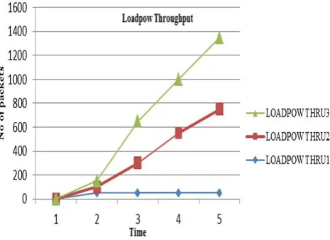
In Fig. 9. LOADPOW Protocol throughput for varies for source and destination. In our simulation, considering 3 sources and destination.
Fig. 9. LOADPOW Throughput
Based on the source and destination throughput differs in throughput. First and source and destination increases the throughput based on transmission power and Asymmetric routes. But the final source and destination decreases the throughput due to lower transmission power. But the overall throughput is increasing in LOADPOW Protocol.
a P (ab) b
a P(ab) b
c
P(ac) P(cb)
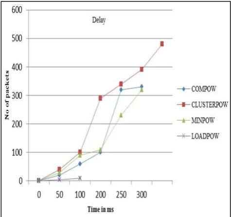
[image:5.595.50.270.492.610.2]B. LOADPOW Delay – Time (Vs) Number of Packets In Fig. 10. LOADPOW Delay considering 3 sources and destinations. Delay varies for various source and destination. Delay varies according to transmission power. In LOADPOW it uses the independent power, but first source and destination increases the delay and the second and third decreases the delay. So the overall delay is reduces the end to end delay in the network.
Fig. 10. LOADPOW Delay
VI. CONCLUSION
Transmission power assignment algorithm in wireless network is more important due to the mobility of the network infrastructure. This paper shows how to assign the power in single and multihop wireless network. Dealing with network load, RSS, Path loss model in cross-layer design. The decentralized network without load balancing leads to network partitioning, route reliability, link failure and retransmission occurs. This power control Cross-layer design used for communicating information among the intermediate layers. Trivial node selection is the method of identifying the unbalanced nodes and the network to optimize the power. The particular node load balancing plays as a Hotspot in the network region as a future enhancement in power control ad hoc network.
REFERENCES
[1] C.E.Perkins, ‖Ad Hoc Networking,‖ Addison Wesley, 2001 [2] Shrutivandana Sharma and Demosthenis Teneketzis, Fellow, IEEE.
An Externalities-Based Decentralized Optimal Power Allocation Algorithm for Wireless Networks. Acm transactions on networking, VOL. 17, No. 6, december 2009.
[3] Keqin Li. Power Assignment and Transmission Scheduling in Wireless Networks . IEEE 2010.
[4] Qian Cao, Yindi Jing, and H. Vicky Zhao. Power Allocation in Multi- User Wireless Relay Networks through Bargaining. IEEE transactions on wireless communications, VOL. 12, NO. 6, June 2013.
[5] Niranjan Kumar Ray, Ashok Kumar Turuk. Energy Efficient Techniques for Wireless Ad Hoc Networks. First international on information and communication technology, IJcICT 2010. 105-111, January 2010.
[6] Xiaohua jia, Dongsoo kim, Power Assignment in K-connectivity in wireless ad hoc networks. Journal of Combinatorial Optimization, Springer. 9, 213–222, 2005
[7] Yu Wang Minimum Power Assignment in Wireless Ad Hoc Networks with Spanner Property. Kluwer Academic Publishers. Printed in the Netherlands. 2005.
[8] Chee Wei Tan. Optimal Power Control in Rayleigh-fading Heterogeneous Networks IEEE INFOCOM 2010. City University of Hong Kong.