Robust Programmable-Rate Wireless Graphical
Correspondence
LAJOS HANZO, ANDY H. YUEN
Dept. of Electr. and Comp. Sc., University of Southampton Mountbatten Builaing, 4003, SO17 lBJ, UK
Abstract. An adaptive fixed-length differential chain coding (FL-DCC) scheme is proposed for the transmission of line graph- ics, which canbe re-configured as a lower rate, lower resolution or higher rate. higher resolution source codec. Compared to Differential Chain Coding (DCC), the proposed FL-DCC codec has a lower coding rate in both of its lower- and higher-rate operating modes, while maintaining a similar subjective graphical quality.The dual-rate re-configurable FL-DCC codec is embedded in a voice, video multimedia communicator system, which allocates the FL-DCC graphics packets Lo idle speech packets with the aid of the Packet Reservation Multiple Access (PRMA) multiplexer. In a bandwidth of 200 kHz, which is characteristic of the Pan-European GSM system, nine speech, video and graphics multimedia users can be accommodated using bandwidth efficient 16-level Quadrature Amplitude Modulation (16QAM) over benign ~nicrocellular channels.Under less favourable propagation conditions the more robust, but less bandwidth efficient 3QAM mode of operation can be invoked. In the diversity-aided and automatic repeat request (ARQ) assisted I6QAM mode of operation the multimedia user bandwidth becomes 22.2 kHz and the minimum required channel signal to noise ratio ( S N R ) over AWCN and Rayleigh chan- nels is about 11 and 15 dB, respectively. The most salient system features are summarised in Table 2.
Telewriting is a multimedia telecommunication ser- vice enabling the bandwidth-efficient transmission of handwritten text and line graphics through fixed and wireless communication networks [2, 41. Differential chain coding (DCC) has been successfully used for graphical communications over E-mail networks or teletext systems [I], where bit rate economy is achieved by exploiting the correlation between successive vec- tors. A plethora of further excellent treatises were con- tributed to the literature of chain coding by R. Prasad and his colleagues from Delft University [ I , 51.
In this contribution an intelligent re-configurable graphical communications scheme is contrived, which is embedded in a voice, video multimedia system context. In the proposed fixed-length differential chain coding (FL-DCC) scheme the number of bits used to quantise the differential vectors of the so-called coding ring is dynam- ically adjusted under system's control, in ordei to match the prevailing bitrate, graphical quality andlor channel quality constraints. Our efforts are in line with the European Research in Advanced Communications Equipment (RACE) project's Advanced Communications Technologies and Services (ACTS) programme [6] to define a flexible third generation standard, backwardly compatible with second generation systems, while pro- viding more advanced future features. The adaptivity of the transceiver can be exploited in numerous ways on a more static or dynamic basis, but these algorithms form
part of the higher-level functions of the classic seven- layer architechture. This contribution will concentrate on the physical layer functions, establishing the principle and documenting the expected performance of the adaptive graphical transceiver, while leaving the issues of re-con- figuration algorithms for future studies. Although during low bitrate operation our transceiver uses lossy quantisa- tion, we will demonstrate that in case of small coding rings near-unimpaired subjective quality is maintained.
The paper is structured as follows. Section 2 high- lights the system's architecture, leading to section 3, which describes the proposed re-configurable graphical source codec. The codec's robustness against channel errors is increased using a technique described in sec- tion 4. Transmission issues, including error control, modulation and packetisation aspects are discussed in section 5 . Section 6 is devoted to issues related to multi- plexing graphical source signals with voice and video, before reporting on the system's performance in section 7. Our conclusions are offered in section 8.
The proposed system's architecture is shown in Fig. 1, where the voice, video and graphics source encoders' bit streams are mapped in two sensitivity classes and sensi- tivity-matched binary Bose-Chaudhuri-Hocquenghem (BCH) forward error correction (FEC) coded [ 1 I]. Then both the more vulnerable Class One and the more robust
1
Z g eI,
EncoderEncoder PRMA MPX
CI. Two E~coder
Graphics
Decoder
4
I Decoder 1
1
Postprocessing 1- [image:2.473.6.226.32.238.2]Handover, ARQ
Fig. I
-
System's schematic.Class Two source bits are fed to the Packet Reservation Multiple Access (PRMA) [ I 31 Multiplexer (MPX) and queued for transmission to the Base Station (BS). Depending on the channel conditions, Pilot Symbol Assisted (PSA) 4-level or 16-level Quadrature Amplitude Modulation (QAM) [13] is invoked, allowing for the system to increase the number of bits per symbol within the same bandwidth and hence to improve the voice, video or graphics communications quality under benign channel conditions [9]. The receiver carries out the inverse functions and recovers the transmitted informa- tion. Should the communications quality unacceptably degrade, then the error detection capability of the stronger BCH code can be used to initiate a handover or Auto- matic Repeat Request (ARQ).
Specific issues of low-rate voice coding are consid- ered for example in [ 101, while an intelligent multimode voice transceiver is proposed in reference [14]. In our current system a programmable-rate 814 kbitls Code Excited Linear Predictive (CELP) speech codec is assumed [16] for the purposes of networking studies, but speech coding aspects are not considered here. A range of adaptive video source codecs and videophone transceivers have been proposed in references 11 51, which produce an arbitrarily programmable, but con- stant rate 814 kbitls video sequence. Hence these codecs are ideally suited for videophony over conventional voice channels. Again, for our newtorking studies the 8 kbitls videophone scheme of reference 1151 is assumed, but the discussion of specific videophony aspects is beyond the scope of this treatise ( l ) . Having reviewed
the system's architecture let us now concentrate on the graphical source coding issues.
( I ) For further information concerning voice and video Lransmission issues the interested r r a d r r is referred lo Lhe WWW home-page
hup://www-tnobile.ecs.soton.ac.uk.
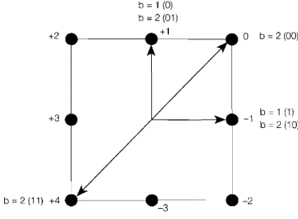
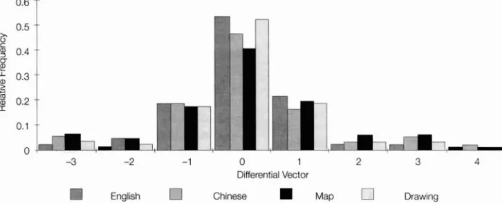
In chain coding (CC) a square-shaped coding ring is slid along the graphical trace from the current pixel, which is the origin of the legitimate motion vectors, in steps represented by the vectors portrayed in Fig. 2. The bold dots in the Figure represent the next legitimate pix- els during the graphical trace's evolution. In principle the graphical trace can evolve to any of the surrvunding eight pixels and hence a three-bit codeword is required for lossless coding. Differential chain coding [2, 41 (DCC) exploits that the most likely direction of stylus movement is a straight extension, with a diminishing chance of 180" turns. This suggests that the coding effi- ciency can be improved using the principle of entropy coding by allocating shorter codewords to more likely transitions and longer ones to less likely transitions. This argument is supported by the histogram of the differen- tial vectors of a range of graphical source signals, includ- ing English and Chinese handwriting, a Map and a tech- nical Drawing, portrayed in Fig. 3, where vectors 0, +1 and -1 are seen to have the highest relative frequency.
In this treatise we embarked on exploring the potential of a novel graphical coding scheme dispensing with the variable length coding principle of conventional DCC codecs, which we refer to therefore as fixed length diffe- rential chain coding (FL-DCC). FL-DCC was contrived in order to comply with the time-variant resolu\-tion- andlor bit rate constraints of intelligent third-generation adaptive multimode terminals, which can be re-config- ured under network control to satisfy the momentarily prevailing tele-traffic, robustness, quality, etc system requirements. In order to maintain lossless graphics qual- ity under lightly loaded traffic conditions, the FL-DCC codec can operate at a rate of b = 3 bitslvector, although it has a higher bit rate than DCC. However, since in voice and video coding typically perceptually unim- paired lossy quantisation is used, we embarked on exploring the potential of the re-configurable FL-DCC codec under b < 3 low-rate, lossy conditions.
Based on our findings in Fig. 3 as regards to the rela- tive frequencies of the various differential vectors. we
Fig. 2
-
Coding ring. [image:2.473.245.462.558.718.2]-3 -2 -1 0 1 2 3 4
Differential Vector
[image:3.527.47.410.37.184.2]English Chinese Map Drawing
Fig. 3
-
Relative frequency of differential vectors %for a range of dynamographical source signals.decided to evaluate the performance of the FL-DCC codec using the b = 1 and b = 2 bitlvector lossy schemes. As demonstrated by Fig. 2 , in the b = 2 bit mode the tran- sitions to pixels
-2,
-3, +2, +3 are illegitimate, while vec- tors 0, +1, -1 and +4 are legitimate. In order to rninirnise the effects of transmission errors the Gray codes seen in Fig. 2 were assigned. It will be demonstrated that, due to the low probability of occurance of the illegitimate vec- tors, the associated subjective coding impairment is minor. Under degrading channel conditions or higher tele-traffic load the FL-DCC coding rate has to be reduced to b = 1, in order to be able to invoke a less band- width efficient, but more robust modulation scheme or to generate less packets contending for transmission. In this case only vectors +I and -1 of Fig. 2 are legitimate. The subjective effects of the associated zig-zag trace will be removed by the decoder, which can detect these charac- teristic patterns and replace them by a fitted straight line.In general terms the size of the coding ring is given by 2 n T, where n = 1, 2 , 3
...
is referred to as the order of the ring and z is a scaling parameter, characteristic of the pixel separation distance. Hence the ring shown in Fig. 2 is a first order one. The number of nodes in the ring is M = 8n.The data syntax of the FL-DCC scheme is displayed in Fig. 4 . The beginning of a trace can be marked by a typically 8 bit long pen-down (PD) code, while the end of trace by a pen-up (PU) code. In order to ensure that these codes are not emulated by the remaining data, if this would be incurred, bit stuffing must be invoked. We found however that in complexity and robustness terms using a 'vector counter' (VC) for signalling the trace-length to the decoder constituted a more attractive alternative for our system. The starting coordinates Xo,
Yo of a trace are directly encoded using for example 10 and 9 bits in case of a video grahics array (VGA) reso- lution of 640
x
480 pixels.The first vector displacement along the trace is encod- ed by the best fitting vector defined by the coding ring as the starting vector (SV). The coding ring is then trans- lated along this starting vector to determine the next vec- tor. A differential approach is used for the encoding of
all the following vectors along the trace, in that the dif- ferences in direction between the present vector and its predecessor are calculated and these vector differences are mapped into a set of 2b fixed length b-bit codewords, which we refer to as 'fixed vectors' (FV). We will show that the coding rate of the proposed FL-DCC scheme is lower forb = 2 and b = 1 than that of DCC.
When a curve is encoded by FL-DCC, it is sliced by the coding ring into small segments. Consider a sampled curve segments. Let v be the vector link produced by the coding ring. The coding rate of a chain code is defined [I, 31 in bits per unit length of the curve segment as
x,
where b (s, v ) is the number of bits used to encode a vector link v, l,(s) is the length of the curve segment s, while E(x) represents the expected value of a random variable x. It has been shown [ 4 ] that for the set of all curves, the product of a segment length l,(s) and the probability p ( a ) that this segment occurs with a direc- tion alpha must be constant. Thus the expected curve segment length for a ring of order n is given by [ 2 ]
[image:3.527.245.457.223.257.2]Therefore, the theoretical coding rate of FL-DCC becomes:
Fig. 4
-
Coding syntax.n
Yo
The theoretical and experimental coding rates of the b = 1 and b = 2 FL-DCC schemes are shown in Table I .
Vo1. 8, No. 3 May
-
June 1997 273vc sv FV
...
...
x . . , .. . ' .
. . , . . E Z > . , ! , , . . . . . . , , r . . . ) I . . . , . , . " " . " , . . . ? . > . . ' . . . . . . , ) " I " " , "I I b , ?~ . , . . * , . . ?
. "
. . ,.' , " . . . * . , \ , "\ , .. ' . . . . , . ,
. . a . . .. .,< .. . ' . . ? . . . . . ' . . . I . '
< " \ . . " " .
..
, 8Table 1 - Coding rate comparison
In the next Section we endeavour to improve the robust- ness of the FL-DCC arrangement introduced, before transmission issues are considered.
English script
Chinese script
Map
Drawing Theoretical
4.
ROBUST
FL-DCC
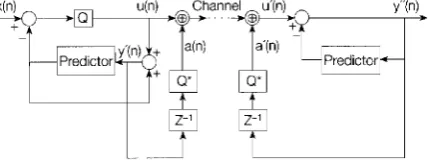
It is well understood that the objective and subjective effects of transmission errors is different in memoryless coding schemes, such as for example Pulse Code Modulation (PCM), and in predictive schemes, such as Differential PCM (DPCM) [7, 81. Our proposed FL-DCC scheme is to a certain extent related to DPCM, since it uses the previous vector as a prediction of the current one. This similarity prompted us to invoke a hybrid PCM- DPCM-like technique suggested by Bull [7, 81 in order to improve the robustness of the FL-DCC codec using the schematic of Fig. 5.
Bull's hybrid scheme [7] is adopted in our FL-DCC scheme as fo1lows.A~ it is demonstrated by the Figure, the h bit FL-DCC codeword u(n) is modified before transmission by modulo-2h adding the quantity a(n), which is derived from the locally decoded graphical sig- nal y '(n) by delaying it and taking the b Most Significant Bits (MSBs) of it. which is carried out by the quantiser Q*. Note that the modulo-2b addition truncates the result of the operation, which introduces some grade of arith- metic inaccuracy in comparison to an arithmetic treating overflows, but ensures that the transmitted codeword is still represented by b bits. Under error-free conditions the encoder and decoder are perfectly "aligned" with eachother, implying that u(n) = a'(n), u(n) = u'(n) and y "(n) = y '(n), which naturally allows unimpaired graph-
b = 1 bidvector
0.8535
0.8532
0.8536
0.8541
0.9
Predictor
'
6
- q
Fig. 5 - Robust FL-DCC acheme.
b = 2 bithector
1.7271
1.7554
1.7365
1.79 1 1
1.80
ical signal reconstruction, since the decoder carries out the inverse operations of the encoder.
In case of channel errors, however, the encoder and decoder become misaligned, but the proposed arrange- ment mitigates the propagation of transmission errors in the feed-back loop, as we will highlight in our forth- coming discourse. Let us assume that the decoded graphical signals at the encoder and decoder, namely y '(n) and y"(n), respectively, now differ at the sam- pling instant n due to transmission errors by the non- zero error quantity
DCC bidvector
2.0216
2.0403
2.0396
1.9437
2.03 e (n) = y '(n) - y "(n) (4)
Since the quantities a(n) and a'(n) are derived from y '(n) and y "(n) by coarse quantisation using Q*, the dif- ference a (n
+
1) - a ' (n+
1) at instant n+
1 consitutes a good measure of the error's influence at instant n+
1,because the decoded signals are delayed by one sam- pling interval. Bull [7] showed that the errors' effect can be substantially mitigated at sampling instant n
+
1, which will be demonstrated below, for the sake of con- ceptual simplicity assuming infinite precision addition, rather than modulo-2b truncation. From eq. (4) we have:and by the help of the decoder's inner predictor loop of Fig. 5, which is constituted by a one-sample delay, we can proceed to sampling instant n
+
1 to arrive at:and substituting y "(n) from eq. (5) into eq. (6):
We argued above that the difference a (n
+
I) - u'(n+
1) is a good measure of the error's influence at instant n+
I , hence u '(n+
1 ) in eq. (7) can be written as:and substituting eq. (8) back in eq. (7), while exploiting thata (n
+
1 ) - a ' ( n + l)=e(n)leads to: [image:4.473.2.229.49.195.2] [image:4.473.9.225.633.713.2]5.
TRANSMISSION
ISSUES 5.2. Modulution uspect~5.1. Error control
Trellis coded modulation (TCM) or block coded mod- ulation (BCM) have been proposed in the literature in order to reduce the required channel SNR [18, 191, while in [20] source-matched joint source/channel coding and modulation providing un-equal error protection was intro- duced. This was achieved by exploiting that the so-called maximum minimum distance square-shaped 16-QAM constellation exhibits a higher- and a lower-integrity sub- channel, naturally amenable to accommodate higher- and lower-sensitivity bits, respectively. This property was analysed in depth in [13]. In this treatise we will follow a similar design philosophy in order to achieve best system performance over fading channels [9].
Convolutional codes achieve their highest coding gain when relying on soft-decision decoding [ l l ] . They do not retain reliable error detection capabilities and hence they are often combined with an external error detecting block code, as in the GSM system [12]. In contrast, high minimum-distance block codes have a highly reliable error detection capability 11 I], which is a useful feature in terms of monitoring the channel's quality in order to activate Automatic Repeat Requests (ARQ), handovers or error concealment. Based on these arguments in our system we favoured binary Bose-Chaudhuri- Hocquenghem (BCH) codes [l 1
1.
which conveniently curtail channel error propagation across consecutive graphical traces. Although the soft-decision based trellis decoding of short block codes is potentially feasible in implementational complexity terms, the additional per- formance gain does not fully justify the complexity investment. This issue was illustrated in the contexl of the short BCH(15, 11, 1) code in [I I]. When a higher complexity and interleaving delay are acceptable, the employment of the iterativelydecoded so-called turbo codes proposed by Berrou [21] and refined for example by Hagenauer et a1 1221 is more beneficial in perfor- mance terms, achieving a performance close to the pre- dictions of Shannonian information theory. For the sake of low complexity in this treatise we opted for conven- tional Berlekamp-Massey-Forney hard-decoding [ l 11.The system's performance can be further improved using Automatic Repeat Request (ARQ) techniques, if the associated increased delay is acceptable and there are un-used time slots available. Due to their delay and the additional requirement for a feed-back channel for message acknowledgement ARQ techniques have not been employed in the past in interactive speech or video communications. In our Packet Reservation Multiple Access (PRMA) system however there exists a full duplex control link between the BS and PS, which can be used for acknowledgements and the short PRMA frame length and microcellular propagation delay guar- antee a low packet delay, therefore the employment of ARQ becomes realistic.
Vul. 8, Nu. 3 May -June 1997
In second-gcncration mobile radio systems, such as for example the Pan-European C S M system [12] or the Digital European Cordless Telecommunications (DECT) scheme, non-linearly amplified constant envelope partial response modulation techniques have often found favour. Specifically, Gaussian Minimum Shift Keying (GMSK) has been advocated due to its spectral compactness and innate robustness against fading and amplifier non-linear- ities. However, in recent years researchers have turned their attention towards the concept of the Intelligent Multimode Terminal (IMT) [6], which by optimally reconfiguring itself in order to satisfy dynamically chang- ing system optimisation criteria, achieve a better overall system performance. Spectral economy is further improved using micro- and pico-cellular structures, which exhibit friendly propagation properties and hence multi- level modulalion schemes can be invoked in order to fur- ther increase the teletraffic delivered, as in the American IS-54 and the Japanese Digital Cellular (JDC) system.
A further advantagc of linearly amplified multi-level modems is that they conveniently lend themselves to channel-quality or teletraffic-induced signal constellation re-configuration, an issue treated in depth for example in Chapter 13 of [13]. In order to complement the proposed multi-rate FL-DCC graphical source codec we designed a re-configurable modem. The most robust but leas1 band- width efficient 4-level Quadrature Amplitude Modulation (4QAM) [I31 mode can be used in outdoors scenarios in conjunction with the b = 1 mode of the FL-DCC codec. The less robust but more bandwidth efficient 16QAM mode may be invoked in friendly indoors cells in order to accommodate the b = 2 mode of operation of the FL- DCC codec. When the channel conditions are extremely favourable, the modem can also be conrigurcd as a 64QAM scheme, in which case it can deliver b = 3 bits per FL-DCC vector, allowing lossless coding. When using coherent PSAM [23], typically 3 dB lower channel signal-to-noise ratio (SNR) is sufficient over AWGN channels than in case of non-coherently detected lower- complexity StQAM modems [13], hence here we favour diversity-aided rectangular PSAM schemes [ 13, 231.
Wiener filter to minimise the channel estimation error variance. However, this computationally demanding technique has a similar performance to the conventional sinc-interpolator. In our quest for the best interpolator we found [17] that a simple polynomial interpolator had a similar performance to the above mentioned more complex schemes in terms of both mean squared esti- mation error as well as BER performance.
5.3. Packetisation aspects
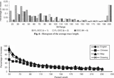
In order to determine the desirable length of the transmission packets, in Fig. 6 we evaluated the histo- gram of the average trace length, which exhibited a very long low-probability tail. This tail probability was rep- resented by the bars at an encoded trace-length of 200 bits in the Figure. Observe furthermore that, as expect- ed, the highest concentration of short traces was record- ed for b = 1, which was followed by b = 2 and the DCC mode of operation. However, most traces generated less than a few hundred bits, even when b = 2 was used. In order to be able to use a fixed packet length, while maintaining robustness against channel errors and cur- tailing transmission error propagation across packets and/or traces, we decided to tailor the number of bits per trace to the packet length of 222 bits. If a longer trace was encountered, it was forcidly truncated to this length and the next packet started with a new 'artificial' pen-down code. If, however, a shorter trace was encountered, a second trace was also fitted in to the cur- rent packet and eventually truncated to the required length for transmission. Unfortunately, the additional forcidly included VC code and the Xo, Yo coordinates
portrayed in Fig. 4 increased the number of bits generat-
ed but mitigated the error propagation effects. The pro- portion of the bit rate increase evaluated in terms of % for various packet lenghts in case of the FL-DCC b = 1 scheme is portrayed in Fig. 7.
Recall that the C1 16QAM subchannel had a factor 2-3 times better BER than the
C2
subchannel. This ratio would remain approximately the same if we were to use the same FEC code in both subchannels, but the C2 BER would remain excessively high for the transmission of the starting vectors (SV) and fixed-length vectors (FV) of Fig. 4. The BCH(255,13 1,18) and BCH(255,91,25) codes were found to ensure the required balance between the more and less robust FL-DCC bits, when employed in the C1 andC2
16QAM subchannels, respectively. In other words, employing the more powerful BCH(255,91,25) codec in the higher-BER C2 16QAM subchannel reduced the integrity difference between the subchannels and ensured the required source-sensitivity matched unequal error protection. The 2x
255 = 510 BCH-coded bits constitute 128 4 bit 16QAM symbols. After adding 14 pilot symbols according to a pilot spac- ing of 10 and concatenating 4 ramp symbols for smooth power amplifier ramping in order to minimise the out-of- band emissions the resulting 146-symbol packets are queued for transmission to the BS. The same packet for- mat can be used for the voicelvideo packets. Both the voice and the video codecs generate in their 8 kbitls mode of operation 160 bits120 ms frame and hence the 222 bit packet can accommodate a 62 bit signalling and control header in each 146-symbol packet. The corre- sponding single-user voicelvideo signalling rate becomes 146 symbols120 ms = 7.3 kBd. Due to their significantly lower rates and higher delay tolerance graphical users assemble their 146-symbol transmission packets over az
0.25 2 0.2c
5 00.15
Q
0.1-
0.05
0
20 30 40 50 60 70 80 90 100 110 120 130 140 150 160 170 180 190 200
Bit Range
FL-DCC (b = 1) FL-DCC (b = 2) W DCC (M = 8)
Fig. 6
-
Histogram of the average trace length.0 1 I
50 70 90 110 130 150 170 190 210 230 250
[image:6.472.50.421.455.710.2]Packet Length
longer period, before their transmission. The issue of maximum achievable graphical data rate will be addressed in the Results Section.
When using a bandwidth of 200 kHz, as in the Pan- European mobile radio system known as GSM [I21 and a modulation excess bandwidth of 50 % or a Nyquist roll-off factor of 0.5, a signalling rate of 133 kBd can be accommodated. These parameters are summarised for convenience along with other system features in Table 2. This would allow a conventional Time Division Multiple Access (TDMA) system to support 18 7.3 kBd speech or video users in the 16QAM mode of operation. Since both the speech and video rates are 8 kbitls, alternatively 9
Table 2 - Systemfeatures
voicelvideo multimedia users could be supported in TDMA mode. We will show that with the advent of PRMA we can improve the system's efficiency by for example serving 5 additional voice users and assigning a data channel for the nine multimedia users, which can accommodate our graphical source signals, facsimile, etc. We also emphasize at this early stage that for the video-telephone users nine slots are allocated on a TDMA basis, since our 8 kbitls videophone codec pro- posed in [IS] was designed to generate a constant-rate stream, producing 800 bits 1 frame at a frame rate of 100 ms. This allowed us to dispense with the cumbersome adaptive buffer fullness-controled bitrate fluctuation smoothing, a technique required by variable-rate video codecs to temporarily reduce the generated bitrate, when it exceeds the available channel capacity, by invoking more coarse quantisers and hence generating a lower bitrate. Hence our fixed-rate video codec minimised the video delay associated with the above mentioned buffer- ing and eliminated potential video packet dropping due to statistical multiplexing. A disadvantage of allocating the video slots on a TDMA basis was however that this inevitably reduced the statistical multiplexing gain by limiting the number of PRMA slots to nine. These issues will be discussed during our further discourse.
In the event of channel quality degradation the more robust 4QAM mode can be invoked under BS control. However, since the 7.3 kBd 4QAM packets can only con- vey half the number of bits, when compared to I6QAM, the re-configurable source codecs have to halve their bitrates. Clearly, this requires fixed, but arbitrarily pro- grammable rate voice and video source codecs, which are currently the subject of intensive research for example in the framework of the European Community's Advanced Communications Technologies and Services (ACTS) pro- gramme [6]. In this situation our programmable-rate voice codec [16] and video codec [IS] drop their rates from 8 kbitls to 4 kbitls, which is associated with a lower quality, more robust operation. Similarly to the voice and video codecs, under unfavourable channel conditions the FL-DCC graphical source encoder can reduce the number of bits from b = 2 to 1 under the control of the BS, while providing adequate graphics quality. Again, these issues will be discussed in depth in the next Section. In order to maintain the same 222 bit long framing structure, as in case of the 16QAM mode of operation, we used two codewords of the shortened BCH(255,111,2 1) code in conjunction with the 4QAM modem scheme, since the 4QAM modem does not have different integrity sub- channels. For a summary of the above system parameters the reader is referred to Table 2.
Speech perm. prob.
Data perm. prob.
PRMA frame length
PRMA Slot length
Min. RD SNR, 4QAM
~ -
0.6
0.05
20 ms
1.1 ms
As mentioned, packet reservation multiple access No. of slots
Max. speech delay
PRMA channel rate
Voicelvideo rate
Voicelvideo 16QAM rate
Voicelvideo 4QAM rate
-
1
Graphical codecGraphical PSNR
FEC in 16QAM
FEC in 4QAM
-
-System bandwidth
No of multimedia users Multimedia user bandw.
Max. graphics delay
Max. graphics buffer
Max. slot occupancy
Min. AWGN SNR, 4QAM
Min. AWGN SNR 16QAM
9 TDMA, 9 PRMA
30 ms
133 kBd
8 kbitls
7.3 kBd
14.3 kBd
FL-DCC, b = 1 or 2
b = 1: 49.47 dB b = 2: 59.47dB
C l : (255, 131, 18)
C2: (255,91,25)
(ass, 11 1,211
200 kHz
9 20019 = 22.2 kHz
0.6 s
8 kbyte
78%
5 dB
--
11 dB
Min. RD SNR, 16QAM
1
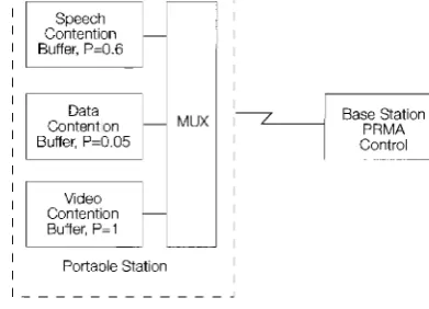
15 dB (PRMA) is invoked in order to multiplex graphics,tion. Apart from carrying out this function the PRMA multiplexer facilitates a more efficient exploitation of the transmission medium by allocating packets on a flexible demand basis to the graphics, voice and video users. Since our video codec [IS] delivers a constant- rate 8 kbit/s stream, the video information is conveyed using regularly-spaced TDMA-packets. Hence no video delay and packet dropping is inflicted and no buf- fer memory is required. In contrast, human speech has bursty statistics and the proportion of active speech spurts is around [28], which can be exploited to support a number of additional speech users [26] or to accom- modate a mixture of speech and data users 1271.
The voice activity detector [I21 queues speech pack- ets for transmission to the BS and if the Portable Station (PS) gets permission to transmit, it reserves the time-slot for the duration of the current active speech spurt. If a passive speech spurt is detected, the time-slot is surren- dered and can be reserved by other speech, data or video users, who are becoming active. If, however, due to packet collisions a speech user cannot get a reservation within the maximum tolerable delay of about 30 ms, the validity of the current speech packet expires, since new speech packets may be awaiting transmission. Hence this initial packet must be dropped but the dropping probability must be kept below Pdrop = I % [26] in order to minimise the speech degradation. Fortunately this initial spurt clipping is hardly perceivable.
In contrast, graphical data packets cannot be dropped, but tolerate longer delays and can be allocated to slots, which are not reserved by speech users in the present frame. In our experiments all but one graphical data users were obeying a negative exponential packet gen- eration model, while one user transmitted graphical traces generated by a writing tablet.
A less than unity permission probability either allowed or disabled permission to contend during any particular slot for a reservation within the current PRMA frame. Wong and Goodman noted 1271 that it is advantageous to control data packet contentions on the basis of t h e fullness of t h e contention buffer. Specifically, contentions are disabled, until a certain number of packets awaits transmission, which reduces the probability of potential packet collisions due to the frequent transmission of short graphical data bursts. While speech communications stability can be defined as a dropping probability Pdrop < 1%, data transmission stability is specified in terms of maximum graphical data delay or buffer requirement. The PRMA packet multiplexer is depicted in Fig. 8, where we indicated in the Figure the required permission probability P used by the various speech, data and video users in order to satisfy their corresponding delay and packet dropping constraints, while maximising the multiplexer's throughput capacity. The key P R M A parameters, including these speech, video and data permission prob- abilities, are listed in Table 2 along with a range of other system features.
Speech
1
Icontention
-I
,1 Buffer, P=0.6
Data
Content~on MUX 7-1
Ba"p"REion
~
Buffer, P=0.05 Control
Portable Station I
[image:8.472.254.450.8.149.2]I I - - - J
Fig. 8
-
PRMA packet multiplexer.The previously described components of the system were simulated and amalgamated. The range of simula- tion conditions will be specified throughout the forth- coming three subsection, describing the FL-DCC graphi- cal codec performance, the PRMA multiplexer's perfor- mance and the overall system performance, respectively.
7.1. FL-DCC graphical codec performance
The performance of the proposed FL-DCC schemes was evaluated for a range of dynamographical source sig- nals, including an English script, a Chinese script, a draw- ing and a map using a coding ring of M = 8. Table l shows the associated coding rates produced by FL-DCC for b = 1 and b = 2 as well as by DCC along with the cor- responding theoretical coding rates. Both FL-DCC schemes achieve a lower coding rate than DCC. The cor- responding subjective quality is portrayed in Fig. 9 for two of the input signals previously used in Tablel. Observe that for b = 2 no subjective degradation can be seen and the degradation associated with b = 1 is also fairly low. This is due to the fact that the typical fuzzy granular error patterns inflicted by the b = 1 FL-DCC scheme, when a straight line section is approximated by a zig-rag pattern, can be detected and smoothed by the decoder.
7.2. Multimedia PRMA performance
Fig. 9
-
Decoded information for FL-DCC with b = 1 (bottom), b = 2 (centre) and DCC (lop)traffic throughput capacity. This would have the disad- vantage that if suddenly a speech user wanted to acti- vate the video mode, helshe would have to wait for a TDMA-slot to become available.
Having allocated the TDMA video-slots, the remaining nine slots were offered to mixed speech and graphical data users. We found that in this scenario the optimum speech and graphical data permission probabilities were 0.6 and 0.05, respectively. The significantly lower data permission probability ensures that the delay-sensitive voice packets are not colliding with and delayed by agres- sively contending graphical data packets, which can more readily tolerate slight delays than interactive speech pack- ets. These delay issues will be portrayed in Fig. 10. The total traffic carrying capacity of the PRMA n~ultiplexer can be expressed in a variety of ways in terms of the number of speech, video and data users supported, which is typically related to the system stability limit. In our system stability was defined for speech users as a packet dropping probability of
PdmP
< I%, and for graphical data users as a maximum data buffer length of 100 packets, each delivering a 146 symbol packet. The total maximum storage required was then 100x
146x
418 = 7.3 kbytes. The PRMA multiplexer's efficiency can be quantified in terms of the slot occupancy, which ideally should be asclose to 1I)O% as possible, but this requirement contra- dicts to maintaining stability. In other words, the slot occupancy can be only increased at the cost of increased speech packet dropping probability or data packet delay and buffer length. In order to limit the variety of traffic loading scenarios under which the system's capacity is studied, similarly to the number of videophone users, we stipulated the number of graphical data users as nine. This assumption follows the argument that the penetration of new video and graphical services is expected to be lower than that of the more established voice services.
The system's traffic loading was varied by adjusting the data transnlission rate between 0.5 and 4 kbitfs in steps of 0.5 kbitls using negative exponential packet ani- val distribution and by setting the number of speech user- sto 9, 12, 13 and 14, who were generating speech spurts according to Brady's model [28]. Again, following Wong and Goodman [27], the minimum number of graphical data packets in the contention buffer to enable data con- tention was set to two, which slightly increased the mean data delay, but significantly reduced the chance of packet collision and dropping, while reducing the speech packet delay. The corresponding results are displayed in Figs. 10 - 12 for the mean data delay. maximum buffer size and slot occupancy, respectively,which were derived for a
\ . ' $ ' " "
. , ' . " . " . , , ' . . ' .,, , . . . . ' , . . , ' . I . ..., . . . . . , . . ' . .. . , . . . . .
.
., > . . ,~ " . . . . . , . . . 6 e
.
." . . . ". , . > . . . & . , . . . . . . ' ' . . > . . * . . . , . ' . " . . z . . ' " "
.
" . " r " . .~ . . . . , , , I , , . . , . . . I r . , . , . , . rr,)r - . . . " , , . " " I_
Data Delay (rns) 2500
1 2 3
Data Rate (kbiVs)
Fig. 10
-
Graphical data buffer sizc vcrsus data ratc for various num- ber of speech users using 16QAM.200 s duration communications session, transmitting 104 PRMA frames. As expected, the minimum mean data delay and required buffer size are maintained under light- ly loaded tele-traffic conditions. Observe from these Figures that when supporting nine 8 kbit/s video and nine 0.5 kbit/s graphical data users as well as a maximum of 14 8 kbit/s speech users, the mean data delay is less than about 600 ms and the required buffer size is below about 30 packets. Explicitly, due to speech burstyness and with the advent of voice activity detection and PRMA, the system can support up to 5 additional speech users with a dropping probability around 1 % plus nine 1 kbit/s graphi- cal users. This corresponds to a system capacity improve- ment of 5 x 8
+
9 x 1 = 49 kbit/s, or a relative capacity increase of 4949 x 8) = 68% over TDMA.Upon interpreting Figs. 10 - 12 from a different angle, if only 9 simultaneous voice communications are con- ducted along with the previously stipulated 9 video and data sessions, the packet dropping probability is virtually zero and both the data delay and the buffer size curves are rather flat up to a maximum data rate of about 3.5 kbit/s. At a rate of 3.5 kbit/s the stipulated graphical data stabil- ity limit of a buffer size of 100 packets is reached. The mean data delay becorrles about 200 rns. The data delay and buffer size curves of Figs. 10 and I I become more steep, if more than 9 speech users must be accornmodat-
Buffer Size (Packets) 400
14 Users 9 Users
7
+Data Rate (kbit/s)
Fig. 11 - Graphical data delay versus data rate for various number 01
speech users using 16QAM.
I
0 1 2 3 4
Data Rate (kbit/s)
Fig. 12
-
Slot occupancy versus data rate performance for various numbcr of speech users using 1 hQAhl.ed, since the interactive speech users enjoy a higher con- tention probability. Note in Fig. 12 that the slot occupan- cy defined as the proportion of slots occupied by packets is below 80% in all the above stable scenarios. Again, apart from its multiplexing function, the benefit of PRMA was that due to speech burstyness we could provide an extra 3.5 kbitls data channel for each of the nine speechlvideo users, which was equivalent to a channel capacity gain of 9 x 3.5 = 3 1.5 kbit/s. Relating this gain to the speech source rate of 9 x 8 = 72 kbit/s a relative chan- nel capacity gain of 31.5172 = 44% is achieved. This is lower than the capacity gain of the more heavily loaded 14-user scenario, where the higher traffic loading exhibit- ed itself in an increased packet dropping probability of about 1%. These findings are also reflected by the slot occupancy curves of Fig. 12. Let us now focus our atten- tion on the robustness aspects of the proposed graphical transceiver, when used over various wireless channels.
7.3. Robustness issues
Our experimental channel conditions were based on a worst-case Rayleigh-fading scenario using a propaga- tion frequency of 1.9 GHz, signalling rate of 133 kBd and vehicular speed of 30 mph. For reasons of space economy no modem BER versus channel SNR curves are plotted here, instead the overall system robustness will be characterised in Figs. 13 - 16. The graphical rep- resentation quality was evaluated in terms of both the mean squared error (mse) and the Peak Signal to Noise Ratio (PSNR). In analogy to the PSNR in image pro- cessing, the graphical PSNR was defined as the ratio of the maximum possible spatial deviation 'energy' to the coding error 'energy'. When using a resolution of 640 x 480 pixels, the maximum spatial deviation energy is 6402
+
4802 = 640 000, corresponding to a maximum diagonal spatial deviation of 800 pixels. The lossy cod- ing energy was measured as the mean squared value of the pixel-to-pixel spatial distance between the original graphical input and the FL-DCC graphical output. For perfect channel conditions the b = 1 and b = 2 FL-DCC codec had PSNR values of 49.47 and 59.47 dB, respec- [image:10.522.301.503.33.183.2] [image:10.522.60.268.35.184.2] [image:10.522.60.266.557.703.2]Channel SNR (DB) Channel SNR (DB)
Fig. 13
- Graphical PSNR versus channel SNR performance of the
b = Fig. 15- Graphical PSNR versus channel SNR performance of the
b =1 bil FL-DCCl16QAM mode of operation over various channels. I bit FL-DCCl4QAM mode of operation over various channels.
tively. As we showed in Fig. 9, the subjective effects of a 10 dB PSNR degradation due to using b = 1 instead of
P b = 2 are not severe in terms of readability.
The system's robustness was characterised in Figs. 13 -
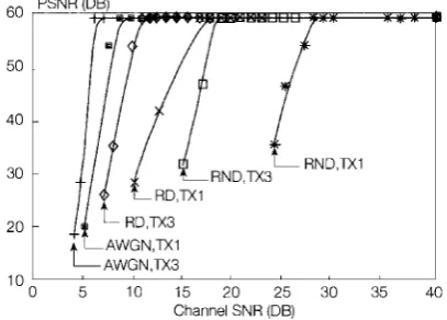
16 upon transmitting the handwriting sequence of Fig. 9 ten times, in order to ensure the statistical soundness of the graphical quality investigations. The best-case propa- gation scenario was encountering the stationary Additive White Gaussian Noise (AWGN) channel. The more bandwidth-efficient but less robust 16QAM mode of operation is characterised by Fig. 13. Observe that trans- missions over Rayleigh channels with diversity (RD) and with no diversity (RND) are portrayed using both one (TX1) and three (TX3) transmission attempts, in order to improve the system's robustness. Two-branch selection diversity using two independent Rayleigh channels was studied in conjunction with various selection criteria and we found that using the channel with the minimum phase shift between pilots slightly outperformed the maximum energy criterion. Similarly, over AWGN channels one or three transmission attempts were invoked.
As seen in Figs. 13 and 14 in case of the 16QAM mode, over AWGN channels the required channel SNR for unimpaired graphical communications is around 11 dB with ARQ and 12 dB without ARQ. This marginal improvement is attributable to the fact that the AWGN
PSNR DB
[image:11.574.297.508.38.183.2]' " 0 5 10 15 20 25 30 35 40 Channel SNR (DB)
Fig. 14
-
Graphical PSNR versus channel SNR performance of the b2 bit FL-DCCl16QAM mode of operation over various channels.
channel exhibits always a fairly constant bit error rate (BER) and hence during re-transmission attempts the chances of successful transmissions are only marginally improved. In contrast, over Rayleigh channels the received signal has a high probability of emerging from a deep fade by the time the packet is re-transmitted. This is the reason for the significantly improved robustness of the ARQ-assisted Rayleigh scenarios of Figs. 13 and 14. Specifically, with diversity the ARQ attempts reduced the required channel SNR by about 5 dB to around 15 dB, while without diversity an even higher 10-12 dB ARQ gain is experienced. When using the b = 2 bit FL-DCC scheme, Fig, 14 shows that the error-free PSNR was increased to nearly 60 dB, while the system's robustness against channel errors and the associated "corner SNR" values remained unchanged.
Fig. 15 demonstrates that when the more robust 4QAM mode was invoked, over AWGN channels SNR values of 5 and 8 dB were necessitated by the ARQ- aided TX3 scheme and the non-ARQ assisted T X l systems, respectively. The diversity-assisted RD, TX3 and RD, TX1 systems required a minimum SNR of about 10 and 17 dB for unimpaired graphical communi- cations, which had to be increased to 20 and 27 dB without diversity. Clearly. both the ARQ- and diversity- assistance played a crucial role in terms of improving
Fig. 16 - Graphical PSNR versus channel SNK performance of the h =
2 bit FZ-DCCl4QAM mode of operation over various channels. 20
Vol. 8. No. 3 May - June 1997 28 1
-
AWGN,TX3
l o o
j
10 1'5 2'0 253b
3'5 40 [image:11.574.64.268.556.703.2] [image:11.574.303.507.557.703.2]4,G
i ~ > " ~ ~ L t t ~ y~dwn
544 "7CIfi&
Cmlm~,~d ~ i $ r ~ p , ~ JetR
d
'I" I644 h ~ A q . j & r * ~ J W Y k f . ~
Rdi&pdL,if&ra4
o n ~ ~ ~7
J ~ ~ , i q/'
[image:12.472.90.376.10.326.2]over
&ispLns/uel*hm,
t + f q , ~ r 4 / o J ~ ~ ~ ~ .Fig. 17
-
Subjective effects of transmission errors for the b = 1 16QAM, RD, TX3 scheme for PSNK value5 of (left to right, top to bottom) 49.47,42.57,37.42, 32.01, 27.58 and 21.74 dB. respectively.the system's robustness. The same tendencies can be noted in Fig. 16 as regards to the b = 2 bit FL-DCC scheme. When using the lossless b = 3 bit FL-DCC or the conventional DCC scheme, the graphical PSNR becomes infinite. hence the corresponding PSNR versus channel SNR curves cannot be plotted. However, the transceiver's performance predetermines the minimum channel SNR values required for unimpaired graphical quality, which are about the same as for the above schemes. We note furthermore that since each packet commences with a pen-down code, the system can switch between the 4 and 16QAM modes arbitrarily fre- quently without any objectionable perceptual quality degradation or graphical switching transients.
The subjective effects of channel errors are demon- strated by Fig. 17 in case of the diversity- and ARQ assisted Rayleigh 16QAM, FL-DCC b = 1 scenario, where the graphical PSNR was gradually reduced from the error-free 49.47 dB at the top left hand corner to 42.57, 37.42, 32.01, 27.58 and 21.74 dB at the bottom right hand corner, respectively. Here we quoted the PSNR values, rather than the channel SNR values, since the associated graphical quality can be ensured by various system configuration modes under different channel con- ditions. The corresponding channel SNRs for the various system configuration modes can be inferred from the intercept points of the horizontal line corresponding to a particular PSNR value in Figs. 13 - 16. Note that when
the channel BER becomes high and hence the PSNR is degraded by more than about 5 dB, the graphical artifacts become rather objectionable. In this case it is better to disable the decoder's output by exploiting the error detec- tion capability of the BCH decoder.
channels, respectively. The system's robustness was improved and its tele-traffic capacity dropped, when 4QAM was invoked. Further key system features are summarised in Table 2. Our future work is targeted at studying various adaptive modem reconfiguration algo- rithms and improving the bit rate, resolution and robust- ness balance of the system.
Acknowledgement
The financial support of the EPSRC, UK in the framework of the research contract GRlK74043 is gratefully acknowledged.
Manuscript received on January 24, 1996.
[ I ] D. L. Neuhoff, K. G. Castor: A rate and distortzorr analysis of chain codes for line drawings. "IEEE Tran. Information Theory", Vol. IT-31, Jan. 1985, p. 53-68.
121 K. Liu, R. Prasad: Perforn7ance analysis o f r l ~ ~ e r e n t i a l chain codbia. "Eurooean Transaction on Telecommunications and ~ e l a t c d ~ e c h n d l o ~ y " , Vol. 3, Jul-Aug. 1992, p. 323-330 [3] A. B. Johannessen, R. Prasad, N. B. J. Weyland, J. H. Bons:
Coding eficiency of multiring differential chain coding. "IEE Proceedings", Part I, Vol. 139, April 1992, p. 224-232. [4] R. Prasad, J. W. Vivien, J. H. Bons, J. C. Ambak: Relative vec-
tor probabilities in diffrrentiul chain coded line drawings. Proc. of IEEE Pacific Rim Conference on Comms., Computers and Signal Processing, Victoria, Canada, June 1989, p 138-142. [5] R. Prasad, P. A. D. Spaargaren, J. H. Bons: Teletext reception in
a mobile channel for a broudcust tele-information system.
"IEEE Tr. on VT.", Vol. 42, No. 4, Nov. 1993, p 535-545. [6] Advanced Communications Technologies and Services,
Workplan, DCXIII-B-RA946043-WP, 1994.
[7] M. C. W. Van Bull: Hybrid D-PCM, a combination of PCM und DPCM. "IEEE Tr. on Comrns.", Vol. Com-26, March 1978, p 362-368.
[8] N. S. Jayant, P. Noll: Digitul coding uf wuv~forms. Prentice- HaI1. 1984.
[9] D. Greenwood, L. Hanzo: Mobiie radio channels. Chapter 2 In: (R. Sleele Ed.), Mobile Radio Communicalions, IEEE Press- Pentech Press, London, 1992, p 92-185.
[I01 R. A. Salami, L. Hanzo, et al: Speech Coding. Chapter 3 In: (R. Steele Ed.), Mobile Radio Communications, IEEE Press- Pentech Press, London, 1992, p 186-346.
[ I l l K. H. H. Wong, L. H a n ~ o : Channel Coding. Chapter 4 In: (R. Steele Ed.), Mobile Radio Communications, IEEE Press- Pentech Press, London, 1992, p 347-489.
[I21 L. Hanzo, J. Stefanov: The Pan-European Digital Cellular Mobile Radio Svstem - known as GSM. Chanter 8 In: (R. Steele Ed.), Mobile Radio Communications, lEEE Press-Pentech Press, London, 1992, p 677-773.
11 31 W. T. Wcbb, L. Hanzo: Modern quadrature amplitude modula- tion: Principles and applicatiorrs for fired and wireless channels.
"IEEE Press-Pentech Press", ISBN 0-7273-1 701 -6, 1994, p 557.
[14] L. Hanzo, J.P. Woodard: An intelligent multimode voice conlmu- nications system for indoors communications. "IEEE Tr. on Veh. Technology", Vol. 44. No. 4, Nov. 1995, p 735-749. 1151 L. Hani~o, .I. Streit: Adaptive low-rate wireless videophone
schemes. "IEEE Tr. on C i r c u i t s , S y s t c m s and Video Tcchnology", Vol. 5, No. 4, Aug. 1995, p 305-319.
[I 61 J. P. Woodard: Digital coding of speech using code excited line- a r prediction. Phd. Thesis, Dcpt. of Elcctr. Univ. of Southampton, UK. Nov. 1995.
[I71 J. Torrancc, L. Hanzo: A comparative study of pilot symbol assissted modem schemes. Proc. of IEE RRAS'95 Conference, Bath, UK, Conf. Public. No. 415, 26-28 Sept. 1995, p 36-41. [I81 E. Biglieri, M. Luise: Coded modulation and bandwidth-efji-
cient transmission. Proc. of the Fitth Tirrenia Intern. Workshop, 8-12 Sept. 1991, EIsevier, Netherlands, 1992.
1191 IEEE Communications Magazine, Special Issue on Coded Modulation, Vol 29, No 12, Dec. 1991.
[201 L.F. Wei: Coded modrrlatiorr with unequal error protection.
"IEEE Tr. on Comms.", Vol. 41. No. 10, Oct. 1993, p 1439-1450.
[21] C. Berrou, P. Thitimajshima: Near shannon limit error-correc- tion coding and decoding: T~rrbo-codes. In Proceedings of the International Conference on Communications (ICC'93), (Geneva), May 1993, p. 1064-1070.
[22] J. Hagenauer, E. Offer, L. Papke: Iterative decoding of binary block and convolutional codes. "IEEE Transactions on Information Theory", Vol. 42, 1996, p. 429-445.
1231 .I. K. Cavers: An analysis ofpilot .symbol assisted modulation for rayleigh fading channels. "IEEE Tr. on V T , Vol. 40: No 4, Nov. 1991, p 686-693.
[24] M. L. Moher, J. H. Lodge: TCMP - a modulation and coding strutegy for riciun ,fatling chunnels. "IEEE J. Select. Areas Commun.". Vo1.7, Dec. 1989, p. 1347-1355.
[251 S. Sampei, T. Sunaga: Rayleigh fading compensation method for 16-QAM in digital land mobile raciio channels. Proc. IEEE Veh. Technol. Conf., San Francisco, CA, May 1989, p. 640-646. [26] D. .I. Goodman, S. X. Wei: Efficiency of packet reservation rrrul-
tiple access. "IEEE Transactions on Vehicular Technology". Vo1.40, No. 1, Febr. 1991, p. 170-176.
[27] W. Wong, D. Goodman: A packet reservation uccess protocol for integrated speech and data transmission. "Proc. o l the IEE,
Part-I", Vol 139, No 6, Dec. 1992, p 607-61 3.
[28] P. T. Brady: A model for generating on-off speech patterns in two-way conversation. "Bell System Technical Journal", Vol. 48, No. 7, September, 1969, p. 2445-2472.