10
©IJRASET: All Rights are Reserved
Application of Intelligent Control in Load
frequency Control of Multi Area Power System
Hari Singh Moond1, Ashish Jaiswal2
1, 2
Electrical And Electronics Department, Rajasthan Institute Of Engineering And Technology
Abstract: The aim of this study is to present healthy load frequency control (LFC) for multi area hybrid power system. Multi area power system is not supply steady electric power output and many times cause disturb between demand and supply. This paper shows the use of Proportional-Integral (PI) Controller with control the variation in tie-line power and frequency variation of a three area thermal-hydro power system due to 1% disturbances in loading. MATLAB SIMULINK software is used for designing system. The system is first analyzed for single PI controller then response of the system like settling time and oscillations are very high that is not satisfactory result. After that we analyzed the response of the system with artificial neural network (ANN). The comparative study between PI and ANN controllers the result shows that ANN controller performance better than PI controller and also improve the oscillations and settling time. Therefore system becomes extra stable and reliable.
Keywords: LFC, PI, Artificial Neural Network Automatic Generation Control.
I. INTRODUCTION
Frequency variation is one of the most essential factor of power system Network. It confirms quality of power supply is reliable and sufficient. Since the theory of Load frequency control is directly related to the above mentioned parameter it plays a substantial role in transient stability of the power system. Load frequency control is very critical aspect in the operation of power system ensuring the good and reliable supply of power in sufficient quantity to the consumer. An unbalanced system caused by the power mismatch between load and generating side results in frequency aberration. The permanent damage to electrical equipment, degradation in load performance, power transmission line overvoltage and triggering of the protected devices are particular negative effects of this peculiarity.
The continuous growth in size and complexity of interconnected power systems, along with both area frequency and tie-line power interchange. The main purpose of load frequency control (LFC) is to sustain frequency of the system under prescribed limits and check the fluctuations on tie-line loading in case of multi area power system. Past year Automatic generation control (AGC) system specifies an applicable way to hold a control over the frequency and tie line power flow. Different methods have been suggested for Load Frequency Control. The best common technique which is commonly used around world since few years is based Proportional Integral (PI) controllers, but with exponentially increasing electricity market essential for more progressive control techniques arises for correct effective of large numbers of interconnected multi area generating units. The control of load frequency and the operational aspect of automatic generation control for a multi area hybrid interconnected power system In the large interconnected power system the risk of network failure is increased many times as the system frequency is related to Active power. The two predictable controllers are based on the theories of PI and artificial neural network which is being tested on the three area interconnected hybrid power system which embraces thermal power plant with and without re-heater and hydro power plant with different loading. As it is apparent that frequency control is laggard control when paralleled against voltage control so it is necessary to reduce the transient time in load frequency control to boost the overall power system performance. Both the proposed controller is discussed in details with respect to their working and implementation in interconnected power system network completely replacing the present day PI controller. An iterative linear estimate built matrix algorithm is framed to linearize the system. Modern control technique based on network Fuzzy Logic based Controller (FLC),Artificial Neural Network (ANN), and genetic algorithm crafted are assessed for LFC problem. Yet bountiful exertion have been made for optimizing predictable LFC but very less exertion for designing intelligent controller for multi area power system.
This paper shows the two different controllers designing method falls in same groups one of them is PI controller approach with optimum control and other controller is ANN made on back prorogation process. In this process trained to adjust the non-linear control situation and provide acceptable increase complete frequency variation & tie line power flow.
11
©IJRASET: All Rights are Reserved
II. SYSTEMINVESTIGATION
A. Three Area System
A three area system consists of three single area power systems, connected through a link called tie-line. A tie line is the interconnection between each area for an uninterrupted power flow between each other. Every area is denoted by equivalent generator and load power flow. Typical three area interconnected power system is shown in Fig 1. where area 1 has three generating station and two load station, area 2 has two generating unit and a single load and area 3 has two generating unit and two load centre.
Fig.1. Three area interconnected power system with tie-line
In a typical arrangement for load frequency control of multi area system contains the basic component like turbine, generator, speed governor, and controller. The controller ordinarily used in the power system industry is Proportional-Integral controller.
B. Modelling of three area power system in SIMULINK with ANN and PI controller
The schematic of interconnected multi area system with and without re heater and hydropower system is illustrated in Fig. 2. The model has been considered for demonstration and investigation of frequency deviation in different cases. Effect of control techniques essential for selected to improve system dynamic performance and stability.
Fig.2. Simulation model for three area power system using PI controller
12
©IJRASET: All Rights are Reserved
In MATLAB the neural network tool can be accessed by using Neural Network tool box in Simulink library. After generating the data for input and target data we create a Simulink block to be used in simulation. The controller used for this purpose is Reference model neural network where first plant identification needs to be done after that reference model training is possible.
Fig.3.Simulation model for three area power system using Neural Network
III. CONTROLLERDESIGNMETHODOLOGY
Artificial neural networks(ANN) have a ability to find out and change as of given sample information below unpredictable control. These reasonably reconciling apply is compatible for nonlinear power systems to project a strong LFC for an outsized range of interconnected power systems. The expected ANN controller is stranded on victimization the method of back propagation algorithmic rule. space management error is electoral to be present input to ANN management and output is ready to right control the rotary engine governor [6]. It usages a two layer design that is show in Fig. 4, carries with it 10 nerve cell. every nerve cell has its input increased to its equivalent linking weight and additional permits to subsequent layers nerve cell, so the ultimate output from network is in step consistent with providing target value.
13
©IJRASET: All Rights are Reserved
ANN controller is trained offline in batch mode done the information gained from the up to date PI controller in Figure 3 Artificial Neural Networks Modified neural networks is made by MATLAB neural network tools with instigation functions TRAINGDX having knowledge function LEARNGDM & transfer function using LOGSIG. The generated networks are trained with 1 era till recession value used for training data touches near to 1.Modified neural network is formed victimization MATLAB neural networks
tools by initiation perform TRAINGDX having book learning perform LEARNGDM & therefore the transferal perform using LOGSIG. The generated network is trained victimization one epoch till regression price for coaching information reaches terribly getting ready to one.
IV. SIMULATIONANDRESULTANALYSIS
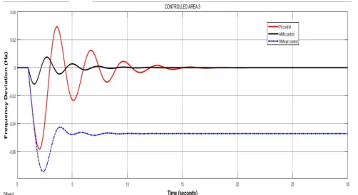
[image:4.612.182.431.404.528.2]three area closed loop system are used for Simulation of PI and ANN controller are carry out on equal loading condition that is variation of step load is 1% arise at 1 sec and all other parameter is constant. The waveforms from fig 5 to fig 7 show frequency variation for PI and ANN for all three area respectively. It is find the average of settlingtime is approximately ten seconds.
[image:4.612.183.434.570.707.2]Fig. 5. ∆f1 vs Time waveform for 1% load deviation (area 1 frequency deviation with respect to time without controller,with PI controller and with ANN controller)
Fig. 6. ∆f2 vs Time waveform for 1% load deviation (area 2 frequency deviation with respect to time without controller,with PI
controller and with ANN controller)
Fig. 7. ∆f3 vs Time waveform for 1% load deviation (area 3 frequency deviation with respect to time without controller,with PI
14
[image:5.612.194.439.77.241.2]©IJRASET: All Rights are Reserved
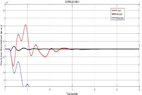
[image:5.612.202.432.281.430.2]Fig. 8. ∆Ptie vs Time waveform for 1% load deviation (tie-line power variation among area1 & area2 with respect to time without controller,with PI controller and with ANN controller)
Fig. 9. ∆Ptie vs Time waveform for 1% load deviation (tie-line power variation among area2 & area3 with respect to time without controller,with PI controller and with ANN controller)
Fig. 10. ∆Ptie vs Time waveform for 1% load deviation (tie-line power variation among area 3 & area1 with respect to time without controller,with PI controller and with ANN controller)
[image:5.612.202.426.474.647.2]15
©IJRASET: All Rights are Reserved
Table I: Comparison Of Settling Time
Controlle r ∆f Area 1(sec ) ∆f Area 2(sec ) ∆f Area 3 (sec)
∆Ptie Area 1(sec
)
∆Ptie Area 2(sec)
∆Ptie Area 3
(sec)
PI 13 15 18 19 19 21
ANN 7 8 10 9 8 8
For LFC controller work is to reduce the frequency deviation and maintain the tie line power at desired level. The controller which is centered on the PID controller and other side neural network based controller used the concept of back propagation algorithm. Comparative study of settling time is shown in Table I for tie line power deviation and frequency deviation. The ANN controller is better dynamic response then PI controller.
V. CONCLUSION
This research presents the essential analysis between the two controller. Artificial Neural Network (ANN), technique is artificial neural network. Controllers are Designed for multi area hybrids power system with the different loading condition in every area and controllers reached steady state error to zero. the controller property is supports to theo overall system to increase fast even when operating condition is highly nonlinear. The ANN controller gives instantaneous time response because of the learning process is memory based. Compare to PI controller, ANN controller is shown to be extra effective due to the learning process is more advanced that it embraces. The all comparative MATLAB simulation result of both the controller indicate Artificial Neural Network (ANN) controller is faster and have much less troughs and peaks all through the transient time.
REFERENCES
[1] P. Kundur, Power System Stability and Control, Mc-Graw Hill, 2007.
[2] H. Bevrani, P. R. Daneshmand, “Fuzzy Logic-Based Load- Frequency Control Concerning High Penetration of Wind Turbines”, IEEE Systems Journal 2012, pp. 173-180.
[3] H. Bevrani, Y. Mitani, and K. Tsuji, “Robust decentralized load- frequency control using an iterative linear matrix inequalities algorithm”, Proc. Inst. Electr. Eng. Gener. Transm. Distrib., vol.151, no.3, May 2004.
[4] X. J. Liu and J. W. Zhang, “CPS compliant fuzzy neural network load frequency control”, American Control Conference, St. Louis, 2009, pp. 2755-2760. Y.
[5] Deepak Kumar Lal,Ajit Kumar Barisal,“ Frequency Control of AC Microgrid Interconnected Thermal Power System”, OP Conf. Series: Materials Science and Engineering 225 (2017).
[6] S. Sönmez, S. Ayasun and C. O. Nwankpa, “An Exact Method for Computing Delay Margin for Stability of Load Frequency Control Systems With Constant Communication Delays”, IEEE Transactions on Power Systems, vol. 31, no. 1, pp. 370-377, Jan. 2016.
[7] H. Shayeghi, H. A. Shayanfar, “Application of ANN Technique Based on Mu-synthesis to Load Frequency Control of Interconnected Power System”, Elect. Power Energy Syst., pp.503–11, 2006.
[8] N. Chuang, “Robust H∞ load-frequency control in interconnected power systems”, IET Control Theory & Applications, vol. 10, no. 1, pp. 67-75, 2016.
[9] S. Wen, X. Yu, Z. Zeng and J. Wang, “Event-Triggering Load Frequency Control for Multiarea Power Systems With Communication Delays”, IEEE Transactions on Industrial Electronics, vol. 63, no. 2, pp. 1308-1317, Feb. 2016.
[10] Y. Zhang, X. Liu and B. Qu, “Distributed model predictive load frequency control of multi-area power system with DFIGs”, IEEE/CAA Journal of Automatica Sinica, vol. 4, no. 1, pp. 125-135, Jan. 2017.
[11] B. Polajžer, R. Brezovnik and J. Ritonja, “Evaluation of Load Frequency Control Performance Based on Standard Deviational Ellipses”, IEEE Transactions on Power Systems, vol. 32, no. 3, pp. 2296-2304, 2017.
Appendix
The parameters of the multi area power system are shown as:
Tgk= Time constant of governor kth area in sec.
Ttk= Time constant turbine of kth area in sec.
Kpk= Power system gain of kth area
Tpk=Power system time constant of kth area [sec]
Rk = Speed Regulation of governor in kth area in Hz/puMw B1=B2=Constants which specify the frequency bias for the line load bi- as control