Impact of distributed PV generation on relay coordination
and power quality
AKMAL, Muhammad <http://orcid.org/0000-0002-3498-4146>, AL-NAEMI,
Faris, IQBAL, Nusrat, AL-TARABSHEH, Anas and MEEGAHAPOLA, Lasantha
Available from Sheffield Hallam University Research Archive (SHURA) at:
http://shura.shu.ac.uk/25096/
This document is the author deposited version. You are advised to consult the
publisher's version if you wish to cite from it.
Published version
AKMAL, Muhammad, AL-NAEMI, Faris, IQBAL, Nusrat, AL-TARABSHEH, Anas and
MEEGAHAPOLA, Lasantha (2019). Impact of distributed PV generation on relay
coordination and power quality. In: 2019 IEEE Milan Power Tech. IEEE.
Copyright and re-use policy
See
http://shura.shu.ac.uk/information.html
Sheffield Hallam University Research Archive
Impact of Distributed PV Generation on Relay
Coordination and Power Quality
Muhammad Akmal, Faris Al-Naemi Nusrat Iqbal, Anas Al-Tarabsheh
Lasantha Meegahapola
Electrical Power and RenewableEnergy Systems Research Group Electrical and Computer Engineering Department Electrical and Biomedical Engineering Department Sheffield Hallam University Abu Dhabi University RMIT University Sheffield, S1 1WB, United Kingdom Abu Dhabi, United Arab Emirates Melbourne, Australia
[email protected] [email protected] [email protected]
Abstract— Distributed generation (DG) has gained popularity among electricity end users who are determined to contribute to a cleaner environment by conforming to green and sustainable energy sources for various daily needs. The power system impact of such trends (e.g. roof-top solar-PV) need thorough investigation, such as impact on fault current levels on the distribution network. Varying fault current levels could adversely affect the operation of protection relays, which may lead to localized blackouts. Therefore, it is imperative to avoid localised blackouts due to mal-operation of protective relays under high penetration of DGs in distribution network. The focus of this research is to study the importance and implications of protective relays and over-current protection in the presence of distributed generation; where the impact of distributed generation on distribution network is identified. Relay coordination is observed to determine their operation characteristics to avoid mal-operation with the presence of DGs (e.g. solar-PV). This paper uses the UK generic distribution network model to simulate different scenarios in DIgSILENT Power Factory. The resulting power quality measures, such as voltage levels, short-circuit current levels and frequency are presented and discussed in the paper. The research highlights that small-scale DG penetration allows for existing protection infrastructure to continue operation and expensive upgrades for overall network are not required as fault levels remain the same.
Index Terms- Distributed generation, over-current protection, power systems simulation, relay coordination, power quality.
I. INTRODUCTION
The emergence of renewable distributed generation (DG) can be related to the need for cost reduction in power transmission and distribution and diversify the power sources while empowering the use of clean energy combined with technological innovations in power electronics [1]. The DG growth has accelerated globally due to national and international policies on increasing energy produced from renewables to decrease the effects of greenhouse gas emission on global warming, and deregulation of many energy markets [2]-[3]; thus, DGs are less damaging to the environment, and having simple installation process allows for greater reliability by being extremely efficient [4]. The majority of DGs are sourced from photovoltaic (PV) panels,
and wind turbines, and are connected to the distribution network.
Distributed generation comprises of power generating units that use some of the latest technological innovations to produce few kilowatts to megawatts of power while being quite compact. DGs are usually owned by individuals and placed near electrical loads; independent power producers and electric utilities also own DGs [5]. DGs have advantages such as being environmentally friendly, reduction of on-peak operating cost, and potential increase of service quality to the customer. Additionally, it is easier to place and install DG, as they are available in modular units; thus, leading to less time for construction and lower capital costs [3]. The major issues in the integration of distributed generation systems are; frequency stabilization issues, voltage stabilization issues, intermittency of the renewables, power quality issues [6], and its negative effect on the distribution system protection such a relay mal-operation. The addition of DG to the system causes changes in the magnitude and direction of the power flow, as well as short-circuits current during fault conditions. The severity of the disturbance in the system depends on the size, location, the DG technology type, and the way they are connected to the distribution network [5].
This study investigates the impact of high penetration of DGs on existing protection schemes. The UK generic distribution network is used for simulations, whereby relays are configured, and DGs are added, and their performance is tested under fault conditions. This paper also elaborates on the way distributed generation affects the distribution system and their impact on fault current levels. The novelty of the work is mainly assessing the impact in a real-time dynamic simulation.
The paper is organised as follows: Section II covers related literature on protection and DGs, Section III describes the test network system used for simulations, Section IV discusses the methodology, Section V presents the results, and Section VI summarizes the study conclusions.
II. LITERATURE REVIEW
(MV) and low voltage (LV) feeders supplying the customers. Therefore, voltage regulation and any disturbances in the system are easily taken care of unlike when DG is involved. [2]. DG can affect the power quality and other aspects of the network such as reversal of power flow, variations in voltages, causing harmonic pollution, unwanted island operations, and nuisance trips [1]. Thus, the interrupted nature of DG means that system protection with traditional methods is inadequate [7]. Additionally, as more DGs of greater power are incorporated in the system, changes can be noted in the power flow and predicted raise in fault-current levels requires existing protection devices to be changed or made more accommodating [8]. Protective relay coordination, which is present to quickly clear faults, may be disrupted due to the increase in fault current levels leading to a loss of coordination between relays and thus, equipment damage [9].
The type of DG installed influences the changes that can occur in a network. DG can either be rotating devices that are directly coupled to the network, or they may be static or rotating devices connected to the network through electronic converters. To elaborate, inverter-based DG is capable of voltage control while they affect harmonic levels of the system more than synchronous based DG. Moreover, protection coordination is significantly affected when there is directly coupled rotating DG incorporated in the network than DG interface through converters [3].
An important characteristic of a good protection coordination scheme is to isolate only the part of the system where the fault was detected so that other areas continue receiving the power supply. It is also imperative to design and coordinate protection systems in such a way that protection devices promptly react to the problem, and should it fail then a backup should be available. Overcurrent relays and fuses are enough for existing distribution systems, as they are mostly radial with unidirectional power flow. However, as DG would cause the bi-direction flow of power the complexity of the system also increases requiring the necessity for more sophisticated protection system and coordination [10].
Power system protection is an essential component of the distribution network, as continuous and optimum power is always desired. Protection systems monitor the network continuously to detect and clear any undesired event in the system so that equipment and people are not affected [11]. A protective relay can be defined as a complex electromechanical apparatus that can trip circuit breakers when a fault is detected by reacting to the operating conditions in the network. It is very important to have knowledge about fault characteristics, and tripping natures of protective relays. Also, essential is the fact that primary protection devices near the fault should react before the secondary ones further away thereby, ensuring that power flow to places away from the fault is not affected. Thus, time coordination between relay and circuit breaker is also very important. The main function of a protection system is to detect and remove a fault as soon as possible without damage to equipment [11]. Fault analysis involves the following two stages; firstly, identifying the maximum current a device can withstand and the point at which the switching device must trip, and secondly, the coordination between the protection
devices. It is understood that a surge in current level is the most obvious indicator of the existence of a fault; thus, over-current protection is commonly and extensively used [11]. Furthermore, the issues relating to relay coordination are still undergoing research and development [5]. Power quality issues have been discussed including harmonic modeling and operational impacts on power systems in [12] and 13].
This paper demonstrates the impact of DG on the existing distribution system, and the necessity for better protection systems by using DIgSILENT PowerFactory software tool as the main simulation platform. The DIgSILENT PowerFactory is an “all-in-one” software enabling the modelling of the system along with allowing for the addition of protection devices, and incorporation of applications like distributed generation in the network. DIgSILENT assists with a smooth assimilation of functionality with the management of all data in an easy to use environment [14].
III. TEST NETWORK
The UK generic distribution network (UKGDN) is used for this experimentation, and it is shown in Fig. 1. It consists of a 33/11.5 kV substation that supplies six 11 kV feeders which are then connected to eight 11/0.433 kV, 500 kVA transformers, and an equal number of 400 V busbars. Each 400 V substation serves 384 single-phase consumers through four radial feeders, each with 96 consumers in four clusters of 24, 8 per-phase. One feeder is modelled in detail, and the rest are treated as lumped loads [15]-16]. The external in-feed supplies 14,615.31 kW to the distribution network. The network evaluated by several distribution network operators can be considered as representative of urban /suburban UK distribution networks. Photovoltaic (PV) distributed generation (DG) are added as shown in Fig. 1 and they are brought into service when required by the simulation criteria. The net power provided by the PV systems is 60 kW which is to compensate the power lost during the transmission.
IV. METHODOLOGY
The purpose of this study is to observe fault current levels in the distribution network with and without DGs. Therefore, four scenarios outlined in Table 1 are considered for the investigation. Moreover, four photovoltaic DG are added to the end terminals of the feeder, namely terminal 1, 2, 3, 4 and one PV is added at terminal 17. They are each given an apparent power rating of 11.53 kW to make up for losses in the network. Furthermore, relay coordination during the short circuit events is tested. The short circuit events are detailed in Table 2. The relay model GE-Alstom KCGG 142-1A is used as over-current protection at three points in the radial network as described in Table 3. Additionally, the grading between each relay is set to 0.3 s. Finally, network is simulated for 10 seconds for each scenario in Table 1.
Table 1: The four scenarios simulated
Scenario Fault Photovoltaic DG
Figure 1: UK Generic Distribution Network modelled in DIgSILENT Power Factory
V. RESULTS AND DISCUSSION
A. Line currents from Load Flow Calculation
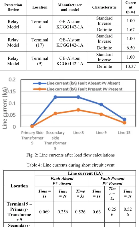
The line currents obtained after load flow calculations from the four scenarios are plotted and tabulated then presented in Fig. 2 and Table 4 respectively. Fig. 2 shows the line current during the two scenarios with and without PV, while Table 4 shows the line currents in the presence of faults at various locations, also with and without PV.
Table 2: The sequence and locations of the short circuit events
Event Terminal Time (s)
[image:4.612.329.545.633.697.2]B. Relay Coordination
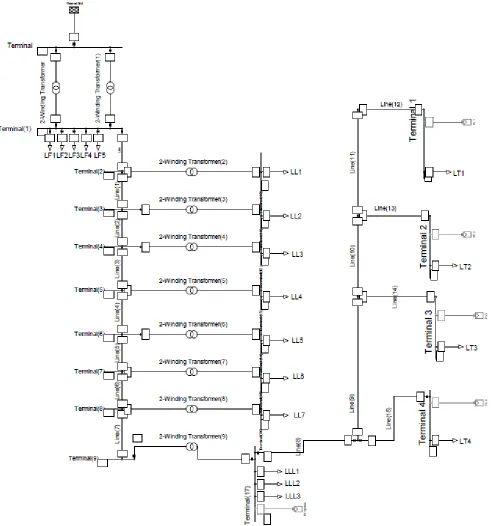
Fig. 3 presents the time over-current relay characteristic curves for the three relays used. The peak fault currents obtained, as shown in Table 4, are used to set the pickup current and operation time for the relays.
Table 3: The over current relay model descriptions and settings.
Protection
Device Location Manufacturer and model Characteristic
Curre nt (p.u.)
Relay Model
Terminal 4
GE-Alstom KCGG142-1A
Standard
Inverse 1.00 Definite 1.67 Relay
Model Terminal (17) KCGG142-1A GE-Alstom
Standard
Inverse 1.00 Definite 6.50 Relay
Model
Terminal (9)
GE-Alstom KCGG142-1A
Standard
[image:5.612.52.295.148.545.2]Inverse 1.00 Definite 13.37
Fig. 2: Line currents after load flow calculations Table 4: Line currents during short circuit event
The operation of each relay is tested in the absence of the DG, and the frequency, voltage and short circuit current are shown in Fig. 4. Fig. 4 (a) depicts the short circuit current level during the presence of the three faults and the absence of the DG. It is observed that the current level increases as it gets closer to the source and the time taken to clear the short circuit current is clearly seen. Fig. 4 (b) is the voltage profile during the occurrence of faults. A voltage drop could be noticed at the terminal where the fault occurs, while the voltages of the upstream terminals drop and then recovers.
[image:5.612.316.552.288.476.2]Fig. 4(c) shows the frequency of the system where it is noted that the frequency remains within an acceptable range.
Fig. 3: Alstom KCGG142-1A over current relay characteristic curves. Blue: Terminal 4, Red: Terminal 17, Green: Terminal 9
Fig. 4(a): Short circuit current level during faults without DG.
Fig. 4(b): Voltage profile of the terminals during fault without DG.
Location
Line current (kA) Fault Absent
PV Absent Fault Present PV Present Time =
1s Time = 2s Time = 3s Time = 1s Tim
e = 2s
Time = 3s Terminal 9 –
Primary- Transforme
r 9
0.069 0.256 0.526 0.66 0.256 0.526
Secondary- transformer
9
1.744 6.504 13.373 1.681 6.491 3.373
Line 8 1.744 6.5040 0 1.7 6.508 0
Line 9 0.077 0 0 0.037 0 0
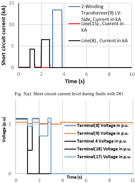
[image:5.612.324.546.509.693.2]The short-circuit levels, voltage and frequency with the presence of DG are shown in Fig. 5 (a), (b) and (c). The results appear to be very similar, since fault current contribution from the DG is minimal and like what is obtained without DG as shown in Table 5. Hence, the coordination between the relays is smooth in both the scenarios. The fault clearing times are noted in Table 5.
Fig. 4. (c): Frequency in the terminals during the fault without DG.
Fig. 5(a): Short circuit current level during faults with DG.
Fig. 5(b): Voltage profile of the terminals during fault with DG.
[image:6.612.325.552.64.217.2]Fig. 5. (c): Frequency in the terminals during the fault with DG. Table 5: Fault clearing time for the relays
Relay Location Fault Time (s) Fault Clearing Time (s)
Terminal 4 1 1.398 Terminal 17 2 2.734 Terminal 9 3 3.830
The results indicate that relay coordination is properly done in the presence of faults, as seen from fig. 4 (a), (b) and fig. 5 (a), (b). The short circuit current and voltage in the terminals drop to zero as soon as the relays operate. The relays take 0.398 s, 0.734 s, and 0.830 s to operate with a grading of 0.3 s, as the faults occur at 1 s, 2 s, and 3 s respectively. The frequency levels do not fluctuate much; however, compared to Fig. 4(c) the frequency in fig. 5(c) dips 0.005 Hz more during the fault. Moreover, comparing Fig. 4 (a), (b) and (c) with fig. 5 (a), (b) and (c) leads to the conclusion that small-scale DG has minimal contribution to fault current and hence, relay coordination parameters in such scenarios can be maintained as in a case where DGs are absent.
VI. CONCLUSION AND FUTURE WORK
[image:6.612.63.285.167.317.2] [image:6.612.317.557.248.342.2] [image:6.612.56.288.351.665.2] [image:6.612.57.288.353.492.2]requires no amendments for relay coordination parameters. Nevertheless, for a future study it is projected that large-scale DG penetration would require parameters of protective devices to be adjusted as frequency may fluctuate further and there can also be significant fault current contribution.
REFERENCES
[1] F. Belloni, C. Chiumeo, C. Gandolfi, and S. Pugliese. "Simulation model of a protection scheme for active distribution networks," in Proc.
2013, International Conference on Renewable Energies and Power
Quality (ICREPQ’13), Bilbao,Spain
[2] J. Barr, and R. Majumder, “Integration of Distributed Generation in the Volt/VAR Management System for Active Distribution Networks,”
IEEE Transactions on Smart Grid, vol. 6 Iss.2, pp.576-586, 2015
[3] P. S. Georgilakis, and N. D. Hatziargyriou. "Optimal distributed generation placement in power distribution networks: models, methods, and future research,"IEEE Transactions on Power systems, vol. 28, Iss. 3, pp. 3420-3428, 2013
[4] P. Basak, S. Chowdhury, S. H. nee-Dey, and S. P. Chowdhury, “A literature review on the integration of distributed energy resources in the perspective of control, protection and stability of microgrid,”
Renewable and Sustainable Energy Reviews, vol. 16 Iss. 8, pp.
5545-5556, 2012
[5] W. El-Khattam, and L. S. Sidhu. "Restoration of directional overcurrent relay coordination in distributed generation systems utilising fault current limiter,"IEEE Transactions on Power Delivery,vol. 23, no. 2, pp.576-585, 2008
[6] A. Khamis, H. Shareef, E. Bizkevelci, and T. Khatib "A review of islanding detection techniques for renewable distributed generation systems,"Renewable and Sustainable Energy Reviews, vol.28, pp.483-493. 2013
[7] M. Monadi, M. A. Zamani, J. I. Candela, A. Luna, and P. Rodriguez, “Protection of AC and DC distribution systems Embedding distributed energy resources: A comparative review and analysis,” Renewable and
Sustainable Energy Reviews, vol. 51, pp.1578-1593. 2015
[8] Y. Kim, H. C. Jo, and S. K. Joo. "Analysis of Impacts of Superconducting Fault Current Limiter (SFCL) Placement on Distributed Generation (DG) Expansion,"IEEE Transactions on Applied Superconductivity vol. 26, no. 4, pp.1-5, 2016
[9] S. K. De and P. Raja, “A study on relay coordination in a distribution system with distributed generation and hybrid SFCL,” IEEE AFRICON, pp. 1-6, 2013
[10] W. K. Najy, H. H. Zeineldin, and W.L. Woon. "Optimal protection coordination for microgrids with grid-connected and islanded capability,"IEEE Transactions on Industrial electronics, vol. 60, no. 4, pp. 1668-1677, 2013
[11] M. H. Hussain, S.R.A. Rahim and I. Musirin. "Optimal overcurrent relay coordination: a review,"Procedia Engineering, vol. 53, pp. 332-336, 2013
[12] R. A. Jabbar, S. A. Qureshi, M. Akmal, W. A. Qureshi, and A. Ahmad, “Practical analysis and mathematical modeling of harmonic distortions caused by electronic loads,” 7th IASTED Conf. on Power and Energy
Systems EuroPES, 2007
[13] R. A. Jabbar, M. Akmal, M. Junaid, and M. A. Masood, “Operational and economic impacts of distorted current drawn by modern induction furnaces,” in proc. 2008 IEEE, Australasian Universities Power
Engineering Conference, pp. 1-6
[14] DIgSILENT PowerFactory for Solar Power Applications, 2015.
[Online]. Available: https://www.digsilent.de/en/downloads.html?downloadkey=1DE5BA3
3B71BDD1363262F7A8EAC63FF. [Accessed: 16- Feb- 2019] [15] M. Akmal, B. Fox, J. D. Morrow and T. Littler, “Impact of heat pump
load on distribution networks,” IET Generation, Transmission & Distribution, Vol. 8, Issue 12, pp. 2065-2073 , 2014