On the Exploitation of a High-throughput SHA-256 FPGA
Design for HMAC
MICHAIL, Harris E., ATHANASIOU, George S., KELEFOURAS, Vasileios
<http://orcid.org/0000-0001-9591-913X>, THEODORIDIS, George and
GOUTIS, Costas E.
Available from Sheffield Hallam University Research Archive (SHURA) at:
http://shura.shu.ac.uk/18348/
This document is the author deposited version. You are advised to consult the
publisher's version if you wish to cite from it.
Published version
MICHAIL, Harris E., ATHANASIOU, George S., KELEFOURAS, Vasileios,
THEODORIDIS, George and GOUTIS, Costas E. (2012). On the Exploitation of a
High-throughput SHA-256 FPGA Design for HMAC. ACM Transactions on
Reconfigurable Technology and Systems (TRETS), 5 (1), 2:1-2:28.
Copyright and re-use policy
See
http://shura.shu.ac.uk/information.html
On the exploitation of a high-throughput SHA-256 FPGA design for
HMAC
H. E. MICHAIL, Univeristy of Patras, Patras, Greece
G.S.ATHANASIOU,Univeristy of Patras, Patras, Greece
V.KELEFOURAS,Univeristy of Patras, Patras, Greece
G.THEODORIDIS,Univeristy of Patras, Patras, Greece
C.E.GOUTIS,Univeristy of Patras, Patras, Greece
High-throughput and area-efficient designs of hash functions and corresponding mechanisms for Message Authentication Codes (MACs) are in high demand due to new security protocols that have arisen and call for security services in every transmitted data packet. For instance, IPv6 incorporates the IPSec protocol for secure data transmission. However, the IPSec’s performance bottleneck is the HMAC mechanism which is responsible for authenticating the transmitted data. HMAC’s performance bottleneck in its turn is the underlying hash function. In this paper a high-throughput and small-size SHA-256 hash function FPGA design and the corresponding HMAC FPGA design is presented. Advanced optimization techniques have been deployed leading to a SHA-256 hashing core which performs more than 30% better, compared to the next better design. This improvement is achieved both in terms of throughput as well as in terms of throughput/area cost factor. It is the first reported SHA-256 hashing core which exceeds 11 Gbps (after place and route in Xilinx Virtex 6 board).
Categories and Subject Descriptors: B.7.1 [Integrated Circuits] – Types and Design Styles – Algorithms implemented in hardware, VLSI; B.6.1 [Logic Design] – Design Styles – Parallel Circuits.
General Terms: Design, Performance, Algorithms
Additional Key Words and Phrases: Hash Functions, Message Authentication Codes, FPGA, Security
1. INTRODUCTION
Hash functions are widely used as sole cryptographic modules or incorporated in hash-based authentication mechanisms like the HMAC, which produce Message Authentication Codes (MACs) [Friedl 2003; NIST:FIPS198 2002]. This kind of security services are used in a many every-day commercial or military applications due to the rapid adoption of e-transactions worldwide varying from transmission of data packets over Internet to authentication services for data storage media. Nowadays, special attention has been drawn on the usage of hash functions/HMAC and other cryptographic algorithms in Internet Security Protocol (IPSec) [NIST:SP800-77 2005] of the forthcoming Internet Protocol (IPv6).
IPv6 provides several advantages over the current IPv4 and the year 2010 was considered as the beginning of its adoption worldwide [Perset 2008; Pouffary 2000]. Transition to IPv6 is not an option but a necessity as it was also reported by Vint Cerf, the so-called father of Internet [Cerf 2010], since it is going to tackle the address explosion problem allowing to support much more devices than IPv4 [Doraswamy et al. 2003].
________________________________________________________________________
Authors’ addresses: H. E. Michail, Department of Electrical and Computer Engineering, Department of Computer Engineering and Informatics, University of Patras, 26500 Patra, Greece. and Department of Mechanical Engineering, Technological and Educational Institute of Patras, Patras, Greece E-mail: [email protected]; G. S. Athanasiou, V. Kelefouras, G. Theodoridis and C.E. Goutis, Department of Electrical and Computer Engineering, of Patras, 26500 Patra, Greece, E-mails : {gathanas, vkelefour, theodor, goutis}@ece.upatras.gr. Permission to make digital/hard copy of part of this work for personal or classroom use is granted without fee provided that the copies are not made or distributed for profit or commercial advantage, the copyright notice, the title of the publication, and its date of appear, and notice is given that copying is by permission of the ACM, Inc. To copy otherwise, to republish, to post on servers, or to redistribute to lists, requires prior specific permission and/or a fee. Permission may be requested from the Publications Dept., ACM, Inc., 2 Penn Plaza, New York, NY 11201-0701, USA, fax: +1 (212) 869-0481, [email protected]
© 2010 ACM xxxx-xxxx/xx/xxxx-ART9 $5.00 DOI xx.xxxx/xxxxxxx.xxxxxxx
In contradiction to IPv4, which was never designed to be secure, IPv6 provides mandatory security services in every transmitted data packet [Pouffary 2000] through the incorporated security protocol IPSec [NIST:SP800-77 2005]. Hence, high-throughput designs for IPSec are necessary in order to handle cryptographic processing of the enormous volume of transmitted data over Internet. Authentication Header (AH) and Encapsulating Security Payload (ESP) are the two main protocols used in IPSec for authentication (AH) and encryption and optional authentication (ESP), respectively.
AH is typically (but not always) built on top of cryptographic hash algorithms such as MD-5 [RFC1321 1992] or SHA-1 [NIST:FIPS180-3 2008]. However, due to security problems that have been discovered in MD-5 [Dobbertin 1996] and SHA-1 [Wang et al. 2005] only the adoption of SHA-2 [NIST:FIPS180-3 2008] in IPSec/IPv6 can be considered as a secure solution. This adoption is expected to happen in the near future. AH uses a Hashed MAC (HMAC) which employs a hash algorithm and a secret value (secret key) to create the HMAC value [NIST:FIPS198 2002]. In the ESP protocol, encryption is provided though the Advanced Encryption Standard (AES) block cipher algorithm, whereas ESP may provide authentication with the same HMAC as in AH [Friedl 2003; RFC4303 2005].
Apart from IPSec, there are many other applications like the Secure Electronic Transactions (SET) [Loeb 1998] and 802.16 standard [Johnston et al. 2004] for Local and Metropolitan Area Networks that incorporate authentication services. These applications pre-suppose the employment of an authenticating module which includes a hash function. Moreover, digital signature algorithms like DSA [NIST:FIPS186-1 2002], which are used for authentication services in electronic mail, electronic funds transfer, electronic data interchange etc, are based on using a cryptographic algorithm like hash function. Hashes are also used in Secure Sockets Layer (SSL) [SSL 1998], which is a web protocol for establishing authenticated and encrypted sessions between web servers and clients.
All the above applications, including IPSec, are used more and more widely lately and often become their host system’s bottleneck [Michail 2010]. This drawback becomes severer in case of optical networks that achieve very high-speed transmission rates of over 30 Gbits/s. It is clear that there is an urgent need for high-throughput designs of these applications and of IPSec in particular; hence, hardware solutions should be adopted.
There are several published FPGA designs for AES [Hodjat et al. 2004; Granado-Criado et al. 2010] stating very high throughputs (up to 25 Gbps). On the other hand, the existing in literature FPGA designs for hash functions and HMAC are below 5 Gbps. Since the bottleneck of HMAC performance is the incorporated hash function [Michail 2010], the development of high-throughput designs for the employed hash function is necessary in order to achieve high-throughput security schemes. This will happen since the gap between throughput of hardware designs of HMAC and AES will be significantly reduced. In the case of IPSec this will correspondingly lead to faster data processing and transmission over IPv6.
2. PAPER’S CONTRIBUTION
The main contribution of the paper is the introduction of a high-throughput and area-efficient design for the SHA-256 hash function. Utilizing Xilinx Virtex-6 FPGA platform the achieved post-place and route throughput exceeds 11 Gbps. In addition, special effort has been paid to keep the occupied area low. It is the first time that such a high throughput is reported for SHA-256 hash function allowing the development of high-performance implementations for security applications where the SHA-256 hash function is the performance’s bottleneck (i.e. HMAC in IPSec/IPv6).
The proposed SHA-256 core outperforms the designs proposed by academia or industry in terms of throughput and throughput/area metrics. Implementing the introduced SHA-256 core in the same FPGA technologies with the existing designs, throughput/area and throughput are improved by 30%, compared to the next better performing design. It must be stressed that the increase of throughput has been achieved paying almost no area penalty compared to the next better performing design [Michail et al, 2009].
The improvement of the introduced design has been derived in a systematic way using a proper design methodology. Specifically, the design methodology of [Michail et al, 2009], which has been proposed for developing high-performance cores for any hash function, was properly modified and enhanced so as to achieve further optimizations in order to derive improved SHA-256 implementations in terms of throughput and throughput/area cost factors.
Furthermore, it is the first time that implementation details and important modules like the initialization unit for the SHA-256 design are presented. Although initialization unit is necessary to achieve an efficient SHA-256 design when the temporal pre-computation technique is employed, this unit has not been presented in [Michail et al, 2009; Chaves et al. 2008] which exploit the above technique to improve throughput. The efficient development of this unit is essential as it allows the use of the temporal pre-computation technique without paying any penalty for extra initialization cycles and without increasing the critical path. Also, special attention has been paid to minimize the area of the introduced initialization unit.
Additionally, extended comparisons between the introduced SHA-256 design and the competitive ones are presented. When the authors first launched optimized SHA-256 design [Michail et al, 2009], only few competitive designs existed making comparisons somewhat tasteless. However, the last years a lot of designs for the SHA-256 function have been published. The proposed SHA-256 core is implemented in the same FPGA technologies with the existing designs, leading to extensive and fair comparisons.
Finally, the HMAC and SHA-256 hash function design architectures are presented with information about the internal and handshake signals and synchronization information among different hardware modules.
3. PREVIOUS WORK
A lot of published works on hardware implementations of SHA-256 hash function exist. On the other hand, since HMAC is based on hash functions, there are few works concerning HMAC architecture as a whole, whereas most researchers focus on the incorporated hash function. This is mainly justified since design characteristics of HMAC arise from the corresponding design characteristics of hash functions. However, there are a large number of designs and optimization efforts that have been published for the incorporated hash functions.
to be classified in 3 different classes-generations. The first generation concerns the studies which proposed hardware implementations of hash functions without paying much effort for optimizing these designs in terms of throughput [Ting et al. 2002; Sklavos et al. 2005]. Later on, more complex designs and implementations appeared forming the second generation. In these studies, such as [Dominikus 2002; Chaves et al. 2006; McEvoy et al. 2006; Michail et al. 2005], efforts for optimizing frequency and throughput have been made, exploiting techniques like pipeline, resource reuse and parallelism. The growing need for high-throughput designs for cryptographic schemes led to studies proposing more sophisticated ways to optimize the hardware design of hash functions such as algorithmic optimization techniques (i.e., retiming, pre-computation, loop unrolling etc) [McEvoy et al. 2006; Glabb et al. 2007; Chaves et al. 2008; Rogawski et al. 2009; Zeghid et al. 2007; Zeghid et al. 2008; Kim et al. 2009; Michail et al. 2009]. These studies form the third generation of the existing works and almost all of them aim at optimizing the internal transformation round of the corresponding hash functions. The introduced SHA-256 design resides to the third category, as many of the above-mentioned algorithmic optimization techniques are exploited.
Although, each of the above-mentioned algorithmic techniques (e.g. retiming, pre-computation, loop unrolling etc) offers significant improvements in terms of throughput and throughput/area only in [Michail et al. 2009] these techniques were used all together. Hence, compared to all other existing approaches except [Michail et al. 2009] the main difference of this study is the utilization of all the above algorithmic techniques.
Compared to [Michail et al. 2009], the proposed approach has important modifications in the adopted design methodology. Specifically, the methodology presented in [Michail et al. 2009] was properly modified for the needs of SHA-256 function by: a) introducing the concept of recursive optimization and b) changing the order of the two last-applied techniques, as it is explained in Section 6, which results in an improved design in terms of throughput and throughput/area metrics.
Beyond academic studies, there are also many commercial SHA-256 Intellectual Property (IP) cores such as CAST’s SHA256 IP [CAST Inc.], HELION’s SHA256 IP [HELION Tech. Ltd], and SoftJin’s SHA-256 IP [SoftJin Electronic Design] cores. Although these IPs achieve high throughput and low area, the proposed SHA-256 core outperforms them in terms of throughput and throughput/area ratio.
4. HMAC AND SHA_256 HASH FUNCTION 4.1 HMAC Function
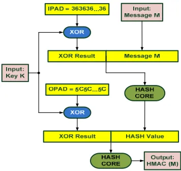
[image:6.612.217.395.190.358.2]The purpose of the HMAC is to authenticate the source of a message and its integrity [NIST:FIPS198 2002] by attaching a MAC to the message. MACs are generated employing two functionally distinct parameters, which are the message input, M, and the secret key, K, whereas the basic component of HMAC is the employed hash function. Specifically HMAC consists of hash and XOR functions. The algorithmic procedure of HMAC is illustrated in Figure 1 [RFC2104 1997].
Fig. 1. HMAC algorithmic procedure
A hash function breaks up a message into fixed-size blocks and performs an iterative processing over them. For instance, MD5, SHA-1, and SHA-256 hash functions operate on 512-bit blocks, whereas SHA-512 operates on 1024-bit blocks. The size of the output, HMAC (M), is the same as that of the underlying hash function (128, 160, 256, or 512 bits in the case of MD5, SHA-1, SHA-256, or SHA-512, respectively), although it can be truncated if it is desired.
The US National Institute of Standards and Technology (NIST) recommends the transition from MD-5 and SHA-1 to the approved SHA-2 family (SHA-224, SHA-256, SHA-384, and SHA-512) of hash functions. At the same time, NIST has also launched a competition for the new SHA-3 hash function standard. Nowadays, this competition is at the Round 3 phase, where the 5 candidates for this round have been chosen and the final winner is expected to be announced in 2012 [NIST-SHA3 2011]. This means that current and future implementations of HMAC utilizing SHA-256 hash function will be used at least until 2020. Hence, the development of high-throughput hardware implementations for SHA-256 hash function and the corresponding HMAC module is important for future applications.
4.2 SHA-256 Hash Function
of identical or slightly different operations called transformation rounds or
operations.
According to the employed hash function, the input message, M, of length l is preprocessed (padding). The purpose of padding is to ensure that the input message is a multiple of 512 or 1024 bits (depending on the algorithm). In case of SHA-256, the message is parsed into blocks of 512-bit and at the end of its last block the bit ‘1’ is appended followed by k zero bits, where k is the smallest, non-negative, solution to the equation l + 1 + k = 448mod512. Then a 64-bit block that is equal to l in binary representation is appended.
The padded data are processed and divided in Message Schedules, Wt, to be used in each transformation round t. Next, the transformation rounds are applied using the message schedules, Wt, the initial hash values, (0) (0)
0 7
(H −H ), and constants, Kt. In
case of SHA-256 64 32-bit Wt words are produced by the message scheduling
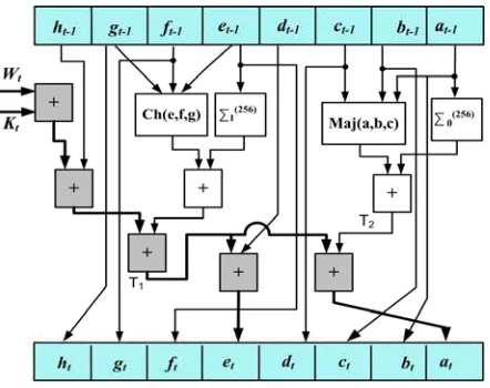
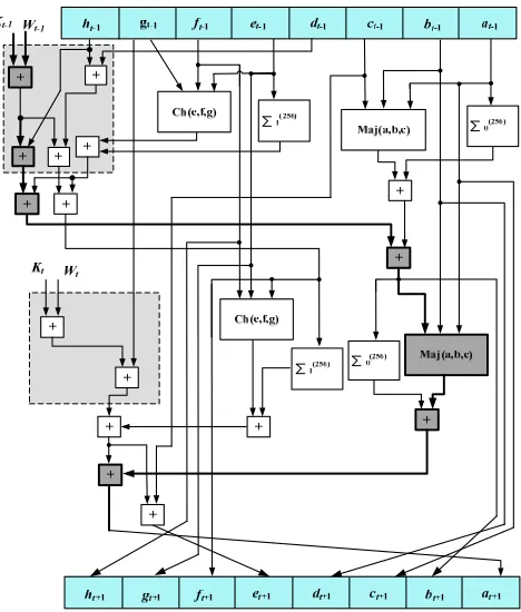
[image:7.612.198.419.275.450.2]procedure. The hash value is derived by applying 64 transformation rounds (operations). The block diagram of the transformation round is depicted in Figure 2.
Fig. 2. The SHA-256 transformation round
The (at-1 – ht-1) and (at – ht) boxes represent 32-bit words, whereas Wt and Kt are the message schedules and constants, respectively. It must be noticed that in the first iteration the initial hash values, (0) (0)
0 7
(H −H ), are used as (at-1 – ht-1). To produce the
output value, each transformation round includes modulo-32 additions and non-linear functions, which include simple logical functions. The incorporated functions in the transformation round are given in Eq. (1).
( , , ) (
) (
)
Ch x y z
= ∧ ⊕ ∧
x y
x z
( , , ) (
) (
) (
)
Maj x y z
= ∧ ⊕ ∧ ⊕ ∧
x y
x z
y z
256 2 13 22
0 ( )x =ROTR x( )⊕ROTR ( )x ⊕ROTR ( )x
∑
256 6 11 25
1 ( )x =ROTR x( )⊕ROTR ( )x ⊕ROTR ( )x
∑
(1)
The term ROTRm denotes ‘m’ times circular right rotation, whereas ∧ and
⊕
stand5. SHA-256 CORE – BASE ARCHITECTURE
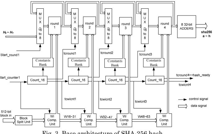
Concerning the hardware implementation of hash functions the widely used approach for high-throughput designs is the application of four pipeline stages [Michail et al, 2009]. This quadruples throughput by processing concurrently four different messages, whereas balances the introduced area penalty with the throughput improvement. The architecture of such design is depicted in Figure 3.
It consists of four pipeline stages called operational rounds (round 1, 2, 3, 4 in Figure 3), with a multiplexer in front of each one, while output registers are used at the end of each operational round. Each round corresponds to 16 transformation rounds (operations) of the algorithm, and thus an input message is processed 16 times in each pipeline stage resulting in 64 transformation rounds in total.
The 512-bit input blocks follow the padding formation implemented by a Padding Unit. This unit is implemented in software, since it reduces the complexity of the design without affecting its security level. Also, the constant values, Kt, which are known from the beginning of the transformation, are stored into registers (Constants Banks) and serve as inputs in each transformation round.
[image:8.612.142.485.346.562.2]The 16to8 multiplexers are used to input the previous round’s outputs (or the initial values for the first round) or to feed back current round’s outputs. In combination with the registers they form the 4-stage pipeline ensuring that four different 512-bit data blocks can be processed concurrently and a 256-bit message digest is produced every 16 cycles.
Fig. 3. Base architecture of SHA-256 hash
The production of the Wt values is performed by the Computation Unit blocks. Each Wi Computation Unit consists of: a) one 16xbit shift register, b) a 2to1 32-bit multiplexer, and c) a logic module that includes one 4-input adder (32-32-bit), four 32-bit XOR gates and 6 bit-level rotation blocks, properly arranged for the computation of a W value. This module computes one new W value per clock cycle, whereas its computation time consists of two addition stages, two XOR stages, and one 2to1 multiplexer stage, that is TWi_Comp_Unit= 2tXOR + 2tADD + tMUX, where tXOR, tADD, and tMUX are the delays of the 32-bit XOR, adder, and multiplexer, respectively.
-W31 values are computed (one per clock cycle) and stored into the unit’s shift register
through serial input. At the same time, in every clock cycle the appropriate Wi value is fed in the round. When the first round finalizes its computation the computed W16
-W31 values are transferred (through parallel load) to the shift register of the second Wi Computation Unit. There, the computation of the W32-W47 values starts
together with the second round’s computation. The same procedure takes place for the third and fourth Wi Computation Units, of the third and fourth round,
respectively.
The control unit is composed by four Count_16 Units, which control all
multiplexers. Each Count_16 component, also arranges the loading of the 16 Wi, in the next round’s shift registers. Their outputs are the counting values (010-1510)and
two control signals, tcwicnt_i and tcround_j, where i, j = 1, 2, 3, 4. The tcround_4 signal of the 4thCount_16 unit serves as handshake signal of the whole architecture
indicating the computation of the final hash value, whereas the tcround_j (j=1, 2, 3) signals are used as selectors in the 16to8 multiplexers. Each Count_16 unit is enabled only when there is a message that is being processed in the corresponding transformation round. This way power is saved when no message is supplied for process. When the process in each pipeline stage reaches the end, the Count_16
component arranges that the process will continue to the next pipeline stage. This is achieved by the control signal tcwicnt_i, which serves as enable signal for the
Count_16 unit and selector of the 2to1 multiplexor inside the Wi Computation unit
of the “i+1” pipeline stage. The enable signal of the first Count_16 unit and the select signal of the 2to1 multiplexor of the first Wi Computation Unit as well, are the core’s handshake signal Start_counter1. The signal Start_round1 is the selector of the first 16to8 multiplexer. They both indicate the beginning of the hashing process of a new inserted 512-bit input block.
Finally, at the end of the computation, the outputs from the fourth round are fed into 8 32-bit adders to be added with the initial values a – h and produce the final result. This addition consumes less than one clock cycle and does not increase the critical path.
The throughput of a hash function design is equal to:
cycles f bits Throughput
#
# ×
= (2)
The term #bits equals to the number of the bits processed by the hash function, the term #cycles corresponds to the required clock cycles to produce a hash value, and f indicates the operating frequency.
Exploring the architecture of Figure 3 and all its components that have been previously analyzed, it is derived that the critical path is located inside the transformation round (between the pipeline stages) and the multiplexer. Thus, to increase throughput, the effort should be focused on the optimization of the operational round.
The operational round of the base SHA-256 function’s architecture is illustrated in Figure 2. Taking into account that the non-linear functions given in Eq. (1) are simple logical operations, the delay of each of them is lower than the delay of the 32-bit adder. Therefore, the critical path of base architecture consists of the components which are marked darker in Figure 2. Specifically, it includes four adders for computing at or et and a multiplexer for selecting the appropriate values for feeding the operational round. Thus, the clock period, Tbase, of the base architecture equals to:
MUX ADD
base t t
6. DESIGN METHODOLOGY
A top-down design methodology for optimizing the throughput for several hash functions including the SHA-256 one has been proposed in [Michail et al, 2009]. Specifically, 5 optimization techniques have been proposed and applied leading to a SHA-256 design that achieves 3.3 Gbps throughput in Xilinx Virtex 2 FPGA technology. These techniques exploit specific properties of hash functions, such as the iterative nature of these algorithms, the use of limited logical and arithmetic operations, and certain spatial and temporal data dependencies.
The methodology that was introduced in [Michail et al, 2009] includes the following techniques. The first technique is the metric partial loop unrolling where the algorithm is unfolded allowing more operations to be performed in one clock cycle. The best number of operations to be unfolded has been determined by a separate analysis. The second technique is the spatial pcomputation and resources
re-ordering. At this step, units responsible for the calculation of intermediate values are
partitioned appropriately to disjoin in space several dependencies and enhance parallelism. The third technique is the data prefetching which pre-computes once-calculated values and feds them in the operational block. Then, at the fourth step
temporal pre-computation of dependant signals is performed. Finally, the fifth
technique is the input compression with Carry Save Adders (CSAs) units to further reduce the critical path.
However, due to their non-optimum exploitation in [Michail et al, 2009], the last two techniques failed to provide significant improvements compared to the other three ones. In this paper a modified and enhanced aspect of this methodology is presented leading to a more efficient way of applying the techniques related to the usage of CSAs and exploitation of temporal pre-computation. Also, the concept of recursive application of previously applied techniques (not introduced in [Michail et al. 2009]) is included to further improve the critical path and area. This modified methodology results to an optimized SHA-256 design with a reduced critical path compared to [Michail et al, 2009].
6.1 Improved Design Methodology for SHA-256 hash function
In this work two modifications concerning the optimization process of [Michail et al, 2009] are performed. It is proved that if the optimization process is applied recursively this leads to further improvements to the derived SHA-256 hash function design. Recursive optimization means that after the application of one technique all previously applied techniques are re-considered for application since in certain cases further improvements can be achieved.
The second modification is related to the order of applied techniques. It has been revealed that if the input compression with CSAs and temporal pre-computation techniques are reversed in their order of application, significant performance improvements can be achieved in conjunction with the recursive optimization.
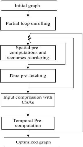
The introduced modified design methodology is illustrated in Figure 4, whereas in the following paragraphs the aforementioned modifications and their reasoning are discussed.
benefits. The recursive process should continue until no improvements are achieved (the graph does not further changes).
Fig. 4. Improved design methodology
The introduced concept of recursive optimization process designates that it is best to apply first those techniques that can benefit the proposed designs not only by their first application but by their reapplication during the recursive process as well. Generally, it is important to apply any technique more than once so as to exploit any opportunity for optimizing the performance of the design.
Due to its nature, the metric partial unrolling is excluded from the recursive process since it is dependent on the design constraints that are defined before the optimization process begins. Specifically, the unrolling value is determined by a separate analysis based on the area penalty that the designer is willing to pay to improve throughput, whereas the new resulting graph is considered as the feeding graph to the rest optimization process. If the area constraints change, a new analysis will be performed and a new graph will be produced. Hence, the metric partial
unrolling technique will be applied first and is excluded from the recursive process.
The spatial pre-computations with resources re-ordering is a changing-graph
technique that almost every time leads to significant performance improvements. This technique is quite flexible to be re-engineered and offers further optimizations after the application of the rest ones. Moreover, its drastic role in the whole optimization process through the great increase of degrees of freedom and great increase in performance indicates that this technique should be the second one. Also, as it is a changing-graph technique, it will be included in the recursive process.
outside the operational block. Hence, it was decided to be the third technique and, as it is a graph-changing technique, it is included in the recursive process.
Among the last two techniques, the input compression with CSAs is a
non-changing-graph technique as it merges two addition nodes to one with three inputs without moving the nodes or changing the data dependencies of the graph. On the other hand, the temporal pre-computation is a changing-graph technique as it moves graph nodes and changes the graph’s dependencies, as it will be illustrated in a following section. Therefore, based on the above reasoning the input compression with CSAs and temporal pre-computation should be the fourth and fifth techniques, respectively.
Changing the application order of the last two techniques is based on which of them allows the recursive process to “run” more times, so that these techniques are applied more than once. Specifically, if we choose to apply a non-changing graph technique (input compression with CSAs) last then the recursive process cannot take place after its application and the optimization stops at this point. On the other hand if a changing-graph technique (temporal pre-computation) is applied last then the recursive process takes place allowing all previously applied techniques to be
re-applied, leading to further improvements. Indicatively, if the temporal
pre-computation technique is applied last, after the input compression with CSAs, the
recursive process takes place and all the previously applied four techniques are re-applied. During this recursive process, the application of the input compression with CSAs can result in further improvements, since cases of adding three pending values may occur again.
7. PROPOSED SHA-256 DESIGN
In this section, based on the methodology of Section 6, the proposed SHA-256 design is presented in details. For each applied technique, including its recursive application, the produced design is presented and discussed. Also, the achieved operating frequency is given and compared with that of the base architecture.
7.1 Partial Loop Unrolling
Firstly, the algorithm is unfolded using the round un-roll technique. In that way, a number of replicas of operations (transformation rounds) are placed together producing a mega-operation block. Placing several operations together allows parallel calculation of independent values resulting in shorter computation times and higher throughput. However, this increases the total area of the design. The best ratio throughput/area for SHA-256 is achieved for two partially unrolled operations. This was determined by a comparative analysis on SHA-256 hash function, based on the derived throughput, the required area, and the calculated throughput/area ratio [Michail et al, 2009].
Partial loop unrolling of two operations means that two consecutive operations are merged resulting in a mega-operation block. This means that the values (at+1 – ht+1)
are computed based on the (at-1 – ht-1) values. This formulation is equivalently
Fig. 5. Two merged SHA-256 operational blocks
The critical path of the produced mega-operation block is now longer (6 additions and one non-linear function are needed to compute the at value). Namely, the new clock period, T1, is given by Eq. (4), where tnlf stands for the delay of the nonlinear function:
MUX nlf
ADD t t
t
T1 = 6 + + (4)
Compared to Eq. (3) the critical path increases by 2tADD + tnlf. However, the mega-operation block computes in one clock cycle (T1) the values that would be computed in
two cycles (2Tbase) if the architecture of Figure 2 was used. In addition, since the non-linear function is composed by simple operations, this means that 2tADD + tnlf < 4tADD thus, T1 < 2Tbase. Therefore, compared to the base architecture, the unrolled
implementation results at a reduction of the total execution cycles form 64 to 32 and hence it improves throughput according to Eq. (2).
7.2 Spatial Pre-Computation and Resources Re-Ordering
At this step, certain computational paths which are responsible for the calculation of intermediate values are partitioned appropriately to disjoin several dependencies and allow parallel execution. This is based on the fact that the output values ct+1, dt+1, gt+1, and ht+1 are derived directly from the input values at-1, bt-1, et-1, and ft-1, respectively, as shown in Figure 5. Thus, the critical path is determined by the output values at+1,
bt+1, et+1, and ht+1.
progress of calculation. These pcomputations can be mainly achieved by re-ordering the registers in space. Moving the pipeline stage to a proper intermediate point to store these intermediate calculated values, the critical path is reduced. However, apart from the pipeline registers, any other hardware resource can be moved in order to improve the critical path.
Combining the first two techniques, the operation block is divided into two stages, which are: a) the Pre-computation stage, which is responsible for the pre-computation of the values which are needed in the next mega-operation, and b) the Post-computation stage, which is responsible for the final Post-computations of each mega-operation, as shown in Figure 6.
The new critical path, whose components are marked darker in Figure 6, includes four additions, two non-linear functions (Maj and Ch), and one multiplexer. Thus, the new clock period, T2, equals to:
MUX nlf
ADD
t
t
t
T
2=
4
+
2
+
(5)Compared to the Tbase, the new clock period, T2, is slightly larger due to the two
non-linear functions but it performs in one cycle (T2) the computations of two
[image:14.612.183.436.341.590.2]operations. On the other hand, the base architecture consumes two clock cycles, (2Tbase) to perform the same computations. Thus, the throughput is improved by 80%-90%.
Fig. 6. Operational block after applying the first two techniques
As the initial graph is reorganized in two sub-graphs where the first sub-graph corresponds to the Post-computation stage followed by the Pre-computation stage (outputs’ feedback via the 16to8 Multipexers – Figure 3), it is clear that the spatial
pre-computation and resources re-ordering is a changing-graph technique. Therefore,
recursive optimization takes place according to the proposed design methodology. However, no extra benefits are achieved through re-application of spatial
7.3 System Level Data Pre-Fetching
The operational block of the SHA-256 function includes the use of constant values Kt and once-calculated values Wt. These values can be pre-computed, stored in registers and fed in the operational block when it is required. Thus, instead of calculating the Wt+Kt values inside the operation block, we can calculate the above sum for a number of Wtand Kt stored values enough time before they are really needed and provide the result directly to the hash core.
[image:15.612.186.431.241.454.2]Applying this technique to the operation block of Figure 6 does not result in critical path’s improvement, because the additions between the constant values are not located in the critical path. However, this technique enables the efficient application and/or re-application of the other techniques. The derived block after applying the first three techniques is shown in Figure 7.
Fig. 7. Operational block after applying data pre-fetching
7.4 Recursive Optimization
Based on the modified design methodology the previous applied techniques have to be re-applied. It was explained why metric partial unrolling can not be re-applied, so only the spatial pre-computations with resources re-ordering and the system level data
pre-fetching should be re-considered.
Investigating Figure 7, it is clear that moving the “Ch function” (circle 1, in Figure 7) from the Post-computation to the Pre-computation unit improves the critical path because the “Ch non-linear function” takes more time to be computed than the function Σ1(256). The “Ch function” can be computed in the Pre-computation unit, as
the necessary value p2 is now computed sooner due to the pre-fetching of values
Wt+1+Kt+1 and Wt+Kt to the operational block. The new position of the “Ch function” is
shown in Figure 8 (circle 3) resulting in a new intermediate value p6. The new critical
path, which is marked with darker blocks in Figure 8, consists of: four additions and three non-linear functions. Thus, the new clock period, T3, equals to:
3
4
A D D3
n lf M U XCompared to the T2, the new clock period, T3, is slightly larger due to the
[image:16.612.187.430.144.349.2]additional non-linear function. However, the re-ordering of the “Ch function” enables the efficient application of temporal pre-computation technique that will be applied later on and will significantly improve the critical path.
Fig. 8. Re-Application of Spatial Pre-Computation and Resources Re-Ordering
Since the graph’s dependencies have been changed as the “Ch function” has moved from the beginning to the end of the graph, the recursive process is re-applied once again. However, re-applying (2nd time) the spatial pcomputations with resources
re-ordering no further benefits are achieved and the graph does not change. Hereupon,
the re-application of system level data pre-fetching is performed leaving the graph unaltered yet again. Thus, the optimization continues with the application of the last two techniques.
7.5 Input Compression with CSAs
The next-applied technique is related to the exploitation of input compressing circuits which in case of SHA-256 hash function these are the CSAs. Due to the nature of SHA-256, CSAs can be used as adders which are the main components that contribute to the critical path. Indication for using this technique is the fact that there are some values pending to be added, until a similar process (addition) is ended [Kim et al. 1998].
Specifically, we try to trace cases where it is desired to add more than two pending values together and there is no full exploitation of the delay of the incorporated circuits. For example, adding three values requires the same time as for adding four values. So it is clear that in the case of adding three values there is no full exploitation of the delay of the two addition stages. The addition of the three values could be performed with a CSA resulting in a decreased delay (compared to the two addition stages) and also in an area reduction. In a CSA the delay for adding three values is reduced from two addition stages to one addition stage and the delay of a full adder cell (equal to three logic gates) [Kim et al. 1998].
The critical path of Figure 8 is located on the computation of the value p6.
However, at the beginning of this path while the addition between p6 and Σ1(256)(p2) is
being performed, the value p4 is pending until the previous addition finishes and thus
Figure 8 (circle 1). In that case, the CSA1 is used to add the three values (Figure 9). The same situation occurs for the computation of value at+1 as shown in Figure 8.
Thus, the two adders in circle 2 of Figure 8 are replaced by the CSA2 in Figure 9.
Fig. 9. Input Compression Exploiting CSAs
Furthermore, since the usage of CSA also results in saving area, cases of merging two adders in one CSA are further investigated. Two such cases are traced. Specifically, the addition of ht−1+dt−1+(Wt+1+Kt+1) in the Pre-computation unit
(circle 5 in Figure 8) is implemented by the CSA3 in Figure 9. Also, the addition of
∑
+
+ 256
1 2
5
6 p (p )
p (circle 4 in Figure 8) is realized by CSA4 (see Figure 9). It has to
be stressed that the employed CSA modules consist of a simplistic carry-save tree followed by a modulo-32 addition stage.
Putting together all optimizations described above, the modified operational block is shown in Figure 9. This block has a new critical path, which is the path for the computation of value p1 (darker blocks in Figure 9). The new critical path, T4, equals
to:
4
2
CSA ADD2
nlf MUXT
=
t
+
t
+
t
+
t
(7)where, tCSA, tADD, tnlf, and tMUX are the delays of the CSA, simple adder, non-linear functions, and multiplexer, respectively.
Since input compression with CSAs is a non-changing graph technique, the
recursive optimization does not take place and the optimization continues with the final technique.
7.6 Temporal Pre-Computation
Temporal pre-computation exploits, by register renaming, the existence of
[image:17.612.182.433.131.328.2]these pre-computations take place 4 or 5 clock cycles before (as discovered by observing the block of Figure 9).
To make the explanation of temporal pre-computation technique compact, let the notation Zt represent the conjunction of the 8 primary outputs of SHA-256 (at – ht) at the tth mega-operation. Then, the mega-operation t+1 is being calculated when the values Zt+1 are computed from the values of Zt-1, the values Wt, Wt+1 and the
corresponding Kt, Kt+1. Thus, Figure 9depicts the t+1th mega-operation.
Inspecting the Post computation unit of Figure 9, it can be seen that the current value of p2 derives directly the value of ft+1 at the next mega-operation. Also, the
value of ft+1 derives directly the value of ht+3 at the second following mega-operation.
Hence, the value of ht+3 is the same as the value of p2 was two mega-operations
earlier. Similar observations also hold for signals et-1 and dt+3. Thus, the following
equations are valid:
3 1 2 = ft+ =ht+
p (8)
3
1 +
+ = t
t g
e (9)
3 1 3
1+ p =bt+ =dt+
p (10)
Hence, in order to calculate the sub-sum Wt-1+Kt-1+ht-1, which is used to calculate
the value p3 (circles 2 and 7 in Figure 9), we calculate two mega-operations earlier the
sub-sum Wt-1+Kt-1+p2 (circle 4 in Figure 10) which is saved into the register H* at the
[image:18.612.189.428.413.613.2]next mega-operation, as shown in the Post-computation unit in Figure 10. In the Post-computation stage of the next operation this value is staying intact by just changing its name into H. Finally, in the Pre-computation stage of the second following operation (two clock cycles after the temporal pre-computation of the sum) it is consumed with no extra delay (adder in circle 3, Figure 10).
Fig. 10. Operational block after applying the temporal pre-computation technique
The same also holds for the calculation of values Wt-1 + Kt-1+ ht-1 + dt-1 and Wt + Kt
+ gt-1 (circle 4 and 3 respectively in Figure 9)which are saved in registers X* and P4*,
Regarding the critical path it remains unchanged. However, temporal
pre-computation achieves an area reduction by one CSA while the most important fact is
that it changes the operational graph. This allows the application of the recursive optimization that will further improve performance, as it will be shown in the next section.
7.7 Recursive Optimization
Since the previously applied technique of temporal pre-computation changes the operational graph, recursive optimization takes place according to proposed methodology to further improve performance. For this reason, all previously applied techniques are re-considered.
First the re-application of spatial pre-computation and resources re-ordering takes place (3rd re-application). The adder computing the value p3+p1 (in circle 1, Figure 10)
is re-ordered at the end of the Pre-computation unit so as to spatially pre-compute the value p3+p1. Moreover, spatial re-ordering of that part of the critical path, which
is responsible for adding p6 + p4 + Σ1(256)(p2) and the CSA which adds p6 + p5 + Σ1(256)(p2) (circles 5 and 6 in Figure 10, respectively) entirely to the Pre-computation
unit, is performed, thus improving the critical path as illustrated in Figure 11. Specifically, the CSA inside circle 6 bin Figure 10 is the CSA in circle 6 of Figure 11, whereas the CSA and function Σ1(256)(p2) (circle 5, Figure 10) are the CSA and
function Σ1(256)(p2) inside circle 5 of Figure 11, respectively. The re-ordering of the
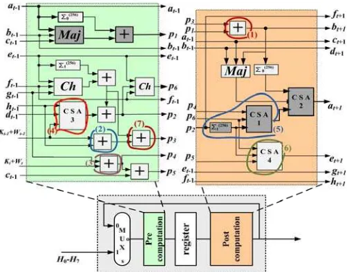
[image:19.612.190.423.387.600.2]resources of circle 5 of Figure 10 reduces the critical path by tCSA+tnlf . In addition, the moving of CSA4 and the resources of circle 1 of Figure 10 leads to balanced paths in the mega-operation block.
Fig. 11. Operational block after applying the spatial pcomputation/resources re-ordering (4th time) and data pre-fetching (2nd time) techniques
Since the graph has changed, by the spatial pcomputation and resources
re-ordering technique, the recursive optimization must be applied according to Figure 4.
application of the third technique related to system data pfetches (2nd re-application). However, the application of this technique left the graph unaltered without offering further benefit to the design.
Thereafter, we moved on to re-application of the input compression with
exploitation of CSAs technique. In this case, the adder in circle 1 of Figure 11 can be
merged with the one computing p1 resulting in the CSA1 of Figure 12. Furthermore,
the adder in circle 2 of Figure 11 can be combined with the one in circle 4 of Figure 11 forming the CSA3 in the Pre-computation unit of Figure 12. The adder in circle 2 of Figure 11 can also be combined with the one in circle 3 of Figure 11 forming the CSA2 in the Pre-computation unit of Figure 12.
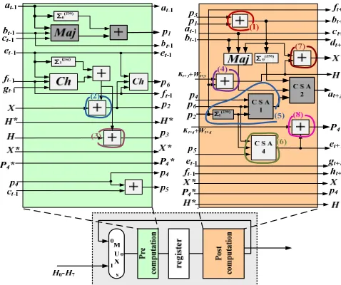
[image:20.612.181.433.266.503.2]Finally, the reapplication of temporal pre-computation technique takes place. However, the application of this technique left the graph unaltered. Consequently, at this point the optimization process ends and the final operational block of SHA-256 hash function is depicted in Figure 12.
Fig. 12. The final optimized block of SHA-256 hash function
7.8 Final Critical Path
Taking in consideration all changes that have been described it occurs that the critical path has changed and been reduced. New critical path is located in the computation of value p3 + p1 as highlighted with darker components in Figure 12.
Therefore, the final critical path of the design is given by the following equation:
5
2
CSA2
nlf MUXT
=
t
+
t
+
t
(11)The above critical path is reduced when compared to the one in [Michail et al. 2009]. Moreover the integration area penalty was kept low, exploiting the incorporation of more CSAs, resulted by the iterative nature of the improved methodology.
recursive optimization leads in the above performance improvement. In contrast, in [Michail et al. 2009] where the temporal pre-computation was applied before the
input compression with CSAs, the application of temporal pre-computation did not
offer any performance improvement, whereas recursive optimization was not applied. Thus, the proposed design outperforms the design of [Michail et al. 2009] in terms of throughput and throughput/area, as it will be shown in the experimental results.
7.9 Proposed Design Architecture of SHA-256 Hash function
In order to apply the optimization methodology, additional units are needed, the most important of which is the initialization unit. Specifically, to perform spatial and temporal pre-computation, certain values must be pre-computed and available before the hashing process begins. In particular for the first transformation round, apart from the 8 initial values that are given by the standard( 70)
0
1 H
H − , 6 more values
have to be computed before the beginning of its first iteration. These values arise taking in consideration the optimization techniques and the resulted transformation round in Figure 12. These values’ computation is described by the following equations:
X = ht-1+Kt+Wt+dt-1 (12)
H = ht-1+Kt+Wt (13)
P4 = Kt-1+Wt-1+gt-1 (14)
X* = bt-1+ft-1+Kt+2+Wt+2 (15)
H* = ft-1+Kt+2+Wt+2 (16)
P*4 = Kt+1+Wt+1+et-1 (17)
[image:21.612.231.382.506.649.2]The initialization unit, apart from computing the above values also feeds the first transformation round with the initial values. Its block diagram is illustrated in Figure 13. The above initialization takes place while the system is still receiving the message block (using its first already received part) and ends in less than one clock cycle (in time of 2 32-bit addition stages). Thus, it does not introduce any delay in the proposed SHA-256 hash core. Namely, no extra clock cycles are required and the critical path still resides inside the transformation round.
Fig. 13. SHA-256 Initialization Unit
The detailed architecture of the optimized SHA-256 function, including the
front of each round are employed so as to input the previous round’s outputs (or the initial values for the first round) or to feed back current round’s outputs. This way a message will be processed for 8 operations in one round and when this process ends in this round, the process will be continued in the next one.
The Block Split Unit is the same as in the base design architecture in Figure 3 whereas the four Wi Computation Units have been slightly modified so as to
process and produce 2 Wt in each clock cycle/mega-operation according to the new transformation round in Figure 12. (64 Wt in total for the full computation of the message digest). These Wt values are supplied in the “W + K” addition block of each round during the process of a message. The four added units, in shadowed blocks in the proposed architecture in Figure 14, compute the ‘Wt+Kt’ and ‘Wt+1+Kt+1’ values,
which are pre-fetched to the operational rounds. The necessary, Kt and Kt+1, constants
are stored in the Constants Banks, so as to be added to the appropriate Wtand Wt+1
respectively, coming from the corresponding Wi Computation Units or the Block
Split Unit. The values ‘Wt+Kt’ and ‘Wt+1+Kt+1’ are temporarily stored in two 32-bit
registers (REG).
Fig. 14. Final Architecture of the SHA-256 hash function
Due to the four-stage pipeline, four 512-bit data blocks can be processed at the same time. Each 512-bit input block is processed 8 times in each transformation round resulting in 32 transformations performed in total (in 32 clock cycles respectively). This also means that a 256-bit message digest can be produced every 8 clock cycles. For this reason, the control unit of the whole architecture is composed by four Count_8 Units counting up to 8. The rest functionality and I/O signals of these units are similar to the ones of Count_16 units, illustrated in Figure 3.
Finally, when the process of the fourth round ends, its outputs are fed into 8 32-bit adders, where their addition with the initial values ( 70)
0
1 H
H − takes place and the
8. INTRODUCED HMAC DESIGN ARCHITECTURE
HMAC utilizes two hash functions and its output is the same as that of the underlying hash function, (i.e. 256 bits concerning SHA-256). Two SHA-256 hash cores, as designed and presented in the previous section, are used for the proposed HMAC design architecture which is illustrated in Figure 15.
The HMAC architecture once powers up has to be initialized through activation of the input signal init. The initialization procedure corresponds to computing the hash values of two certain 512-bit blocks, which are the corresponding keys, and it is performed independently in the two SHA-256 cores at the same time. The 512-bit
Xorskey component contains simple XOR gates to compute the values “k0 xor ipad” and “k0 xor ipad”, which are needed in HMAC’s initialization. This initialization process is completed after 33 clock cycles.
When the above initialization finishes, the hash values from the outputs of the two SHA-256 cores are stored and then are used as the new initial values (H10−H70) by the two SHA-256 cores. Since these two values and the corresponding keys must be protected and treated as secret, they are stored in registers. This is the first time that a 512-bit message block may be supplied for process to the HMAC core and the
sendmes handshake signal is activated indicating that the system can accept a new
message so as to compute its HMAC value.
Fig. 15. Proposed HMAC-SHA-256 architecture
clock cycles have pass the processing on the first transformation round of the first SHA-256 hash core begins and the sendmes signal is activated again indicating that a new input message can be supplied to the HMAC design.
The message that entered in the first SHA-256 core is processed, and finally after 32 clock cycles its 256-bit hash value exits the first SHA-256 core. It is then stored in the intermediate register REG_b, along with padding bits and length information about the input message block in the second SHA-256 hashing core (message length is always the 256 bits that are produced from the first SHA-256 hashing core).
The 256-bit hash value beyond the register REG_b, also feeds the initialization unit of the second SHA-256 core. So in the clock cycle that is needed for formulating the 512-bit input message for the second SHA-256 core (from the 256-bit output hash value from the first SHA-256 core), also the initialization for processing this message at the second SHA-256 core has been performed (at corresponding unit of the second SHA-256). Moreover in the same clock cycle the necessary signals are generated so as to enable process at the second SHA-256 hashing core at the very next clock cycle.
Then the rest process for the HMAC value computation begins in the second SHA-256 hashing core which is also finalized after 32 clock cycles. Finally after 65 clock cycles in total (32 for each one of the two SHA-256 cores and one clock cycle for the intermediate REG_b padding-register), the final HMAC value is computed. One clock earlier the handshake signal Hmac_ready is activated so as to notify the host system that at the next clock cycle the HMAC value can be retrieved.
In the presented HMAC core, every 8 clock cycle a new message can be inserted for computation of its HMAC value. The utilized SHA-256 hashing cores incorporate four pipeline stages each. Thus, taking into consideration that the message receiving phase which lasts 8 or less clock cycles, it occurs that 9 different messages can be concurrently processed.
Fig. 16. HMAC Computation Flow
In normal operation, inputs ( 70) 0
1 H
H − are the hash values that were computed
Finally, the Control Unit produces the control signals used inside the HMAC core as well as the handshake signals (the functionality of which was described previously) which are used for communication and appropriate synchronization with the rest platform.
9. EXPERIMENTAL RESULTS AND COMPARISONS
The introduced architectures of the SHA-256 hash function and HMAC mechanism were captured in VHDL. Their correct functionality was verified through Post-Place and Route (Post-P&R) Simulation via the Model Technology’s ModelSim Simulator. A large set of test vectors, apart from the test example proposed by the standard, were used. Beyond that, downloading to actual FPGA boards was performed and the implementations’ correct functionality was verified via ChipScope. Many FPGA technologies were selected to implement the proposed designs such as FPGA families Virtex, Virtex II, Virtex II Pro, Virtex E, and Virtex 4. The above FPGA families were chosen for comparison reasons since a lot of SHA-256 designs have been synthesized on them and reported in the literature. Moreover, experimental results after place and route (P&R) were taken for FPGA families Virtex 5 and Virtex 6. The tool used for synthesis, mapping, and P&R the introduced designs to the targeted technologies was the XST synthesis tool of Xilinx ISE Design Suite.
It has to be mentioned that there is a limited amount of HMAC designs in FPGA published by academia or industry. This is due to the fact that the relevant research is focused on the optimization of the main module of the HMAC mechanism which is the utilized hash function. It is obvious from the HMAC architecture that the operating frequency and throughput of HMAC mechanism is determined by the SHA-256 hash function module. Hence, in order to make a fair comparison, we choose to provide separately detailed comparisons for the SHA-256 hash function, for which there exist many implementations proposed either by academia or industry. However, the implementation results of the proposed HMAC architecture are also provided.
In addition to frequency, throughput, and the occupied area, the fairer comparison and evaluation factor which is throughput/area ratio is also included. As different optimization techniques were applied on each design including the proposed one and these presented in the literature, it results in designs and implementations with different throughput and area values. Hence, to fairly evaluate the quality of each implementation, the throughput/area ratio is adopted in our study.
It must be stressed that in order to have a fair comparison, the architecture of
[Michail et al. 2009] was remapped using the Xilinx ISE Design Suite since a
different synthesis tool was employed in [Michail et al. 2009]. This proves that the achieved improvement is due to the modified optimization procedure that was proposed in this paper and the resulted optimized SHA-256 hash core and not due to the usage of more sophisticated and modern synthesis tools.
In Figures 17-21 the implementation results and comparisons between the proposed and existing SHA-256 hash designs are presented. Each figure includes a table where the area, frequency, and throughput values are provided and a chart where the corresponding throughput/area ratios are illustrated.
Concerning the throughput of the introduced architectures, two different values are provided, namely the value that is arisen after synthesis (post-synthesis) and that is derived after place and route (P&R). Also, as the area, frequency, and throughput strongly depend on the speed grade, we also provide the speed grade values that were used to implement the proposed architectures.
the throughput after synthesis equals to 3.8 Gbps and 2,943 slices were devoted for its implementation. Also, the throughput/area ratio equals to 1.02. Compared to the existing designs implemented on this technology, the proposed one outperforms them in terms of throughput (26% up to 4,780%) and throughput/area ratio (33.6% up to 3.229%).
Throughput (Mbps) References Freq.
(MHz)
Synthesis P&R Area (slices) [Dominikus 2002] 42.9 77 - 2008 [Ting et al. 2002] 88 87 - 1261 [Sklavos et al. 2005] 83 326 - 2120 [Chaves et al. 2006] 82 646 - 764 [Glabb et al. 2007] 77 308 - 1306 [Chaves et al. 2008] 82 646 - 764 [Rogawski 2009] - 856 - [Michail et al. 2009] 46.8 2995 - 3192
Proposed 58,7 3757 3667 2943
[image:26.612.132.485.146.262.2]Throughput/Area 0 0,2 0,4 0,6 0,8 1 1,2 1,4 [D om ini k us 2002 ] [T in g e t al. 2002] [Skl avos e t al . 2005 ] [C h av e s e t a l. 2 006] [G la b b et al . 20 07] [C h av e s e t a l. 2 008] [M ic h a il e t a l. 2 009] Pr opo se d Pr opo se d P& R
Fig. 17. SHA-256 – Xilinx Virtex family results
The proposed design was implemented in Virtex II FPGA family (Figure 18) with speed grade values 6 and 5. Compared to the competitive implementations, the proposed one (with speed grade equal to 6) outperforms them both in throughput (40.3% up to 8,373.9%) and throughput/area ratio (30.6% up to 2,046%). Also, compared to the design of CAST Inc, using the post place route values the throughput improves by 412%.
Throughput (Mbps) References Freq.
(MHz)
Synthesis P&R Area (slices)
[image:26.612.134.487.380.501.2][Chaves et al. 2006] 150 1184 797 [McEvoy et al. 2006] 133 1009 1373 [Chaves et al. 2008] 150 1184 797 [Zeghid et al. 2007] 81 1296 1938 [Zeghid et al. 2008] 56 896 1480 [Kim et al. 2009] 71.5 74,7 779 [Rogawski 2009] 1992
[CAST Inc.] 120 930 815
[Michail et al. 2009] 70.1 4485 2862 Proposed (-6) 98.9 6330 4768 3075 Proposed (-5) 85,9 5498 4132 3077
Throughput/Area 0 0,2 0,4 0,6 0,81 1,2 1,4 1,6 1,8 2 2,2 [C ha ve s et a l. [M cE voy et a l. [C ha ve s et a l. [Z eg h id et al. [Z eg h id et al. [K im et al . 200 9] [C A S T In c. ] [M ich ail et a l. P ropos ed (-6 ) P ropos ed (-5 ) P ropos ed P& R ( -6 ) P ropos ed P& R ( -5 )
Fig. 18. SHA-256 – Xilinx Virtex II family results
Throughput (Mbps) References Freq.
(MHz)
Synthesis P&R
Area (slices)
[Chaves et al. 2006] 174 1370 755 [Chaves et al. 2008] 174 1370 755
Proposed (-7) 118.1 7558 6375 3054
Throughput/Area 0 0,5 1 1,5 2 2,5 3 [C ha ve s
et al. 20
06]
[C
ha
ve
s
et al. 20
[image:27.612.129.486.82.192.2]08] Pr opos ed (-7 ) Pr opos ed P & R (-7 )
Fig. 19. SHA-256 – Xilinx Virtex II Pro family results
Throughput (Mbps) References Freq.
(MHz)
Synthesis P&R Area (slices) [Michail et al. 2005] 64.1 2052 2930 [Michail et al. 2009] 49.1 3142 3006
Proposed (-8) 66.8 4275 3968 3181
Proposed (-6) 52.5 3360 3187 3190
Throughput/Area 0 0,5 1 1,5 [M ich ail
et al. 2005
]
[M
ich
ail
et al. 2009
[image:27.612.130.487.245.340.2]] Pr op os ed (-8 ) Pr op os ed (-6 ) Pr op os ed P & R (-8 ) Pr op os ed P & R (-6 )
Fig. 20. SHA-256 – Xilinx Virtex E family results
Additionally, the proposed 256 architecture is compared to commercial SHA-256 implementations in Virtex 4 technology (Figure 21). In this case only the post place and route values (P&R) are used for comparisons.
References Freq. (MHz)
Throughput (Mbps)
[image:27.612.112.504.429.541.2]Area (slices)
[CAST Inc.] 144 1116 829
[HELION Tech.
Ltd] 162 1256 758
[SoftJin Electronic
Design] 139 1079 754
Proposed P&R 130,1 8326 3963
Throughput/Area 0 0,5 1 1,5 2 2,5 [C
AST Inc.]
[H E L IO N Tec h. L td] [S o ftJ in El ect roni c De s ig n ] Pr op osed P&R
Fig. 21. SHA-256 – Xilinx Virtex 4 family results
Again the proposed implementation outperforms the competitive ones both in throughput (562.9% up to 671.6%) and throughput/area ratio (70.2% up to 109.4%). Apart from the above reported results, the proposed SHA-256 design was also implemented in Xilinx Virtex 5 and Virtex 6 FPGAs. The implementation results (Post P&R) are presented in Table I.
Table I. Implementation Results of the proposed SHA-256 Hash Design in Xilinx Virtex 5 and Virtex 6
Virtex 5(-3) 169 10816 1885
Virtex 6(-3) 172 11008 1831
As it is shown in Table I, the achieved throughput after place and route in Virtex 6 technology exceeds 11 Gbps.
Furthermore, the introduced SHA-256 hash core was compared with a conventional 4-stage pipeline (see Figure 3) where no special optimization effort has been paid to optimize the operation block. This was done so as to exhibit the efficiency of the proposed design methods and produced SHA-256 core. The proposed SHA-256 operation block results in a 170% increase of throughput and 35% area increase. This area penalty is about 10% for the whole security scheme that we considered for the IPSec and which also includes AES encryption algorithm. This is based on the fact that an IPSec core includes the AES, hash function and the corresponding control logic. Based on previous AES implementations [Hodjat et al. 2004; Granado-Criado et al. 2010] it is derived that their area sizes are similar to that of the of the SHA-256 core. Thus, assuming a 10% area overhead for the control logic the area penalty is about 10% for the whole security scheme. Since recent implementations of AES have much higher throughput and operating frequencies, this means that the proposed implementation achieves a great increase of throughput for the whole security scheme with a minor area penalty.
[image:28.612.157.459.80.109.2]To the best of authors’ knowledge an HMAC implementation that incorporates the SHA-256 hash function unit does not exist in the literature. Thus, we provide in Table II the implementation results (Post P&R) of the proposed HMAC architecture without comparisons, in a wide variety of FPGAs and speed grades.
Table II. Implementation Results of the proposed HMAC Architecture
PLATFORM FREQ. (MHz) THROUGHPUT (Mbps) AREA (Slices)
Virtex 50.1 3,206 6,964
Virtex II (-5) 65 4,130 6,832
Virtex II (-6) 70.6 4,521 6,835
Virtex II RRO (-7) 96.3 6,163 6,789
Virtex E (-6) 49.5 3,168 6,874
Virtex E (-8) 60.2 3,852 6,883
Virtex 4(-12) 130.1 8,326 7,123
Virtex 5(-3) 163.8 10,483 4,219
Virtex 6(-3) 170.1 10,886 4,028
As it is shown in Table I, the achieved throughput after place and route in Virtex 6 technology is 10.8 Gbps.
10. CONCLUSIONS
A novel hardware design and implementation of SHA-256 hash function and of corresponding HMAC mechanism for use in high-throughput demanding applications like IPSec was presented. The proposed design presents significant improvement both in throughput and throughput/area cost factor and outperforms when compared to all previously proposed, either by academia or industry, designs and implementations. Certain modifications have been applied on the optimization design methodology that the authors had presented in [Michail et al. 2009]. The modified optimization procedure led to the optimized SHA-256 hash core.
[image:28.612.150.464.390.515.2]security scheme. Significant design effort was paid to keep area small as well. The experimental results showed that a negligible area penalty was introduced for achieving such a high throughput.
REFERENCES
CASTINC.SHA-256Core. Commercial IP Datasheet. http://www.cast-inc.com/cores
CERF VINT. 2010. Vint Cerf pushes for NZ IPv6 transition., ComputerWorld The voice of the ICT community, Portal. Press Room. http://computerworld.co.nz/news.nsf/news/vint-cerf-pushes-for-nz-ipv6-transition
CHAVES R., KUZMANOV G.K., SOUSA L. A. AND VASSILIADIS S. 2006. Improving SHA-2 Hardware Implementations. In Proceedings of Workshop on Cryptographic Hardware and Embedded Systems (CHES 2006). Yokohama, Japan. pp. 298-310
CHAVES R.,KUZMANOV G.,SOUSA L., AND VASSILIADIS S. 2008. Cost-efficient SHA hardware accelerators. IEEE Trans. Very Large Scale Integr. Syst. 16, 8 (Aug. 2008), 999-1008. DOI= http://dx.doi.org/10.1109/TVLSI.2008.2000450
DOBBERTIN H. 1996. The Status of MD5 After a Recent Attack. RSALabs’ CryptoBytes. Vol.2, No.2
DOMINIKUS S.2002. A Hardware Implementation of MD4-Family Hash Algorithms. In Proceedings of IEEE International Conference on Electronics Circuits and Systems (ICECS'02). Dubrovnik, Croatia. pp.1143-1146
DORASWAMY N. AND HARKINS D. 2003. IPSec – The New Security Standard for the Internet, Intranets and Virtual Private Networks. Second Edition. Prentice-Hall PTR Publications, New Jersey, USA.
FRIEDL S. 2003. An Illustrated Guide to IPSec. Online Document. http://www.unixwiz.net/techtips/iguide-ipsec.html
GLABB R.,IMBERTB L.,JULLIENA G.,TISSERANDB A. AND CHARVILLON N.V. 2007. Multi-mode operator for SHA-2 hash functions. J. Syst. Archit. 53, 2-3 (Feb. 2007), 127-138. DOI= http://dx.doi.org/10.1016/j.sysarc.2006.09.006
GRANADO-CRIADO J.M.,VEGA-RODRIGUEZ M.A.,SANCHEZ-PEREZ J.M. AND GOMEZ-PULIDO J.A.2010. A new methodology to implement the AES algorithm using partial and dynamic reconfiguration. Integration, The VLSI Journal. 43, 72-80
HELION TECHNOLOGY LTD . Data Security Products. Commercial IP Datasheet. http://www.heliontech.com/auth.htm
HODJAT A., VERBAUWHEDE I. 2004. A 21.54 Gbits/s Fully Pipelined AES Processor on FPGA. In Proceedings of the 12th Annual IEEE Symposium on Field-Programmable Custom Computing Machines (April 20 - 23, 2004). FCCM. IEEE Computer Society, Washington, DC, 308-309.
JOHNSTON D. AND WALKER J. 2004. Overview of IEEE802.16 Security. IEEE Security and Privacy.
KHAN,E.,EL-KHARASHI,M.W.,GEBALI,F., AND ABD-EL-BARR,M. 2005. A reconfigurable hardware unit for the HMAC algorithm. In Proceedings of ITI 3rd Int. Conf. on Information and Communication Technology. Cairo, Egypt. pp. 861–874
KIM M., KIM Y., RYOU J., AND JUN S. 2007. Efficient Implementation of the Keyed-Hash Message Authentication Code Based on SHA-1 Algorithm for Mob