©IJRASET: All Rights are Reserved
552
Experimental Study on Process Parameters of
Tungsten Inert Gas (TIG) Welded AL6063/SiCp
Metal Matrix Composites
Shaninder Kumar1, Rajesh Kumar2, Rakesh Kumar3
1, 2, 3
Department of Mechanical Engineering, Sant Longowal Institute of Engineering and Technology Longowal-148106, Sangrur (Punjab)
Abstract: In the era of 21st century, advanced materials viz. super alloys, ceramics, composite materials plays vital role in various fields such as automotive industry, aerospace engineering, electronic packaging etc. Aluminium Metal Matrix Composites (AMMCs) are becoming more popular as structural materials and joining them is therefore of paramount importance.
The advantage of Aluminium – Matrix composites over normal Aluminum alloys are that they have improved mechanical properties like high melting temperature, ultimate strength, electrical and thermal conductivities, friction coefficient, wear resistance and thermal expansion coefficient, which is attractive for structural applications but due to poor weldability applications of AMMCs are limited.
The objective of thesis is to deliver a MMC with a inexpensive and basic production route i.e. stir casting method and to seek for outcomes of effective welding of AL6063 / SiCp AMMCs by GTAW process for possible basic applications. Subsequently welding the sample are tested to check the micro-hardness, conducted Tensile and Impact Test to analyses the properties of welded AMMCs and optimize the outcomes with the help of Taguchi’s Techniques.
Welding current 135A,GFR 12 l/m and 1.5mm/sec of welding speed is obtained as optimal parametric setting for Tensile Strength and same combination of 135 A of welding current, 12 l/min of GFR and 1.5 mm/sec is obtained for Impact strength and Micro-Hardness as optimal parametric setting.
Keywords: AMMCs, TIG, Taguchi’s analysis.
I. COMPOSITES
A “composite” can define when two or more dissimilar materials are combined together at microscopic level to produce a greater and single material. The structural material in which one constituent is called the reinforcement and another is called the matrix and these are not soluble in each other, the reinforcing material may be in utilizing in the particulate form, flakes or elongated flaks and the material of matrix are present in continuous. Aluminum based metal matrix composites (MMCs) reinforced with ceramic particles such as (Graphite, SiCp etc.) are mixed at a microscopic level and having better properties than individual constituent.
A. Aluminium Matrix Composites (Amcs)
AMC’s are MMC where metal is of Aluminium. AMC’s are comprise of two constituents in which one is matrix part ie. Aluminium and other is reinforcement which could be in the form of continuous/discontinuous fibre, whisker or particulates and which is commonly ceramics such as AL2O3, SiC etc. AMC’s allude to the class of light weight and high performance, Aluminium as focus material system. These materials are high requesting for various applications like aeronautical, marine etc. due to their high strength to weight ratio.
B. Processing of Composites
There are various processes for processing of aluminium matrix composites such as investment casting, pressure casting, high pressure inflation casting, infiltrations casting, hot-die mould casting, solid state casting, Liquid State Processes as stir casting etc. In the present study, AMC is processed with stir casting.
The Stir casting technique involves incorporation of reinforcement material into liquid metal melt during vortex phase created by
©IJRASET: All Rights are Reserved
553
a DC motor. In this process, the reinforcement material mixed into liquid matrix material by mechanical mixing. It is stirring in the furnace is important element of the stir casting process.A major problem associated with the stir casting process is that, the separation of reinforcing particles which is caused due to settling of the reinforcement particles during the melting and casting processes. The final distribution of the particles in the solid depends on material properties and process parameters such as rate of solidification, relative density, strength of mixing, and wetting condition of the particles with the melt.
The positioning of the particles in the liquid matrix based on the geometry of the mechanical stirrer, mixing parameters, arrangement of the mechanical stirrer in the dissolve, liquefying temperature, and the attributes of the particles included.
C. Tig Welding
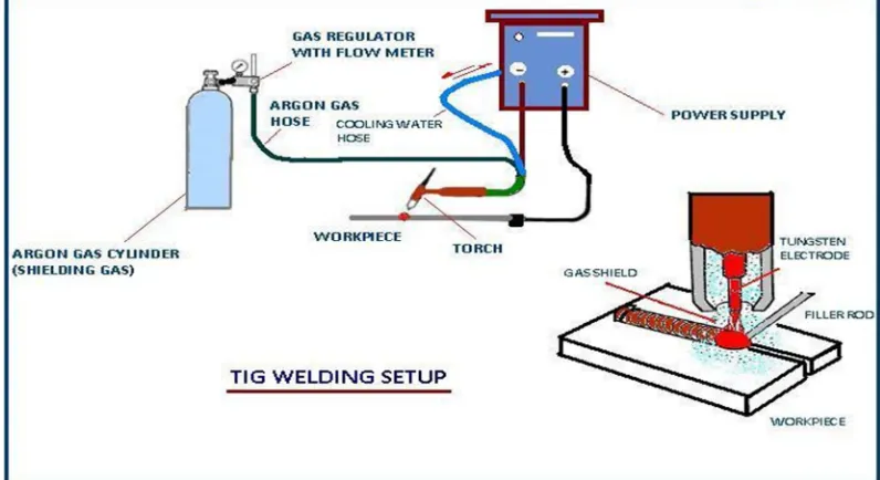
[image:2.612.105.503.302.519.2]The Gas tungsten arc welding (GTAW) process usages the heat of an arc between a non-consumable tungsten electrode and the base metal. The arc creates intense heat around 6100 ˚C, which melts the surface of base metal to form molten pool. Filler metal isn't included when thickness is 1 mm or less, edge joints and flange joints are welded. This is known as autogenous welding. For thicker materials an outwardly fed or cold filler rod is generally used. The filler metal isn' transferred across the arc but dissolved by it. The arc is protected from the atmosphere by the inert shielding gas, which flows from the nozzle of torch. The shielding gas replaces the air, so that the oxygen and the nitrogen of the air don't interact with the molten metal or the hot tungsten electrode. As the molten metal cools, coalescence occurs and the parts are joined. There is little or no spatter and little or no spatter and little or no smoke.
Figure 1: TIG welding setup
D. Polarite
There are three different polarities used in TIG welding which applicable.
1) Direct-Current Electrode Negative (DCEN): DCEN as straight polarity is general used in TIG welding process. In this polarity the tungsten electrode is connected to the negative terminal due to which it will only receive 30% of the GTAW energy.
2) Direct-Current Electrode Positive (DCEP): CDCEP as reverse polarity is another type of polarity used in TIG welding. The electrode is connected to the positive terminal of the power source.
E. Taguchi Orthogonal Array
©IJRASET: All Rights are Reserved
554
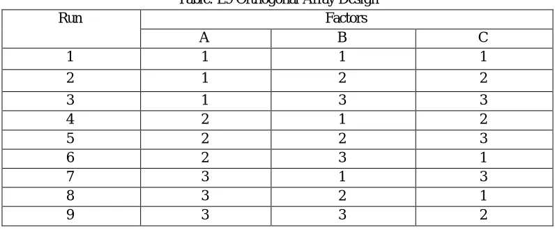
1) Factors: The number of columns in an array represents the maximum number of variables that can be handled by this array. A, [image:3.612.107.505.120.285.2]B, C indicates Welding current (A), Shielding Gas Flow Rate (l/min), Welding speed (mm/sec) as shown in Table.
Table: L9 Orthogonal Array Design
Run Factors
A B C
1 1 1 1
2 1 2 2
3 1 3 3
4 2 1 2
5 2 2 3
6 2 3 1
7 3 1 3
8 3 2 1
9 3 3 2
F. Experimenation
The objective of the experimentation is to optimization of GTAW process parameter during welding of AL6063/18%SiCp MMC. An L9orthogonal array was employed to examine the effect of Welding Speed, Current and Shielding gas flow rate.
Work material
1) Aluminium alloy 6063: AA6063 is a medium strength alloy commonly referred to as an architectural alloy. It is normally used in intricate extrusions. It has a good surface finish; high corrosion resistance is suited to welding and can be easily anodized.
Table-2: Composition of AL 6063
Element Al Mn Zn Si Mg Fe Percentage (%) 98.72 0.021 0.013 0.370 0.542 0.200
G. Processing Steps For Stir Casting
To make the AA 6063/ SiCp MMCs as work sample, the reinforcement is mixed in aluminium metal matrix by liquid state process i.e. stir casting of MMCs
1) The matrix material (A6063) is charged in graphite crucible and first heated above its liquidus temperature 750°C.
2) After it is cooled down to a temperature between the liquids (635°C) and solids (477°C) points.
3) The reinforcement particles (SiCp) are preheated to 900°C for 50 minutes before adding, after that added in to matrix material at semi solid state and mixed with help of stainless stirrer.
4) The slurry is again heated to liquid state and mixed thoroughly
5) A stainless-steel stirrer is lowered into the molten metal slowly up to 2/3 of the height of the molten metal from the bottom of the crucible.
6) The preheated SiC particles are added into the molten metal at a constant rate.
7) Simultaneously, 1 % of magnesium is added into the molten melt to improve the wettability between the SiC particles and alloy melt.
8) The mixture is poured into the mould and allowed to solidify. The prepared casting is taken out of the mould after 30 minutes.
©IJRASET: All Rights are Reserved
555
Figure 5: Molten Metal Poured into MouldH. Milling Operation
Now, these casted composite plates are surface finished to get desired dimension by using milling machine and after the casting process.
1) Joint Design And Edge Preparation: Two plates of 65 mm length, 50 mm width and 5 mm thickness has joined by TIG welding and single V grove joint. .
[image:4.612.116.490.288.429.2]2) TIG Welding Of Work Specimens: In the present study GTAW of SiCp reinforced AMC plates by using AC polarity. Since AC polarity is having cleaning properties so it has given good weld on the work specimen as shown in fig. Filler used or welding in Aluminium ER 5356 alloys as discussed above. Welded work specimens are shown in fig 6 .
Figure 6: Welding of Plates Figure 7: Welded Plate
I. Design Of Experiments (DOE)
The basic parameters selected for the current experimental study are welding current (A), shielding gas flow rate (l/min), welding speed (WS) with total of 9 numbers of experiment. The welding parameters and their level are given in Table.
Table 3: Experimental parameters and their levels S.No. Process
Parameter
Symbol Unit Level 1 2 3 1 Welding current I A 125 130 135
2 GFR GFR l/min 12 14 16
3 Welding speed WS mm/sec 1.50 2.00 2.50
Table 4: L9 Orthogonal Array
Run Welding Current (A)
GFR (l/min)
[image:4.612.64.534.491.733.2]©IJRASET: All Rights are Reserved
556
J. Response Parameters (Outcomes)These are performance measures or the outcomes which considered in the TIG welded joint of AA6063/18% SiCp AMMC are:
1) Tensile test
2) Impact strength (Charpy test)
3) Micro-hardness (VHN)
K. Tensile Testing
After the test perform to measure the final gauge length and compute elongation. The length has been estimated according to the gauge marking and mechanical properties.
Figure 8: Before test specimen Figure 9: After test specimen
L. Impact Testing
[image:5.612.146.471.379.545.2]The Impact properties of materials depend mainly on the toughness of the material. Toughness is the resistance of metal to fracture after plastic deformation has begun and finished by the impact of the pendulum which strikes the test piece as it swings through its path. Impact testing is done at metallurgy Lab in Mechanical Department, SLIET Longowal as shown fig 10.
Figure 10: Impact Testing Machine at Metallurgy Lab, SLIET Longowa
[image:5.612.141.470.575.713.2]©IJRASET: All Rights are Reserved
557
II. RESULT AND DISCUSSION
[image:6.612.40.577.128.280.2]The results obtained after doing casting and testing of AMMCs (AA 6063/18 % SiCp), work specimens, is listed in table impact strength, tensile strength and micro-hardness.
Table-5: Experimental Calculations
Run No. Welding Current (A) GFR (l/min) Welding Speed (mm/sec) Impact Strength (Joule) Micro Hardness (VH) UTS (MPa)
S/N ratio for Tensile test
S/N ratio for Impact Strength
S/N ratio for Micro hardness 1 125 12 1.50 6 76.44 55.12 34.82 15.56 37.66 2 125 14 2.00 5 70.32 35.15 30.91 13.97 36.94 3 125 16 2.50 4 66.43 34.28 30.70 12.04 36.44 4 130 12 2.00 9 77.12 58.38 35.32 19.08 37.74 5 130 14 2.50 7 67.11 31.28 29.90 16.90 36.53 6 130 16 1.50 9 78.47 54.23 34.68 19.08 37.89 7 135 12 2.50 10 74.22 58.21 35.30 20.00 37.41 8 135 14 1.50 12 84.22 52.24 34.36 21.58 38.50 9 135 16 2.00 11 82.18 70.20 36.92 20.82 38.29
A. Analysis Of Micro-Hardness
Table-6: Analysis of Variance for S/N for Micro Hardness
Source DF Sum of Square
Mean Square
F-Value P-Value
Welding Current (AZ 2 129.330 64.665 34.02 0.029 GFR (l/min) 2 7.506 3.753 1.97 0.336 Welding Speed (mm/sec) 2 172.486 86.243 45.37 0.022
Error 2 3.802 1.901
Total 8 313.124
Since the P-value in the Table is below than 0.05, there is a significant relationship between the variables at the 95.0% confidence level. The dependable variable Micro- hardness (VH) and there is dependable variables namely welding current (A), GFR (I/min) and welding speed (mm/sec) are get the significance of tests and then prepare the model.
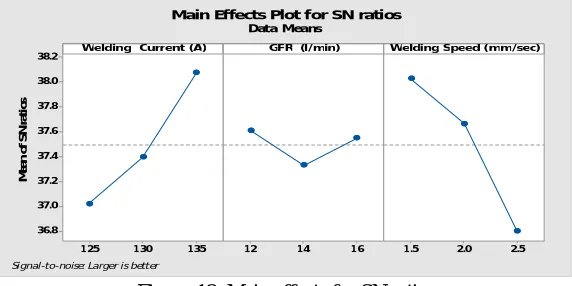
B. Main Effects Plot for S/N ratios for micro Hardness
The main effect plots for S/N ratios are shown in Figure. This plot shows the variation of micro-hardness (VHN) with change in three parameters; welding current (A), GFR (l/min) and welding speed (Ws). In the graph, the x-axis describes the value of each
[image:6.612.163.449.545.688.2]process parameters, y-axis the respective performance measure value (Micro-hardness). Horizontal line describes the mean value of the response or micro-hardness. The main effects graphs are drawn to get the optimal design to get the required optimum Micro-hardness. Main effects plots for Micro-hardness here are plotted between.
Figure-13: Main effects for SN ratios
Fig Main Effects Plot for S/N ratios for micro hardness Based on above analysis, it is observed that the optimal combination to get the higher value of Micro hardness according to optimal settings A3B1C1.
1 35 1 30 1 25 38.2 38.0 37.8 37.6 37.4 37.2 37.0 36.8 1 6 1 4
1 2 1 .5 2.0 2.5
Welding Current (A)
M e an o f S N r a ti o s
GFR (l/min) Welding Speed (mm/sec)
Main Effects Plot for SN ratios
Data Means
©IJRASET: All Rights are Reserved
558
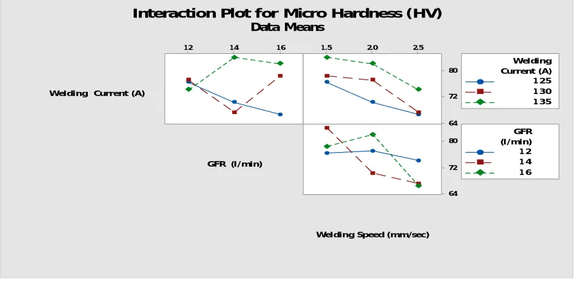
C. Interaction Plot for Micro HardnessFigure shows the interaction plot for micro hardness. In this plot there is interaction in some cases. Interaction is mainly in cases related to Shielding Gas Flow Rate. If the lines are parallel that means there is no interaction. Shapes of the lines would be more versatile if the strong interaction will be there. In the present study, interaction in between welding current and welding speed is studied, since lines are nearly parallel, which shows there is no interaction.
Figure-14: Interaction Plot for Micro Hardness
D. Analysis Of Tensile Strength
Table 7: Analysis of variance for S/N for Tensile Strength
Source DF Sum of Squares Mean Square F-Value P-Value
Welding Current (A) 2 541.39 270.70 21.63 0.044
GFR (l/min) 2 509.49 254.75 20.35 0.047
Welding Speed (mm/sec)
2 336.86 168.43 13.46 0.069
Error 2 25.03 12.52
Total 8 1412.78
[image:7.612.78.539.554.718.2]E. Main effects plot for S/N Ratios for Tensile Strength
Figure-15: Main effects plot for S/N ratios for Tensile strength
1 6 1 4
1 2 1 .5 2.0 2.5
80 72 64 80 72 64
Welding Current (A)
GFR (l/min)
Welding Speed (mm/sec)
1 25 1 30 1 35 Current (A) Welding 1 2 1 4 1 6 (l/min) GFR Interaction Plot for Micro Hardness (HV)
Data Means 1 35 1 30 1 25 36 35 34 33 32 1 6 1 4
1 2 1 .5 2.0 2.5
Welding Current (A)
M e a n o f S N r a ti o s
GFR (l/min) Welding Speed (mm/sec)
Main Effects Plot for SN ratios Data Means
©IJRASET: All Rights are Reserved
559
The main effect plots for S/N ratios are shown in Figure. These show the variation of tensile strength (MPa) with the three parameters i.e. welding current (A), GFR (l/min) and welding speed (mm/sec) separately. In the graph, the x-axis describes the value of each process parameters, y-axis the respective performance measure value (tensile strength). Horizontal line describes the mean value of the response or micro-hardness. The main effects graphs are drawn to get the optimal design to get the required optimum tensile strength. [image:8.612.95.517.171.359.2]F. Interaction Plot for Tensile strength
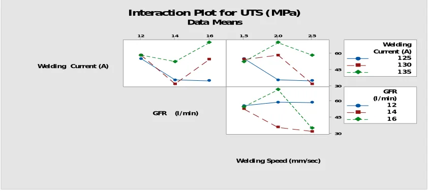
Figure-16: Interaction Plot for Tensile Strength
Figure shows the interaction plot for Tensile Strength (MPa). In this plot there is interaction in some cases. Interaction is mainly in cases related to welding speed. If the lines are parallel that means there is no interaction. Shapes of the lines would be more versatile if the strong interaction will be there. In the present study, interaction in between welding current and welding speed is studied, since lines are nearly parallel, which shows there is no interaction.
Table 8: Validation of Results
Performance response Predicted S/N ratios Optimal Parametric Settings After Confirmation tests
Impact strength 22.4154 A3B1C1 22.9753
Micro strength 38.7138 A3B1C1 37.4352
Tensile strength 37.9814 A3B1C1 37.1367
III. CONCLUSION
A. AL 6063 / 18% SiCp when joined by TIG process using ER 5356 filler rod shows good weldability and very good joint strength as the fracture has taken place from the base metal nearer to the HAZ.
B. Response table for S/N ratio for impact strength revealed that welding current makes highest contribution in impact strength and is the most significant factor.
C. Optimum parametric settings for higher impact strength is A3 (welding current 135A), B1 (GFR 12 l/min), C1 (1.5 mm/sec welding speed).
D. Optimum parametric settings for higher micro-hardness is A3 (welding current 135A), B1 (GFR 12 l/min), C1 (1.5 mm/sec welding speed).
E. Optimum parametric settings for higher tensile strength is A3 (welding current 135A), B1 (GFR 12 l/min), C1 (1.5 mm/sec welding speed).
F. As per Taguchi’ experimental, welding parameters for best quality weld are Welding current: 135 A, GFR: 12 l/min and Welding speed: 1.5 mm/sec
1 6 1 4
1 2 1 .5 2.0 2.5
60
45
30
60
45
30
Welding Current (A)
GFR (l/min)
Weldi ng Speed (mm/sec)
1 25 1 30 1 35 Current (A) Welding
1 2 1 4 1 6 (l /min) GFR
©IJRASET: All Rights are Reserved
560
REFERENCES
[1] Kaw, A. K. (2006). Mechanics of composite Material. London: Taylor& Francis Group, LLC. [2] Lubin. (1982). Hand book of composites. New York: Van Nostarnd.
[3] Mark, H. F. (1985). Encyclopedia of Polymer Science Engineering. New York: John Willy and Sons. [4] Chawla, K.K. (2006) Composite Materials: Science and Engineering, Springer New York, London.
[5] P. Srikanth, Ch. P Kumar. (2013). Electrical Discharge Machining Characteristics of Aluminium Metal Matrix Composites - A Review.,International journal of science and reserach.pp 1385-1394.
[6] J. Hashim, L. L. (1999). Metal matrix composites: production by the stir casting method. Elsevier Journal of Materials Processing Technology,pp 1-7. [7] Lai, K. T. (1999).In situ processing of Al–TiB2 composite by the stir-casting technique. Journal of Materials Processing Technology, 513-519.
[8] Lee, C. J. (2006). Processing of advanced Al/SiC particulate Metal Matrix Composites under intensive shearing – a novel Rheo process. Scripta Materials, 1415-1420.
[9] Lavernia, T. S. (1991). Processing techniques for particulate-reinforced metal aluminium matrix composites. Journal of Materials Science, 5965–5978. [10] https://en.wikipedia.org/wiki/Gas_tungsten_arc_welding.
[11] Carry B. Howard , Modern Welding Technology, Fifth Edition, page no-72. [12] https://en.wikipedia.org/wiki/Gas_tungsten_arc_welding/asp.
[13] Sindo Kou, 2. (2002). Welding Metallurgy 2nd Edition. John Wiley & Sons
[14] Ahmed Khalid Hussain, A. L. (2010). Influence of Welding Speed on Tensile Strength of Welded Joint in TIG Welding Process. International Journal of Applied Engineering Research, Dindigul , 518-525.