Copyright © 2012 IJECCE, All right reserved
An FPGA Based Multiple Output Ultrasonic Generator
with Two Step Iterative Resonance Detection
Ulvi Guvenc, Ali Tangel, Mehmet Yakut
1
Abstract — This paper presents design and prototype implementation of an FPGA-Based multiple output and multi-functional generator for ultrasonic cleaning machines. The complete generator design has two operating modes named as manual and automatic. The digital part of the complete design including frequency and PWM-controlled pulse generator and display driver unit to monitor power levels of four independent ultrasonic cleaning tanks has been implemented on a single FPGA core. As a result, four independent and fully-parallel cleaning process control have been achieved by way of the proposed modular design architecture. The main scientific contribution of this paper is to advertise a novel resonance frequency detection algorithm called as ―two-step iterative resonance frequency detection‖. As a result, capturing the resonance frequency for automatic operation mode becomes fast and precise. The paper also adresses the advantages of the FPGA based solution when compared to the traditional microcontroller-based counterparts. The new modular design also reduces the design complexity and provides flexibility to designer in case of different applications. The manual operating mode of cleaning system’s digital implementation consumes 65% of logic capacity while the automatic operating mode’s consumes 98% on a single Altera Cyclone-II FPGA having 5K of logic elements (LE).
Keywords — Ultrasonic cleaning, PWM generator, FPGAs, Embedded Design, Industrial Electronics.
I.
I
NTRODUCTIONThe term ultrasound is defined as mechanical oscillations whose frequencies are beyond the range of human hearing [1]. Cleaning with ultrasonic is based on using the high frequency sound waves to form millions of bubbles inside a liquid to cause explosion by vacuum energy named as cavitation, on surface of the objects placed inside a cleaning tank [2]. The cleaning technology is under development because of changing regulations and increasing ecological concerns. For instance, cleanliness has become important issue especially in electronic industry [3]. Ultrasonic cleaning systems are generally used to clean jewellery, watches, dental and medical instruments, lenses, and electronic parts of industrial equipments [1], [3]. Ultrasonic cleaning method has better cleaning effect when compared to traditional chemical based cleaning and physical methods [4].
Frequency, power and degassing time controls of cleaning process keep importance in designing ultrasonic cleaning systems [2]. So far, microcontroller based generator implementations have been preferred by designers. Different approaches about Pulse Width Modulation (PWM) generators based on microcontroller and Field Programmable gate Array (FPGA) can be reached in the literature [2], [4], [5], [6], [7], [8]. However,
few of them can directly be related to ultrasonic cleaning such as [2], [4], [5]. A microcontroller based solution for ultrasonic cleaning systems has also been introduced by the authors of this paper previously in [5]. But, it has been realized that microcontroller based approaches can’t be sufficient when multi-functional implementations are requested by customers. In addition, an FPGA based solution developed by authors presents two important advantages which cannot be accomplished by traditional microcontroller based solutions [2]. One of them is to reduce the step size for frequency adjustment as low as 5Hz for 48 KHz ultrasonic transducers to be able to catch the resonance frequency more precisely. The second one is to achieve independent and fully parallel multiple cleaning process control [2].
The contribution of this paper is to handle the drawbacks realized in earlier works about microcontroller and FPGA based ultrasonic cleaning systems existing in the literature [2], [5]. This study consists of a unique multiple-output frequency and PWM controlled ultrasonic generator digital implementation in a structural fashion using Very High Speed Integrated Circuits Hardware Description Language (VHDL). Although this structural design has some new functions, logic capacity utilization has remained almost the same as that of the earlier FPGA based work, [2]. In addition, it offers two different runtime operating modes of operation named as manual operating mode and automatic operating mode by updating its VHDL code only. That means more flexible hardware design on a single FPGA core. Moreover, a novel two-step iterative resonance frequency detection algorithm is also proposed to avoid undesirable effects arising from unstable cleaning tank loadings and some other physical factors during ultrasonic cleaning process.
The rest of the paper is organized as follows. Design architecture of the complete generator system is given in Section II. Section III explains the manual and automatic operating modes of the system. The related algorithms of the software are explained in Section IV. Finally, concluding remarks and discussions are given in Section V.
II.
D
ESIGNA
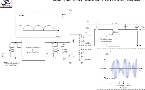
RCHITECTUREBlock diagram of the complete system is shown in Fig. 1. The electronic hardware of the complete ultrasonic cleaning system consists of five different sections as follows:
Copyright © 2012 IJECCE, All right reserved these digital hardware functions are designed as modular
VHDL component blocks and embedded on a single EP2C5T144C8 Altera Cyclone-II FPGA device. Realization of all these control processes only on a single FPGA core is a new approach in ultrasonic cleaning machine designs, and can be considered as one of the contributions of this paper.
Fig.1. Block diagram of the complete cleaning system 2) Signal conditioning/isolation unit includes a special optocouplor circuitry which is responsible for providing isolation between FPGA based digital control panel and ultrasonic power units. It converts the digital PWM signals obtained from FPGA core to a specific voltage range to be able to safely drive the power MOSFETS located in the DC-AC converter part of the ultrasonic power unit as shown in Fig. 2.
3) Mixed-Signal feedback unit is responsible for recovering the runtime resonance frequency of the cleaning system. Runtime frequency of the cleaning
system may change during the cleaning process due to unstable tank loadings. These shifting effects make the usage of a feedback unit necessary during the cleaning process. It is important to note that earlier works of the authors didn’t have any feedback unit implemented by using FPGA hardware. However, in an earlier study of the authors, it has already been advertised for 28 KHz ultrasonic cleaning system using a microcontroller. This paper, however, advertises an FPGA based new advanced frequency recovering technique, which can be considered as the main contribution of this study.
4) Transducer assemblies of the cleaning tanks are the very last stage of the complete cleaning system. Each transducer assembly has multiple ultrasonic transducers connected in parallel, and having the same natural resonance frequency of 48 KHz.
5) Ultrasonic power unit is used to generate amplitude-modulated sinusoidal signal to be applied to the ultrasonic transducer assemblies located under the cleaning tanks. A 48KHz, 1000Vpp modulated- sinusoidal signal is obtained from DC full-wave rectification of 220V main voltage. The conceptual circuit of the ultrasonic power unit is shown in Fig. 2.
Copyright © 2012 IJECCE, All right reserved
Fig.2. Conceptual circuit representation of the ultrasonic power unit
III.
M
ANUAL ANDA
UTOMATICO
PERATINGM
ODESThe developed generator system includes two different operating modes named as manual operating mode and automatic operating mode. Differences between manual and automatic operation modes are based on the style of determining the runtime resonance frequency of the complete cleaning system. In other words, manual recovering of runtime resonance frequency is named as the manual operating mode.
The hardware structure of manual operating mode is shown in Fig. 3. It consists of three separate circuits which are called and numbered as PWM generator module(1), monitoring module(2) and debouncing module(3). These circuits are designed in a manner of component style in VHDL code to be implemented on a single FPGA core. As can be seen in Fig. 3, the mentioned modules above are used multiple times in the complete system. The functions of these modules can be explained as follows:
1) PWM generator module is basically responsible for generating PWM signal pairs and providing power and frequency controls. This module is used four times to drive relevant ultrasonic power unit of cleaning tanks. Clock, reset, frequency up/down, power up/down are defined as inputs and PWM signal pairs, display data outputs are defined as output ports of the top level design. Local oscillator of the FPGA core is used to obtain the necessary clock signal when generating PWM signals through a clock divider VHDL code.
2) The monitoring module is used for monitoring the runtime power levels defined by PWM generator modules of the related cleaning tank. The operation of this module is based on time division multiplexing manner to authorize
four different seven segment displays sequentially. This method had to be chosen due to limited numbers of port pins available on the FPGA development board used. Therefore, a common data path is assigned to seven segment displays on the control panel.
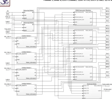
3) A debouncing prevention module usage is necessary because of push-buttons that are used for manual runtime power and frequency controls during the cleaning process. The structure of the other operation mode so called the automatic operating mode is shown in Fig. 4. In this mode, the runtime resonance frequency capturing is done automatically. Automatic operating mode has an additional module called as feedback module when compared to the manual operating mode, and provides us runtime resonance frequency capturing of the cleaning system by using its own analog/digital converter hardware assigned one for each cleaning tank assembly. Each analog/digital converter is positioned in one of mixed signal feedback units of the complete system as shown in Fig. 1, and used for sampling the output signal current of related ultrasonic power unit. Digitally converted feedback information obtained from each analog/digital converter is processed by the double stage iterative resonance frequency detection algorithm in the VHDL feedback module. The related algorithm is described in detail under the algorithms section of this article.
Moreover, runtime controls of the analog/digital converter are implemented by a VHDL feedback module, which uses a special read control algorithm written according to the timing information given in the ADC0804’s datasheet. The control signals named as cs, wr, rd are assigned as i/o port definitions of VHDL code to read the related analog/digital converter.
Copyright © 2012 IJECCE, All right reserved generator modules, two debouncing modules and one
monitoring module similar to the manual operating mode except an additional feedback module which is used four times. Runtime power level of cleaning system is also controlled manually by the control push buttons.
Therefore, a debouncing module is used for preventing possible debouncing problems during power-up and power-down controls.
Copyright © 2012 IJECCE, All right reserved Fig. 4. The structure of the automatic operating mode
IV.
A
LGORITHMSThis section describes unique algorithms and flow diagrams of digital modules implemented on a single FPGA core belonging to the proposed ultrasonic generator system. Each algorithm is explained one by one using its own flow diagram below:
1) The PWM generator algorithm with manual runtime power and frequency control is shown in Fig. 5. The PWM generator algorithm is implemented in a VHDL process block and based on a simple counter structure. There can be seen that a basic power on reset method is used for determining initial values of local variables, of which usage is necessary during the design. For this purpose, asynchronous reset technique is preferred.
Besides, some local variables to represent reference points in counter process are assigned to determine the duty cycle and period information of PWM signal pair and the amount of dead band between signals. The related local counter variable is increased whenever an event occurs on the rising edge of the controlling clock signal. PWM signal pair is generated by suitable assignments according to the results of the comparison between counter variable and reference points.
On the other hand, power mosfets existed in the power circuit of the system may be in their transition region at
the same time because of possible delay effects caused by gate-source capacitances of these two power mosfets. Therefore, a safety dead band usage between PWM signals is necessary to avoid this problem. Thereby, a safety mosfet switching in turn can be guaranteed. Otherwise, the DC high power supply becomes short circuited through mosfets’ source-drain path at a moment, which is a serious problem.
2) Manual runtime power and frequency control algorithm is also shown in Fig. 5. Asynchronous reset is also used in this algorithm to obtain assignments of initial values for local variables. Frequency and power increase/decrease controls of PWM signal pair are implemented by this VHDL algorithm. The PWM generator algorithm and frequency/power control algorithms are realized as two separate processes to accomplish concurrent operation. The control algorithm is based on an enable check and related adjustments on local variables depending on power up, power down, frequency-up, frequency-down conditions. Afterwards, power levels and set values which represent reference points in counter process are updated and transmitted to the PWM generator process block to be involved in runtime operation.
Copyright © 2012 IJECCE, All right reserved PWM generator algorithm based on a common counter.
This paper also proposes a solution to reduce this effect. According to this new approach, the reference points described by duty-cycle information of PWM pair are refreshed only once when frequency control button is pressed twice. Although this approach reduces the problem with acceptable deviation range, it couldn’t be eliminated completely.
3) As mentioned before, debouncing circuit usage is necessary to avoid undesirable effects caused by push-buttons used on the digital control circuit. Pushbutton switches on the control panel are mechanical devices. When pressed, the switch may bounce back and forth several times before settling down. These debounces lead
to glitches on the control signal and usually settle down within 20ms[9].
The preferred debouncing VHDL algorithm which is not given in this article includes a Moore type finite state machine and a free-running timer. The timer generates a strobe signal every 10 ms and finite state machine uses this information to keep track of whether the input value is stabilized as described in [9].
4) Control panel of the cleaning system has four seven segment displays. Each of them contains seven segments and a dot segment. These displays are operated in time division multiplexed manner. This method reduces the usage of FPGA I/O pins from 32 to 12.
Fig.5. Flow diagram of PWM generator and manual runtime power and frequency control algorithms
The monitoring algorithm has the similar structure with debouncing algorithm. It also depends on a finite state machine, but this time Mealy type finite state machine is used because of the display data inputs received from PWM generator modules. Monitoring algorithm uses a simple 18-bit counter. Flow diagram of the monitoring algorithm is shown in Fig. 6. It can be seen in finite state machine part of the flow diagram that the most significant two bits of the counter are used for enable selection to obtain time multiplexing [9]. Active-low enable signal generation subpart is also designed for this purpose. Display data inputs received from PWM generator
modules to be assigned to the display data output of monitoring module are used in state assignments of the finite state machine. If the refreshing rate of time-multiplexing is fast enough, the human eye perceives as if all displays are lit concurrently. Human eye can’t distinguish on and off transitions of seven segment displays when refreshing rate is around 800Hz [9]. For this purpose, other bits of the counter are used for dividing clock signal obtained from local oscillator running at 50 MHz.
two-Copyright © 2012 IJECCE, All right reserved step iterative resonance frequency detection algorithm.
This algorithm which is shown in Fig. 7 and Fig. 8, is an advanced version of the authors’ earlier works [2], [5], and is developed in order to detect the variable resonance frequency observed due to the unstable tank loadings and various other physical reasons in ultrasonic cleaning systems. One of these earlier works presents a micro-controller based solution named as “self resonance frequency capture algorithm” [5]. In the other study, an FPGA based recovering solution was also advertised by the authors [2]. However, the proposed FPGA based two-step iterative resonance frequency detecting algorithm here has better performance in terms of runtime tracking speed and capturing accuracy.
The proposed algorithm consists of two basic parts; Analog-to-Digital Converter (ADC) controller part as shown in Fig.7 and two-step iterative recapturing part as shown in Fig.8. The ADC controller part of the algorithm
includes two subparts called as “clock divider” and “ADC timing controller”. The clock divider subpart is responsible for generating control signal at an appropriate speed value for the ADC (ADC0804). The clock divider uses the local oscillator existing on the FPGA core. The frequency dividing process is implemented by using a basic counter as shown in clock divider flow chart.
The two-step iterative recapturing part of the algorithm consists of two consecutive runtime process called as “resonance frequency recapturing process” and “running at resonance frequency process”. The proposed cleaning system starts to work in recapturing process when the cleaning system is powered on. Once the resonance frequency is captured then the cleaning system proceeds to run at resonance frequency process and keeps the running phase for a specified period described by the VHDL code uploaded on the FPGA memory.
Fig.6. Flow diagram of the monitoring algorithm Resonance frequency recapturing process is achieved in
the calculating sum of samples subpart of the two-step iterative recapturing flow chart, as illustrated in Fig. 8. One of the local variables described as resonance is used for switching the runtime process between recapturing and running at resonance frequency processes. As can be seen in the related flow diagram, there is a simple loop used for getting and calculating sum of the samples transmitted by analog/digital converter existed in mixed signal feedback module at a certain period of time determined by the code. The sum value obtained as a result of the mentioned loop is compared to a local variable named as “max” which stores the runtime maximum sum value of the calculation loop mentioned above. As a result of this comparison, the current values of “max” and “resonance_freq” local variables are either remained the same or refreshed with the new values.
In a similar manner to the runtime process, resonance frequency recapturing process includes a consecutive two-step sweeping operation. These are named as “fast
tracking of runtime frequency band” and “detailed tracking of runtime frequency band” as shown in related subparts of Fig. 8. During the sweeping operation, algorithm firstly enters into its fast tracking mode. The operating frequency band of the system is swept quickly with large step intervals. Frequency step interval can be updated according to the requirements of a specific application. Sweeping process starts from the upper and goes to the lower frequency set values.After the sweeping, the determined resonance point is compared with the lower and upper points of runtime frequency band. If the captured point is close to the ends of sweeping range less than 1 KHz, the resonance frequency value will be fixed 1KHz close to the upper or lower limit of the frequency band. Finally, local variables related with sweeping and runtime processes such as “upper_limit”, “lower-limit”, “fast_tracking” and “max” are updated to be used in detailed sweeping process.
Copyright © 2012 IJECCE, All right reserved size of step intervals and frequency band to be swept.
Detailed sweeping process is implemented with small step intervals less than 50Hz for 50 MHz main clock case. Namely, the resonance point of the complete cleaning system is precisely searched around the possible resonance point captured during the fast tracking operation mode.
As can be seen in Fig. 8, the state of running at resonance frequency part of the algorithm starts working right after the determination of the captured resonance
frequency of the cleaning system. The cleaning machine works at the determined resonance frequency for a specified period. The length of the working time at the resonance frequency can be updated according to the requirements of the application by intervention on the VHDL code. The sampling rate in calculating sum of samples subpart of the algorithm can also be updated.
Copyright © 2012 IJECCE, All right reserved
Copyright © 2012 IJECCE, All right reserved
V.
C
ONCLUSIONA
NDD
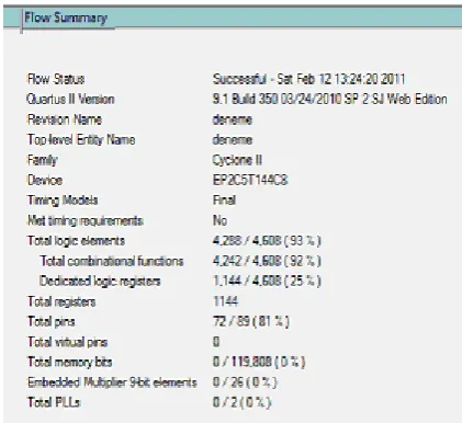
ISCUSSIONSIn conclusion, design and prototype implementation of an FPGA-based multi-functional ultrasonic generator system with two operating modes named as manual and automatic was achieved. Figure 9 shows the digital only design summary of the manual operating mode of the cleaning system. As can be seen in Figure 9, although some new functions and runtime blocks have been added to the earlier FPGA based work [2] such as power and frequency controls are employed separately, the logic capacity utilization was remained almost the same by way of the proposed modular hardware design here.
The power level control as well as the frequency control for each cleaning tank can also be adjusted independently. These flexible power and frequency controls are done by enabling the corresponding switches assigned one for each cleaning tank. Therefore enabled tanks are only controlled together if desired. It is important to note that for a common frequency and power level control case, the levels for each tank starts from its own latest set value. For instance, there are nine different power levels for this design, and when one step event on a common push button switch increases the power level of tank-1 from 5 to 6, it also increases the power level of tank-2 from level 2 to 3 at the same time. However, the tanks which are not enabled are not affected during this control event.
The design summary of the automatic operating mode is shown in Figure 10. The two-step iterative resonance frequency detection algorithm which is faster and more precise than that of the earlier work was developed and implemented for this operating mode. It can be seen that the logic capacity utilization of this mode is much higher than that of the manual operating mode.
Implementation of recapturing resonance frequency and running at resonance frequency in the form of a continuous loop provides more efficient cleaning process. Moreover, two-step frequency sweeping idea provides advantages in terms of accuracy and speed for the tracking operation. Hence, time consuming caused by sweeping the complete frequency band in detail and the error margin caused by the coarse sweeping are both reduced when compared to the authors’ earlier works published.
The photo of the completed prototype ultrasonic generator system is shown in Figure 11. The FPGA based digital control panel board, power units and mixed signal feedback circuit can be seen in this photo. Experimental works on the prototyped cleaning system for each of the manual and automatic operating modes have also been done successfully.
A similar study focusing on frequency tuning of ultrasonic transducers is reported in the literature [10]. Although it is not a real implementation, it presents a three-step frequency capturing algorithm. When compared to our study, the following differences should be highlighted. The operating frequency and frequency sweeping range is much higher than that of ours, which is between 2.02 MHz and 2.27 MHz. Therefore the target application is different since our work is focused on 48 KHz ultrasonic cleaning processes. While the finest
frequency step in [10] is 10 KHz, ours is less than 50 Hz. One other important difference is the method of sampling. [10] uses voltage sampling while our work uses current sampling, which is much more accurate way of feedback in this kind of specific application. The last important difference is related to design complexity. It is believed that using a CORDIC generator core will make the design more complex, however our proposed method is much simpler and practical.
Fig.9. Design summary of manual operating mode
Fig.10. Design summary of automatic operating mode
Copyright © 2012 IJECCE, All right reserved
Fig.11. The photo of the prototype ultrasonic cleaning generator system resulting in an easier modifications in the code and
reconfigurations even in hardware level. The advantages of FPGA- based systems are well presented in [11]. Moreover, not only our work but also some latest papers advertises FPGA usage in multiple PWM generation in power electronics area such as [12], [13], [14], [15].
A
CKNOWLEDGEMENTThis work is financially supported by Turkish Scientific and Technical Research Council of Turkey under the contract no 109E295
R
EFERENCES[1] http://en.wikipedia.org/wiki/Ultrasonic_cleaning (Visiting date
08.02.2011)
[2] A. Tangel, M. Yakut, E. Afacan, U. Guvenc, H. Sengul, “An
FPGA based multiple-output PWM pulse generator for ultrasonic
cleaning machines”, Applied Electronics International
Conference, Pilsen, Czech Republic, 2010, pp.1-4.
[3]
http://www.ctgclean.com/technologylibrary/articles/ultrasonic-cleaning-fundamental-theory-and-application/ (Visiting date
10.02.2011)
[4] Q. Peng, H. Wang, X. Su, X. Lu, “A new design of the high
power ultrasonic generator” Control and Decision
Conference,Yantai, Shandong, 2008, pp. 3800-3803.
[5] M. Yakut, A. Tangel, C. Tangel, “A microcontroller-based
generator design for ultrasonic cleaning machines”, Istanbul
University-Journal of Electrical and Electronics Engineers. Vol. 9 (1), 2009, pp. 853-860.
[6] E. Koutroulis, A. Dollas, K. Kalaitzakis,“High-frequency pulse
width modulation implementation using FPGA and CPLD Ics”, Journal of Systems Architecture, Vol. 52 (6), 2006, pp. 332-344.
[7] A. M. Omar, N. A. Rahim, S. Mekhilef, “Three-Phase
Synchronous PWM for Flyback Converter With Power-Factor
Correction Using FPGA ASIC Design”, IEEE Transactions on
Industrial Electronics, Vol. 51(1), 2004, pp. 96-106.
[8] A. Arbit, D. Pritzker, A. Kuperman, R. Rabinovici, “A DSP
controlled PWM Generator using Field Programmable Gate
Array”, Proceedings 23 rd IEEE Convention of Electrical and
Electronics Engineers in Israel, 2004, pp. 325-328.
[9] P. P. Chu, “FPGA Prototyping by VHDL Examples”, John
Wiley&Sons, 2008, pp 118-121.
[10] F. Coutard, P. Schweitzer, E. Tisserand, “Modelling of an
ultrasonic auto-controlled frequency generator in VHDL-AMS
language”, Measurement Science and Technology, Vol.
19(2008), 2008, pp. 1-9.
[11] N. Sulaiman, Z. A. Obaid, M. H. Marhaban, M. N. Hamidon, “
Design and Implementation of FPGA-Based Systems-A
Review”, Australian Journal of Basic and Applied Sciences, Vol.
3(4), 2009, pp. 3575-3596.
[12] N. K. Mohanty, R. Muthu, “A Novel Implementation of Xilinx
FPGA Based Four Switch Three Phase IGBT Inverter Fed
Induction Motor Drive Using PWM” European Journal of
Scientific Research, Vol.48 (3), 2011, pp. 424-433.
[13] D. N. Sonawane, M. S. Sutaone, B. N. Choudhari, A. Badurkar,
“FPGA Implementation of Simplified SVPWM Algorithm for Three Phase Voltage Source Inverter”, International Journal of Computer and Electrical Engineering, Vol.2 (6), 2010, pp. 1010-1017.
[14] R. Arias, H. Mediote, H. Tacca, “Flash FPGA-Based Numerical
Pulse-Width Modulator”, Advances in Power Electronics,
Hindawi Publishing Corporation, Vol.2011, Article ID 215376, 2011, pp. 1-6.
[15] W. Fu, H.B. Yu, “Using FPGA and CPLD ICs to achieve
High-frequency PWM”, Advanced Materials Research, Volumes
271-273, 2011, pp. 314-319.
A
UTHOR’
SP
ROFILEU. Guvenc
Copyright © 2012 IJECCE, All right reserved
A. Tangel
Ali Tangel received the BSc degree from Gazi University, Ankara, Turkey in 1986; and MSc degree from Hacettepe University, Ankara, Turkey in 1991; and Ph.D degree from The Pennsylvania State University, USA in 1999, respectively. He served as research assistant at Dept. of Electronics Engineering, Gazi University, Turkey from 1987 to 1993. He also served as teaching assistant in Electrical Engineering Dept., The Pennsylvania State University in 1998. Then, He served as Assistant Professor in Dept. of Electronics&Communication Engineering, Kocaeli University, Turkey until September, 2011. He is currently an Associate Professor in the same department. His research interests include Analog and Mixed-Signal VLSI Design, Field Programmable Gate Arrays (FPGAs), and Electronic Instrumentation.
M. Yakut
Mehmet Yakut, is Asst. Prof. in Dept. of Electronics
and Telecommunication, Kocaeli University.
Research interests are image and video processing, embeded medical and control applications and wireless smart sensor networks. He received Phd degree in the area of vector image compression from University of Kocaeli. He was executive director of Eureka Project based on “wireless smart fire alarm system”.