Preface
Worm gears can be produced in different ways, depending on the size of the transmission, number of gearing courses, pitch angle of worm profile, number of units produced, intended appli-cation, etc. The worm gears can be made as cylin-drical worms with globoid gears, globoid worm with globoid worm gear and globoid worm with cylindrical worm gearing [2].
There are a few types of cylindrical worms with globoid worm gear wheels and they can be divided according to the shape of the side curve of the worm tooth in frontal plane. The shape of the side of the tooth is given by the location and shape of the tool applied to produce the worm gears. In the manufacture of worm gears, tools for
their production may have shapes of cut edges, either straight or curved.
Cylindrical worms with straight tooth flank can be spiral, general, involute and concave ones. The screw is spiral when the side curve of the tooth in frontal plane is Archimedes spiral. The worm is spiral if the curve of the side of the tooth in frontal plane is Archimedean spiral.
General worms are those with linear tool cut-ting edges (generacut-ting line of the side of the tooth) located in the normal plane passing through the center of tooth gap during manufacturing.
Involute worms are those with an involute curve of the side of tooth in the frontal plane. Cy-lindrical worms that are manufactured by tools with curved cutting edges are worms with con-cave (convex) side of the tooth profiles.
research Journal
Volume 7, No. 17, March 2013, pp. 1–5
DOI: 10.5604/20804075.1036988 Research Article
Received: 2012.10.22 Accepted: 2012.12.03 Published: 2013.03.15
calculaTion of The ShaPe of Tool cuTTing edge for ProducTion
of involuTe worm
Ján Kráľ Jr.1, Ján Kráľ 2
1 Faculty of Mechanical Engineering, Centrum of Informatics, Technical University of Košice, Slovakia, e-mail:
2 Faculty of Mechanical Engineering, Department of Technologies and Materials, Technical University of Košice,
Slovakia. e-mail: [email protected]
AbstrAct
The article deals with theoretical analysis of the production of worm gears and also the calculation of the tool cutting edges for their production. Based on the design parameters of worm and worm wheel, it is possible to calculate the coordinates of the shape of the tool cutting edge. The exact calculation of the coordinates or parameters requires mathematical formulations and applying mathematical relationships we can transform the design of worm screw profile to the profile of tool. Worms of different types can be produced in various ways, e.g. with a lathe and the plane to set a tool is either axial or normal. In this article we consider their production on the lathe and tool setting in the normal plane. Axial profile of worm is a curve which is the intersection of worm surface and the plane passing through its axis, and normal profile is perpen-dicular in a selected point to worm profile. This normal profile in more accurately way characterizes the shape of the worm profile, therefore, the calculation of the shape of the tool cutting edge is designed with a tool set to the normal plane. Based on the analyses, the new computation equations were obtained, flowchart compiled and, ac-cording to a given regulation, the computer aided calculation of the coordinates can be implemented.
Worms can be roughly machined by milling cutters of disc, shank pin, hobbing types, rack-shaped cutters, slotting heads, single-bit cutters and on a lathe by shaped turning tools. Finish-ing operations are mainly performed on grindFinish-ing machines using grinding tools of shrank, straight, straight cup or disk types [1].
The shape of the side surface of the worm de-pends on the shape of the tool profile and its set -tings due to the worm to be machined. According to the shape of the side curve of the tooth of worm in frontal plane we distinguish worm gears with toothing of worm:
• spiral worms, where the shape of the side curve is Archimedean spiral,
• general worms, where the shape of the side curve is a general curve,
• involute worms where side curve is an invo-lute,
• concave worms, the shape of the side curve is the part of the circle (concaved on the side of the tooth) [4].
BaSic definiTionS for SurfaceS
of worm
The term “worm motion of point (curve, ...) in the space” means the motion composed of ro-tation with constant angular velocity around the fixed axis and translation with constant veloc -ity in the direction of this axis. This axis can be called the axis of a worm motion.
Considering the arbitrary curve in the space, under term “the worm area determined by this curve”, we understand the surface generated by worm motion of this curve around the considered axis. This axis can be denoted as the axis of the worm surface.
Under term “axial profile of worm surface” we understand the curve that is the intersection of this surface and the plane passing through its axis.
The term “the front profile of worm surface” means the curve that is the intersection of this sur-face and the plane perpendicular to this axis.
Under term “the thread of worm surface” we understand a curve which is the result of a worm motion of particular point on worm surface.
Under term “the normal profile of worm sur -face” we understand a curve that is the intersec-tion of this surface and the plane perpendicular to the thread. This definition is ambiguous. In particular cases, it is necessary to define which
thread is considered. Worm surface can be de-fined as a surface generated by worm motion of the considered profile.
equaTionS of worm Surface
To derive the equations of worm surface, con-sider a right-handed rectangular coordinate sys-tem (0, x, y, z) connected to this surface the way that the axis of the worm surface is identical to the axis z, the axial profile is lying in the plane y = 0 and the frontal section in the plane z = 0.
Considering the curve by its worm motion the corresponding worm surface is generated and can be expressed by parametric equations:
(1)
where: u – parameter.
Worm surface determined by the curve can be expressed by parametric equations:
(2)
Parameter φ is the angle of rotation around the z axis. The constant p is called the slope pa-rameter, i.e. size of translation corresponding to rotation about one radian [6]. When we denote t as the distance between corresponding generated points at worm motion about angle φ = 2π then:
or (3)
Equations of the worm surface determined by its axial profile. Consider that the axial profile of the worm surface is given (i.e. its section of plane y=0) and the parametric equations of the profile are:
(4)
where: r – parameter that defines the distance of point of profile from the axis z.
Parameter r is a given function that defines the profile from rp to rh, it is so-called foot or head radius [4].
(5)
; ; .
fronTal Profile of worm Surface
deTermined By iTS axial Profile
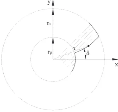
Consider a worm surface determined by its axial profile (4), i.e. surface determined by the equations (5). Its frontal profile is its section of the plane z = 0 (Fig. 2).
Each point of the frontal profile is given by parameters:
r – distance from the starting point,
δ – rotation around the z axis, where r is either a function of δ (i.e., r = r (δ), or δ is a function of r (ie, δ = δ (r)), as appropriate.
Specific point of front profile is then given by relations (see polar coordinates). Concrete point of the front profile is given by equations:
(6)
Equations of worm surface given by its front profile according to (2) will be:
(7)
According to (4) the axial profile must be:
(8)
From (8) we obtain:
or (9)
and
(10) From relations (9) and (10) we obtain:
(11) or
where: f-1 is inverse function to function f.
The normal Profile of The worm
Surface deTermined By iTS axial
Profile
Consider a worm surface determined by its axial profile (Fig. 1) i.e. surface defined by equa -tions (5). Under term “the normal plane” we un-derstand a plane passing through the x axis and perpendicular to the thread, which is wound on the pitch cylinder of radius rr in the point (rr, 0, 0). This thread is generated by worm motion of this point and has parametric equations [3]:
(12)
The point (rr, 0, 0) corresponds to the value of parameter . Normal vector of this plane is, therefore, identical withthe contact vector t
of this thread at point (rr, 0, 0) and thus:
φ (13) Fig. 1. Generating line of involute
By substitution of derivations (12) we obtain: (14) Subsequently, considering the unit normal vector, the normal plane can be expressed:
, where:
(15)
considering:
(16)
Normal profile of worm surface will be the curve which is the intersection of the surface (5) and the plane (15). We can mathematically ex-press it with equations (5) and (15) excluding the parameter φ. By substitution (5) into (15) we ob-tain:
(17) For each fixed value of parameter , the (17) is a transcendent equation for the unknown parameter . This equation can be solved only approximately, e.g. using Newton’s method. If we calculate approximate angle φ for a given , the corresponding point of normal
profile, lying on a cylinder of radius r is given by relations (5). If we introduce the tool coordinate system (0n, xn, yn) in the corresponding normal plane the way that and axis yn completes this sys-tem as rectangular and also clockwise; then, the point of normal profile will have the coordinates
, as follows:
(18)
where: (x, y, z) are calculated coordinates of point of normal profile in the coordinate system (0, x, y, z).
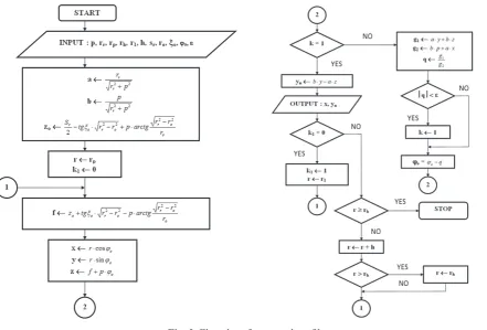
Flowchart for calculation of the shape of tool cutting edge for production of the worm for nor-mal profile of involute worm gearing
Summary
In this paper the formulas for calculation of the shape of tool cutting edges for production of worms are given, assuming the tool setting in the normal plane. The proposed equations allow the automated calculation in any available program-ming language. The coordinates of the points of tool cutting edge shape are calculated and based on them the tools will be sharpened. Considering
the possible technological deviation of tool pro-file in the production, it is recommended the cal -culation are rounded to more decimal places for production for more accurate profiles. The shape of the tool cutting edge is designed for tool setting in the normal plane.
reference
1. Janáč A. at al. 2004. Technológia obrábania. STU, sig: 11330, Bratislava.
2. Kráľ J. 1994. Výpočet, konštrukcia a výroba rezných nástrojov pre závitovkové prevody
pomo-cou výpočtovej techniky. Habilitačná práca. TU Košice, p. 102.
3. Kráľ J. 1988. Výskum určovania dotykových
kriv-iek a záberových pomerov pri spoluzábere závi-tovkových súkolesí: Návrh a realizácia riadiaceho systému pre nástrojovú brúsku KON 250 CNC. TU, SjF, Košice, p. 22.
4. Kráľ j., řehoř, j., Spišák E., Kráľ J. Jr. 2009. Tech-nologické a informačné činitele obrábania. Košice. 5. Kráľ J. at al. 2007. Programovanie NC strojov. 1.
vyd. TU, SjF,. Košice, p. 181.