INTRODUCTION
One of the major problems in automotive in-dustries become apparent in the form of pump-ing losses durpump-ing the intake of atmospheric gasses and discharge of exhaust gases in Spark Ignition (SI) engines. There are different methods to over -come and solve these losses and to optimize the aspiration and discharge of exhaust gases. In ad-dition, the European Union has signed the Kyoto protocol [10] to reduce the greenhouse and an-thropogenic emissions. Therefore, the control of these emissions was added to the numerous straints that vehicle manufacturers have to con-form to. Consequently, to overcome the problems that were explained above, one main solution that industries have been used is Variable Valve Tim-ing (VVT). As the Figure 1 shows, VVT allows the cam profile to change at diverse loads and speeds. The controlling parameters for VVT are
the intake and exhaust valve event durations, the overlap and the position of these events relative to the piston motion [16, 2].
Different attempts have been made to devise the methods of developing and applying VVT to improve the engine performance. One of early study by Luria [15] derived that enforcing varia-tions in the IVC could be advantageous. Fon-tana [7] utilized detailed computer simulations of physical traits to indicate that in both single and multi-cylinder engines, late IVC (LIVC) can di-minish the pressure tension caused by manifold pulsations. If some of the new charge is pumped backward, a more uniform residual gas distribu-tion between the cylinders will be achieved. In the article by Tuttle [18], the authors reported that LIVC will not increase the fuel consump-tion. This is contrary to the results of paper [19] in which LIVC caused a 4-cylinder 4-stroke en-gine to improve full-load enen-gine efficiency by
Investigating the Effects of Variable Valve Timing
on Spark Ignition Engine Performance
Sepehr Bapiri
1*, Cem Sorusbay
21 Automotive Engineering, Faculty of Mechanical Engineering, Istanbul Technical University, Istanbul, Turkey 2 Mechanical Engineering, Faculty of Mechanical Engineering, Istanbul Technical University, Istanbul, Turkey * Corresponding author’s e-mail: [email protected]
ABSTRACT
In this study, a prototype four-stroke spark ignition engine with four cylinders (two valves per cylinder), with and without turbocharger, as well as variable valve timing system to adjustment of variable valve duration has been
investigated. This study covers the effects of intake valve opening (IVO), Intake valve closing (IVC), exhaust
valve opening (EVO) and exhaust valve closing (EVC) angles on engine performances and fuel economy. The calculations of engine performance were carried out using the 1-Dimensional simulation with AVL BOOST
soft-ware. The effects of different valve timing strategies and a combination of them from simulations were analyzed and compared with the reference fixed valve timing cases. It was shown that substantial improvements in fuel con
-sumption and performance can be achieved. The improvements of Indicated Specific Fuel Con-sumption (ISFC)
are remarkable in turbocharged models. Furthermore, we can see the noticeable improvements in torque and power in the naturally aspirated engine.
Keywords: spark ignition engine; variable valve timing; turbocharger; AVL BOOST; engine performance; fuel consumption.
Volume 13, Issue 2, June 2019, pages 100–111
https://doi.org/10.12913/22998624/103917
Research Journal
Accepted: 2019.04.0911%. Although late EVO (LEVO) decreases the exhaust gas pressure and requires work for pump-ing out, Hara [9] found that it could improve volumetric efficiency if the exhaust gas is fully pumped out by the piston because no residual gas will remain inside. Kang [12] equipped a diesel engine with a pneumatic inlet valve controller which acts using a nonlinear mean value model under wide-gap dynamic conditions and the re-sults show some improvement. Benson [3] dem-onstrated that a 4-cylinder 4-stroke diesel engine can benefit from LIVC with regard to fuel sav -ings, volumetric efficiency and residual gas dis -charge. Similarly, Saunders [17] showed that an overall VVT approach can improve fuel economy in diesel engines. Fiorenza [6] concluded that a continuous VVT can increase the output torque. Caufield [4] reported that VVT can decrease the fuel consumption in small spark-ignition (SI) engines through accurate fluid path simulations. The VVT was shown to be of even greater ben-efit for auto ignition diesel engines by Cao [13], who discussed its effect on gas composition and combination. Ghazal and Borowski investi-gated the effect of different water mass flow rates and air/fuel ratio on the SI engine emissions and performance as well [8].
The objective of this study is to model and optimize the VVT system design and operation for maximum system benefits and to derive the valve timing strategies for the VVT mechanism. The system should be simple in construction, op-eration and easily adaptable to the base engine. In order to obtain the closest results to the real life, all the geometrical, chemical and physical data pertaining to the engine should be entered as close to the actual values as possible. Some engine pa-rameters may be confidential to the company, they should be applied appropriately near the na-ture of a spark ignition engine’s characteristics. The base engine was simulated in 1D virtual En-gine simulation tool software AVL BOOST. This programme has advanced models for accurately
predicting the engine performance, acoustics and the effectiveness of exhaust gas after treat -ment devices [11]. The performance of developed simulation model was compared with the actual performance of the base engine. The simulation model was then further used to study the effects of variable valve timing at different engine speeds (low to high) on the engine performance (espe-cially effective torque and effective power) and fuel consumption. In addition, the VVT systems have an effect on the exhaust gas emissions; how -ever this isssue was not investigated in the present study. For this purpose, the models were inves-tigated in two modes; first, when just one valve port is shifted and second, when more than two ports are shifted at the same time to gain the best results. Although the variable valve lift also has a significant influence on the performance of the engine [5, 1, 13], we focused on different combi -nations of intake and exhaust valve timing tried in 1D simulation model to study their effects on the effective performance of the engine.
MODELLING
Layout of 4-cylinder engine without turbocharger
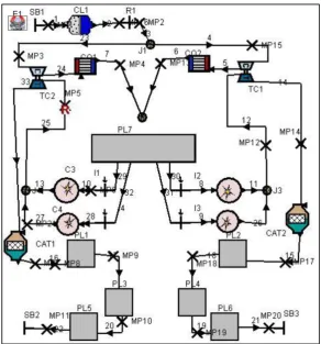
As Figure 2 indicates, a 4-stroke engine con-sisting of 4 cylinders, 2 valves per cylinder that have two catalysts was used for simulation. This model has 26 pipes as connections and 3 bound-ary systems. Table 1 shows the main specifica -tions of the engine.
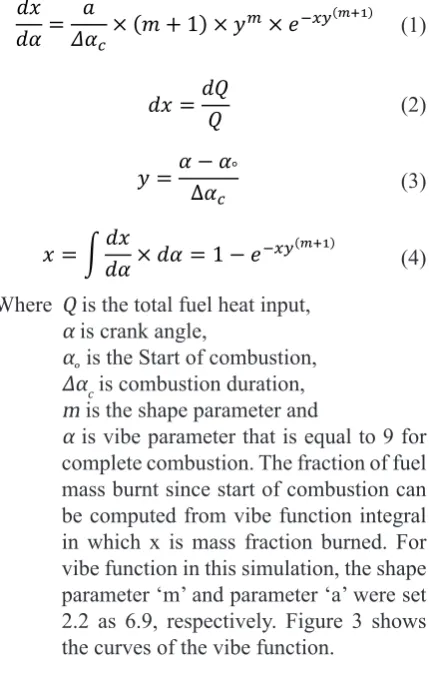
on the amount of fuel inside the cylinder and A/F ratio. On the basis of total heat supplied, AVL BOOST calculates actual heat input per degree crank angle. The vibe function can calculated from equations (1–4) as follows:
𝑑𝑑𝑑𝑑 𝑑𝑑𝑑𝑑 =
𝑎𝑎
𝛥𝛥𝑑𝑑𝑐𝑐× (𝑚𝑚 + 1) × 𝑦𝑦
𝑚𝑚× 𝑒𝑒−𝑥𝑥𝑥𝑥(𝑚𝑚+1) (1)
𝑑𝑑𝑑𝑑 =𝑑𝑑𝑑𝑑𝑑𝑑 (2)
𝑦𝑦 =𝛼𝛼 − 𝛼𝛼∆𝛼𝛼 °
𝑐𝑐 (3)
𝑥𝑥 = ∫𝑑𝑑𝑥𝑥𝑑𝑑𝑑𝑑 × 𝑑𝑑𝑑𝑑 = 1 − 𝑒𝑒−𝑥𝑥𝑥𝑥(𝑚𝑚+1) (4)
Where Q is the total fuel heat input, α is crank angle,
α˳ is the Start of combustion,
Δαc is combustion duration,
m is the shape parameter and
α is vibe parameter that is equal to 9 for complete combustion. The fraction of fuel mass burnt since start of combustion can be computed from vibe function integral in which x is mass fraction burned. For vibe function in this simulation, the shape parameter ‘m’ and parameter ‘a’ were set 2.2 as 6.9, respectively. Figure 3 shows the curves of the vibe function.
In valve port specification for inner valve seat diameter of intake and exhaust valves, we set 23.4 mm and 25.4 mm, respectively. The surface areas corresponding to the ports for intake and exhaust valves are 17000 mm2 and 16000 mm2,
respectively.
Layout of 4-cylinder engine with a turbocharger
As Figure 4 shows, this 4-stroke engine is the same as the previous engine but equipped with two turbochargers and two intercoolers. For steady state engine performance, a simpli-fied turbocharger model was used for the simula -tion. Within this model ,the dynamics of the tur-bocharger (i.e. the variation of the turtur-bocharger speed) are not considered. Furthermore, the tur-bocharger efficiency is kept constant during the Figure 2. 1D engine cycle simulation model
Table 1. Specifications of engine
Engine Four stroke SI
Displacement 1.787 Litre
Bore 82 mm
Stroke 84.6 mm
No of cylinders 4
Compression ration 12
Speed 1000–7000 rpm
Intake valve duration 268 degrees
Figure 4. 1D turbocharged engine cycle simulation model
engine cycle. As many test calculations have proven, this model provides good accuracy for steady state engine calculations. It is very conve-nient to work with this model, as only the mean values for the compressor efficiency, the turbine efficiency, and the mechanical efficiency of the turbocharger must be specified. This reduces the required input dramatically in comparison to the full turbocharger model where entire compressor and turbine maps must be defined. Since turbine performance maps are rarely provided by turbo-charger manufacturers , this simplified solution is usually the only alternative. All the parameters including boundary conditions, valves specifica -tions, vibe function and heat transfer are the same as previous model. The differences between the two models are in the compression ratio, so in the turbocharged model, the compression ratio is 10. Table 2 shows the specifications of the turbo -charged engine.
RESULTS AND DISCUSSION
Conventional engines (without VVT)
After preparing the models and building all the connections between the elements and enter-ing necessary data, the models are ready to run .As mentioned previously, it is very important to
enter the initial conditions and boundary condi-tions and all other relevant data as close to the real case as possible. However all entered data is valid only for one situation. When the oper-ating mode of the engine is changed, A/F ratio, start of injection and combustion duration will change too. These have to be specified for each case. However, the boost case explorer enables to define many of the parameters as variable. For running the model, first of all, the Naturally As -pirated (NA) engine was tested that was used for evaluating the results of the engine equipped with VVT. First of all, for running the both models, six cases were tested: 1000–2000 rpm (low end), 2000–4000 rpm (moderate) and 4000–6000 rpm (high end). For each speed, we extracted the fol-lowing main parameters of the engine: effective power, effective torque and indicated specific fuel consumption (ISFC). Table 3, Table 4 and Figure 5 to Figure 7 show the results and trends of these parameters for diverse speeds for both the NA Engine and TC Engine, respectively. The results show that the trend of changes in effective power and torque are the same for both engines. In the NA engine, it was observed that at 4000 rpm, the effective torque is in maximum limit and af -ter 4000 rpm the torque hold a downward trend. The amount of power hold an increasing trend. In addition, there is a sharp decrease in the indi-cated specific fuel consumption from 1000 rpm to 2000 rpm. Past 2000 rpm, the fuel consumption maintains a small upward trend. In the TC engine, At 1000 rpm, the effective torque is in maximum limit and after that it shows a downward trend. For the effective power as figure 6 shows, the amount of power exhibits an increasing trend. There is a sharp increase in the indicated specific fuel con -sumption from 2000 rpm to 7000 rpm. Further-more, the optimum situation for ISFC happened when the engine works at 2000 rpm.
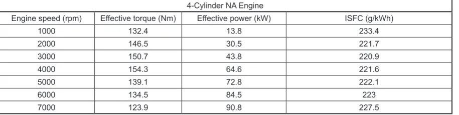
Table 3. Result of the NA engine when the valve ports were fixed
4-Cylinder NA Engine
Engine speed (rpm) Effective torque (Nm) Effective power (kW) ISFC (g/kWh)
1000 132.4 13.8 233.4
2000 146.5 30.5 221.7
3000 150.7 43.8 220.9
4000 154.3 64.6 221.6
5000 139.1 72.8 222.1
6000 134.5 84.5 223
7000 123.9 90.8 227.5
Table 2. Turbocharged engine specifications
Engine Four stroke SI
Displacement 1.787 Litre
Bore 82 mm
Stroke 84.6 mm
No of Cylinders 4
Compression Ration 10
Speed 1000–7000 rpm
Intake Valve Duration 268 degrees
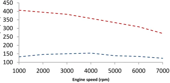
Figure 7. Indicated specific fuel consumption vs engine speed – NA engine-TC engine Table 4. Result of the TC engine when the valve ports were fixed
4-Cylinder TC Engine
Engine speed (rpm) Effective torque (Nm) Effective power (kW) ISFC (g/kWh)
1000 406.6 42.6 232
2000 394.9 82.7 229
3000 382.7 120.2 237.7
4000 358.5 150.2 242.9
5000 333.8 174.8 251.4
6000 309.1 194.2 259.9
7000 270.1 198 267.9
Figure 5. Effective torque vs engine speed – NA engine-TC engine
Results of VVT for each valve
In the next step, all parameters were kept constant, except the Intake Valve Opening (IVO) angle. This angle were altered between -20 to 20 degree (some of the simulations cases done in period of (-25 to 25)). After that the influence of Intake Valve Closing (IVC) was investigated as same as IVO. Finally, we repeated those works for Exhaust Valve Opening (EVO) and Exhaust Valve Closing (EVC). Having used these meth-ods to observe the effect of each port, we ran the systems in which all the ports-timing were modi-fied between -20 to 20 crank angle degrees and worked at the same time. Consequently, these results enabed us to gain a better understanding about the function of not only each valve but also the condition when the all ports work simulta-neously. Tables 5 and 6 show the percentage of improvements in each valve at diverse speeds of both engines for torque-power and ISFC respec-tively, which will be demonstrated as follows:
Intake valve opening effect
In the NA engine, we see a minor improve -ment in effective torque and power when the
intake valve open earlier than normal time (EIVO strategy) and this improvement decreases in the engine’s high speeds. In contrast, by increasing the speed, the indicated specific fuel consumption improves. In the engine equipped with a turbo-charger, the result show that we have a signifi -cant refinement (up to 4%) in torque and power with the same strategy, specially in high speeds of engine. Moreover, in low speeds with shifting +10 degree of crank angle, we can achieve up to 0.73% of improvement in ISFC.
Intake valve closing effect
In the NA engine, there are two strategies for IVC in different speeds; from low speed to mid-range speeds, early intake valve closing strategy (EIVC) was used and can be achieved up to 7.11% of improvement for effective torque and power; however, this improvement is minor (0.2%) for ISFC. For higher speeds, the late intake valve closing strategy (LIVC) has better result for both engine performance and fuel consumption. For turbocharged engine, the greatest impacts can be achieved by EIVC strategy in low engine speeds and are about 4.83% for torque and power as well as 0.38% for ISFC.
Table 6. Percentage of improvements of isfc for both engines at different speeds
Type of engine Engine speed (rpm)
1000 2000 3000 4000 5000 6000
IVO NA engine 0.098 0 0.01 0 0 0.55
Turbocharged engine 0.58 0.52 0.19 0.19 0.27 0.66
IVC NA engine 0.2 0.04 0.07 0.26 0.2 0.46
Turbocharged engine 0.38 0.14 0.21 0.33 0.37 0.67
EVO NA engine 1.2 0.77 0.73 0.59 0.25 2.2
Turbocharged engine 0.57 0.07 0 0.1 0 0.38
EVC NA engine 0.74 0.25 0.01 0.07 0 0
Turbocharged Engine 0.72 0.27 0.45 0.85 0.49 0.56
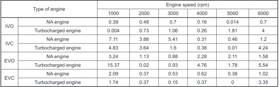
Table 5. Percentage of improvements of effective torque and effective power for both engines at different speeds
Type of engine Engine speed (rpm)
1000 2000 3000 4000 5000 6000
IVO NA engine 0.39 0.48 0.7 0.16 0.014 0.7
Turbocharged engine 0.004 0.73 1.06 0.26 1.81 4
IVC NA engine 7.11 3.88 5.41 0.31 0.46 1.2
Turbocharged engine 4.83 3.64 1.6 0.38 0.01 4.24
EVO NA engine 3.24 1.13 0.88 2.28 2.11 1.58
Turbocharged engine 15.37 0.02 0.93 4.76 1.78 5.54
EVC NA engine 2.09 0.37 0.53 0.62 0.38 1.02
Exhaust valve opening effect
In the investigation of EVO, in the Engine without a turbocharger, the most significant changes can be seen in fuel consupmtion: in low rpms the fuel consumption can be improved up to 1.2% by late exhaust valve opening (LEVO) strategy. Moreover, in this strategy the amount of power and torque can be increased by 3.24% in low speeds. In the turbocharged engine, with early exhaust valve opening we better results can be obtained, specially in torque and power these improvements are significant in low to mid-range speed, reaching 15.7% improvements. In high speeds by shifting the valves to LEVO strategy, the torque and power were raised by 5.54% . Un-fortunately, the improvements of ISFC in EVO are not significant for both engines.
Exhaust valve closing effect
By altering the exhaust valve closing timing for both engines, it can be observed that the best strategy for optimizing the power, torque and ISFC is late exhaust valve closing (LEVC), ex-cept in high speeds of NA engine where the im -provements are minor.
Possible strategies when 4 valves changed simultaneously
There are 8 different strategies for VVT, including:
1. Late intake valve closing (LIVC). 2. Early intake valve closing (EIVC). 3. Late intake valve opening (LIVO). 4. Early intake valve opening (EIVO). 5. Early exhaust valve opening (EEVO). 6. Late exhaust valve opening (LEVO). 7. Early exhaust valve closing (EEVC).
8. Late exhaust valve closing (LEVC).
The effects of possible VVT strategy com -binations in different speeds were analysed by simulations and combined to find the most ad -vantageous strategies and correct amount of overlaps to obtain significant benefits in improv -ing the engine performance parameters and fuel consumption. Tables 7 and 8 indicate the possible combination of strategies in NA engine for gain -ing maximum improvements of effective power-torque and indicate specific fuel consumption, respectively. According to the results, in rmps between low to mid-range speeds, to achieve the greatest improvements in effective power and torque and smooth idling at low rpm, we ought to decrease the valves overlap duration to 30 degrees because the valve overlap in our conventional en-gine is 56 degrees of the crank angle,. Thus, this operation was based on the degree of advance on both IVC and EVC, and the degree of delayed IVO and EVO. In contrast, by combining LIVC and EEVO at high speeds in the NA engine, the engine wants to increase the valve overlapping period to provide better discharge of the burned
Table 8. Combination of strategies for improvements of ISFC in NA engine
Engine speed (rpm)
NA engine ISFC
EIVO LIVO EIVC LIVC EEVO LEVO EEVC LEVC
1000 × ×
2000 × × ×
3000 ×
4000 ×
5000 × ×
6000 ×
Table 7. Combination of strategies for improvements of eff. power nad eff. torque in NA engine
Engine
speed (rpm) EIVO LIVO EIVC NA engine torque and powerLIVC EEVO LEVO EEVC LEVC
1000 × × × ×
2000 × × × ×
3000 × × × ×
4000 × × × ×
5000 × ×
gases. As the Table 8 indicates, the most effective strategy for reducing fuel consumption is to open the exhaust valve later than normal degree, which causes greater expansion and increases the pump-ing losses at the beginnpump-ing of the exhaust stroke.
As Table 9 shows, advancing the overall valves timing is better for low to mid-range en-gine speeds in power and torque improvements. This is because the valves are closing a little sooner. The intake closes at or near the piston at BDC for the start of the compression stroke. This strategy is significant at low rpm, because the in -take air velocity is low and easily affected by the changes in the direction of piston movement in the engine. Almost as soon as the piston gets to BDC on the intake stroke, the air cannot escape as the pistons start to move to the TDC on the compression cycle. Better results were obtained at high speeds when the overall cam timing was retarded because the air can continue to flow into and fill the cylinder, even after the piston has be -gun to travel up the cylinder bore. This can allow
a boosted engine to exceed the optimum volumet-ric efficiency, if even by a small amount. Table 10 indicates the acceptable combination of strate-gies for decreasing the fuel consumption. When it comes to the possible and correct strategies in TC engines to reduce fuel consumption, it should be noted that due to complex treatment of VVT on turbocharger, it is harder to investigate ISFC in the TC engine than in the NA engine. When the intake manifold pressure is higher than the atmosphere pressure, an increased valve overlap (retarded the exhaust valves, and/or advanced the intake valves), increases the cylinder charge flow. Consequently, it causes higher temperature of gases which are better at spooling the turbine and help spinning it turbine faster. In contrast, by increasing overlap duration, we observed an increasing trend in ISFC too. Accordingly, we should advance the exhaust valve, and retard the intake valve.
The overall best results, based on improving the Effective Torque, Effective Power and ISFC
Table 11. Percentage of improvements for overall conditions
Type of engine Engine speed (rpm)
1000 2000 3000 4000 5000 6000
NA engine Eff. torque and power 10.8% 8.82% 7.97% 3.51% 3.05% 3.06%
ISFC 3.21% 1.82% 0.73% 0.59% 0.29% 1.21%
TC engine Eff. torque and power 7.07% 5.74% 3.21% 3.96% 4.43% 5.61%
ISFC 3.7% 1.7% 3.29% 2.87% 3.66% 2.28%
Table 10. Combination of strategies for improvements of ISFC in TC engine
Engine speed (rpm)
TC engine ISFC
EIVO LIVO EIVC LIVC EEVO LEVO EEVC LEVC
1000 × × ×
2000 × ×
3000 × ×
4000 × ×
5000 × ×
6000 × × ×
Table 9. Combination of strategies for improvements of eff. power nad eff. torque in TC engine
Engine speed (rpm)
TC engine torque and power
EIVO LIVO EIVC LIVC EEVO LEVO EEVC LEVC
1000 × ×
2000 × × ×
3000 × × ×
4000 × ×
5000 × ×
a) b)
c)
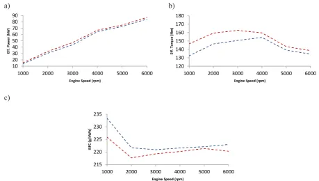
Figure 8a. Effective Power vs Engine Speed in NA Engine -VVT -Fixed Valve Figure 8b. Effective Torque vs Engine Speed in NA Engine -VVT -Fixed Valve
Figure 8c. ISFC vs Engine Speed in NA Engine -VVT-Fixed Valve
a) b)
c)
Figure 9. Effective Power vs Engine Speed in TC Engine -VVT-Fixed Valve Figure 9b. Effetive Torque vs Engine Speed in TC Engine -VVT-Fixed Valve
for both engines, are presented in Table 11. The results show that for both NA and TC engines, the greatest changes were made in the low engine speeds. In comparison with the results in Table 5 in which we shifted just one port, in most cases we have better result by combinations of strate-gies except in the improvements of torque and power in the TC engine at low engine speed. Fig-ures 8a,b,c and Figure 9a,b,c indicate the trend of improvements when the all the ports shifted at the same time for the NA and TC engines, respective -ly. It can be observed that in the NA engine, from low to mid-range engine speeds, the VVT has sig-nificant effects on all parameters in comparison to high speeds, except from 5000 to 6000 rpm, where we see a sudden improvement in ISFC. In the TC engine model, the results show that at low engine speeds the VVT has remarkable ef-fects on indicated specific fuel consumption. It is interesting that at moderate engine speeds in the TC engine model, the efficiency of VVT is at the minimum level.
CONCLUSIONS
This study was concerned with optimiz-ing VVT systems in the NA and TC engines for investigating the most effective strategies for improving the engine performance and fuel economy at full load condition. In addition, pos-sible combinations of diverse strategies were developed to study the parameters. “Variable” ability in valve timing can be used to better suit the aspiration capability of an engine, resulting in an improved fuel efficiency, improved torque characteristics, increased horse power and im-proved engine smoothness. In this research, the function of the valves is studied both indi-vidually and in combination. In the NA engine, variations of IVC have the largest effects on the power and torque changes at low to moderate engine speeds (7.11% at 1000 rpm and 5.41% at 3000 rpm). Second to IVC, variation of EVO, especially when the exhaust valve opens later than the normal, the crank angle degree has the greatest effect. For instance, the improvements of power and torque at 5000 rpm are 2.11% in EVO shifting and 0.46% in IVC shifting. Un-like torque and power, the total improvements of ISFC by shifting of each valve are more re-markable in the turbocharged model, except in EVO. In the application of a turbocharger, lesser
overlap duration is more acceptable due to the pressure of exhaust valve which is higher than in the NA engine. As a result, more overlap can allow backflow near TDC with pollution and heating of the intake charge. Combining two or more strategies (with more than two valve ports shifted simultaneously), better results can be ob-tained for the performance of both the NA and TC engines. For example, the average improve-ments of torque and power in NA engine are 3.06 for the first mode (just one port shifted) and 6.2% for the second mode (more than two ports shifted). In the second mode, the improvements of ISFC for both engines are much higher than in the first mode. The authors observed that it is hard to apply a single specific algorithm to gain a suitable improvement in both power and fuel consumption especially for the TC engines. The effect of VVT strategies on the exhaust emissions which has not been within the scope of this work can be investigated as a part of after-treatment analysis. Coupling this simulation with the CFD analysis of combustion process and an Exhaust Gas Recirculation (EGR) system can provide ac-curate results in future work.
Acknowledgements
The authors would like to thank AVL Tur-key for the support and providing an aca-demic license for AVL BOOST software to Istanbul Technical University.
REFERENCES
1. Anderson M.D., Tsao T.C. and Levin M.B. Adap-tive lift control of an electrohydraulic camless val-vetrain system. In: Proceedings of the American Control Conference, IEEE, Vol. 2, 1998, 955–956. 2. Bapiri S., Chaghaneh O. and Ghomashi H. Vari-able valve timing scheduling in a 4-stroke internal
combustion cylinder utilizing artificial neural net -works. Advances in Science and Technology Re-search Journal, 11(3), 2017, 114–121.
3. Benson R.S., Annand J.D. and Baruah P.C. A simu-lation Model Including Intake and Exhaust Systems for a Single Cylinder Four-Stroke Cycle Spark Igni-tion Engine. Int. J. Mech. Sci., 17, 1975, 97–124. 4. Caufield S,, Rubenstein B., Martin J.K., et al.
A comparison between CFD predictions and
5. Diana S., Iorio B., Giglio V. and Police G. The ef-fect of valve lift shape and timing on air motion and
mixture formation of DISI engines adopting differ
-ent VVA actuators. SAE Paper No. 2001–01–3553.
6. Fiorenza R., Pirelli M., Torella E. et al. Variable swirl and internal EGR by VVT application on small displacement 2 valve SI engines: an intel-ligent technology combination. In: FISITA 2004 world automotive congress. May 2004, 23–27. 7. Fontana G., Galloni E. Variable valve timing for fuel
economy improvement in a small spark-ignition en-gine. Journal of Applied Energy, 86, 2009, 96–105. 8. Ghazal O.H., Borowski G. Use of water injection
technique to improve the combustion efficiency of
the spark-ignition engine: A model study. Journal of Ecological Engineering, 20(2), 2019, 226–233. 9. Hara S., Nakajima Y., Nagumo S. Effects of intake
valve closing timing on SI engine combustion.
SAE Technical Paper, No 850074, 2015.
10. https://unfccc.int/resource/docs/convkp/kpeng.pdf 11. http://www.avl.com/web/ast/boost
12. Kang J.M. and Grizzle J.W. Dynamic control of a SI engine with variable intake valve timing.
Inter-national Journal of Robust and Nonlinear Control,
13(5), 2003, 399–420,
13. Kreuter P., Heuser P., Reinicke-Murmann J., Erz R., Peter U. and Böcker O., Variable valve actua-tion: Switchable and continuously variable valve lifts. SAE transactions, 112(3), 2003, 112–123. 14. Cao L., Zhao H., Jiang X. and Kalian N. Under
-standing the Influence of Valve Timings on Con -trolled Auto-Ignition Combustion in a Four-Stroke Port Fuel Injection Engine. Journal of Automobile Engineering, 219(6), 2005, 807–823.
15. Luria D., Taitel Y., and Stotter, A. The Otto–Atkin -son Engine anew Concept in Automotive
Econo-my”, SAE Technical Paper, No 820352, 2002.
16. Ma T.H. Recent advances in variable valve timing. In Automotive Engine Alternatives. Springer US, 1987, pp. 235–252.
17. Saunders R.J., Rabia S.M. Part Load Efficiency in
Gasoline Engines. Institution of Mechanical Engi-neers, Combustion Engines Group, 1986.
18. Tuttle J.H. Controlling engine load by means
oflate intake-valve closing. SAE Technical Paper, No. 800794, 2008.
![Figure 1. Actual valve timing for a four-stroke spark ignition engine [3]](https://thumb-us.123doks.com/thumbv2/123dok_us/8805484.1774338/2.595.153.441.75.164/figure-actual-valve-timing-stroke-spark-ignition-engine.webp)