Available Online at www.ijpret.com 9
INTERNATIONAL JOURNAL OF PURE AND
APPLIED RESEARCH IN ENGINEERING AND
TECHNOLOGY
A PATH FOR HORIZING YOUR INNOVATIVE WORK
DYNAMIC ANALYSIS OF SINGLE POINT CUTTING TOOL USING FEM”
AKSHAY GANESH KHANDE
Department of Mechanical Engineering, BABASAHEB NAIK COLLEGE OF ENGINEERING, Pusad (M.S.)
Accepted Date: 15/03/2016; Published Date: 01/05/2016
\
Abstract: Finite element analysis method is used to study the effect of different rack angles & nose radius on the force exerted on the tool during cutting. In present study, the two different rake angles & nose radius are studied to find out the variation in values of Von-misses stress for the specified applied forces. As we increase the rake angle then the value of Von-misses stress goes on decreasing. Finding the comparative study of software and analytical results for rack angles 30 & 50 and nose radius 0.3 mm & 0.5 mm on von-misses stresses and total deflection of cutting edge.
Keywords: Single point cutting tool, Ansys, FEM
Corresponding Author: MR. AKSHAY GANESH KHANDE
Access Online On:
www.ijpret.com
How to Cite This Article:
Available Online at www.ijpret.com 10
INTRODUCTION
Among various machining parameters, tool nose radius has a significant contribution to the cutting dynamics and the stability of a machining process. Nose radius is a major factor that affects surface finish of the machined surface. A larger nose radius produces a smoother surface at lower feed rates and a higher cutting speed. Large nose radius tools have, along the whole cutting period, slightly better surface finish than small nose radius tools.
For single point cutting tool most important angle is back rake angle. The back rake angle affects the ability of the tool to shear the work material and form the chip. It can be positive or negative.
Finite Element Method (FEM) based modeling and simulation of machining processes is continuously attracting researchers for better understanding the chip formation mechanisms, heat generation in cutting zones, tool-chip interfacial frictional characteristics and integrity on the machined surfaces. Predicting the physical process parameters such as temperature and stress distributions accurately plays a pivotal role for predictive process engineering of machining processes. The cutting forces vary with the tool angles, feed and cutting speed. Knowledge about the forces acting on the cutting tool may help the manufacturer of machining tool to estimate the power requirement. Tool edge geometry is very important, because its influence on obtaining most desirable tool life and surface integrity is extremely high.
Available Online at www.ijpret.com 11
Fig.1- Tool Geometry
1. Shank: – It is main body of tool. The shank used to grip in tool holder.
2. Flank: – The surface or surface below the adjacent of the cutting edge is called flank of the
tool.
3. Nose: – It is the point where side cutting edge & base cutting edge intersect.
4. Cutting edge: – It is the edge on face of the tool which removes the material from work
piece. The cutting edges are side cutting edge (major cutting edge) & end cutting edge (minor cutting edge).
5. Tool angles: - Tool angles have great importance. The tool with proper angle, reduce
breaking of tool, cut metal more efficiently, generate less heat.
6. Back Rake Angle: - The angle between face of the tool and a line parallel with the base of the
tool, measured in a perpendicular plane through the side cutting edge is called back rake angle.
7. Side Rake Angle: - The angle between the face of the tool and a line parallel with the base of
Available Online at www.ijpret.com 12
Sample Analytical Calculation
For conducting the test on specimen material following data was considered for first set of readings with 3 degree rake angle & 0.3 mm nose radius
The following data from the orthogonal cutting test is available,
Rake Angle = 30
Chip Thickness Ratio = 0.5
Nose radius =0.3 mm
Uncut Chip Thickness = 0.3 mm
Width of Cut = 3 mm
Yield Shear Stress of Work Material = 380 N/mm2
Mean Friction Coefficient on Tool Face = 0.65
Determine the
1. Cutting force
2. Radial force
3. Normal force on the tool
4. Shear force on the tool.
Solution:-
Shear angle β = 𝑡𝑎𝑛−1 (rcosα/1−rsinα)
Shear angle β = (0.5cos3/1−0.5sin3)
β = 270
μ = tanϒ
Available Online at www.ijpret.com 13 To find shear stress,
Ʈ = sinβ*Fs/A
Fs = Ʈ𝑥A1/sinβ = 380 * 3 * 0.3sin27
Fs = 750 N
Fs = FCos𝜃 = Fcos (β+ϒ−α)
F = Fscos (β+ϒ−α) = 750cos (27+33−3)
F=1376N
Cutting force, Fz = Fcos (ϒ−α) = 1376cos (33−3) = 1191.6N
F = √Fz2+Fx2
Radial force, F𝑥= √F2+Fz2 = √ (1376)2− (1191.6)2
F𝑥=688N
Normal force on the tool,
N = Fzcosα−Fxsinα = 1191.6cos3−688sin3
N=1154N.
Results
Shear force (Fs) = 750 N
Cutting force (Fz) = 1191.6 N
Radial force (Fx) = 688 N
Normal force on tool (N) = 1154 N
Available Online at www.ijpret.com 14
Observation Table
Table No.1:- Analytical forces and stresses at different sets of rake angles
Software Modeling and Analysis
Fig.2: - Single point cutting tool in CATIA.
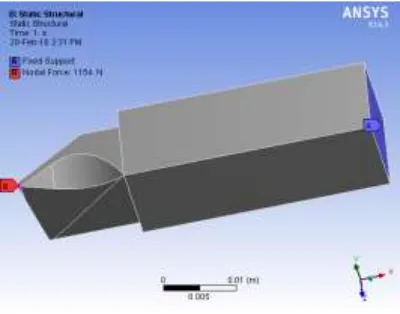
ANSYS Boundary Condition and Results for STATIC Loading
Fig.3- Boundary Conditions
No. of
Samples
Rake angle (degree)
Nose radius (mm)
Normal Force (N)
Cutting Force (N)
Compressive stress
(N/mm2)
1. 3 0.3 1154 1191.6 3.61
2. 3 0.5 1923.5 1986.6 6.01
3. 5 0.3 1096.3 1154.3 3.42
Available Online at www.ijpret.com 15
Fig.4- Meshed Product
Available Online at www.ijpret.com 16
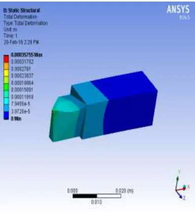
Fig.6- Total deformation at 1154N force
ANSYS Observation Table for STATIC loading
Table 2- ANSYS Result
Rake angle (degree)
Nose radius (mm)
Normal Force (N)
Cutting Force (N)
Compressive stress
(N/mm2)
Deform-ation
in Normal
Directi-on (mm)
3 0.3 1154 1191.6 2.00 0.03
3 0.5 1923.5 1986.6 3.80 0.125
5 0.3 1096.3 1154.3 2.20 0.075
Available Online at www.ijpret.com 17
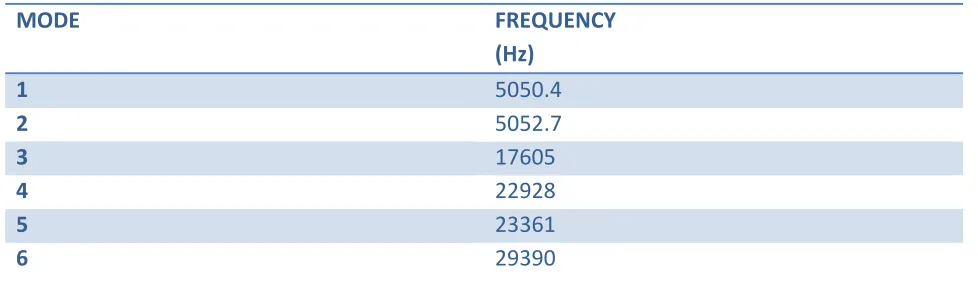
ANSYS Results for MODAL Analysis
MODE FREQUENCY
(Hz)
1 5050.4
2 5052.7
3 17605
4 22928
5 23361
6 29390
Table 3- Frequency of Single Point Cutting Tool
CONCLUSION
1. As the single point cutting tool is one of the major part of machining process, to increase tool efficiency and performance along with its life. It is very necessary to analysis it.
2. It is observed that as depth of cut increases, the von-misses stresses developed in the tool increases which are the main reason of tool failure.
3. With the help of calculated tool life, it is possible to determine the range of optimal cutting parameters with maximum tool life.
4. Variation in nose radius and rake angle has a predominant influence on tool life.
5. Tool shows better performance with 5 degree rake and 0.3 mm nose radius with minimal tool wear and there by better tool life.
6. It is observed that with increasing nose radius tool life decreases, it is less for 0.5 mm nose radius as compare to 0.3 mm.
7. The wear of tool with 0.5 mm nose radius is less than 0.3 mm nose radius and the stress in tool is lower with 0.3mm node radius for 3 degree rake angle tool.
8. The wear of tool with 0.5 mm nose radius is less than 0.3 mm nose radius and the stress in tool is lower with 0.5mm node radius for 5 degree rake angle tool.
Available Online at www.ijpret.com 18 10. The Harmonic analysis of above mentioned single point cutting tool is done to determine the variation of vibration when this tool is subjected to different forces which acts on it while machining operation is done.
REFERENCES
1. S. H. Rathod, Mohd. Razik, “Review Study on Finite Element Analysis of Single Point Cutting Tool”, International Journal of Engineering Research and Development e-ISSN: 2278-067X, p-ISSN: 2278-800X, www.ijerd.com Volume 9, Issue 1 (November 2013), PP. 11-14.
2. Deepak Bhardwaj, B. Kumar Research Scholar, “Study and Analysis of Single Point Cutting Tool under Variable Rake Angle” International Journal of Scientific and Innovative Research 2014; 2(1): 150-157, P-ISSN 2347-2189, E- ISSN 2347-4971.
3. PROF. MAHESHWARI PATIL, DR. R. J. PATIL, “ Finite Element Analysis Study of cutting forces of geometry of Single point cutting tool” INTERNATIONAL JOURNAL OF PURE AND APPLIED RESEARCH IN ENGINEERING AND TECHNOLOGY ISSN: 2319-507X, Volume 3 (10): 49-64