Available Online at www.ijpret.com
541
INTERNATIONAL JOURNAL OF PURE AND
APPLIED RESEARCH IN ENGINEERING AND
TECHNOLOGY
A PATH FOR HORIZING YOUR INNOVATIVE WORK
SHADOW MATTING AND COMPOSITING WITH MULTIPAL AND REFLECTED LIGHT
SOURCES
UMESH S.THAKARE1, AJAY B. GADICHA2
1. Scholar of Computer Science and Engineering Department, P.R. Pote College of Engineering Amravati, Sant Gadage Baba Amravati University, Amravati , Maharashtra, India.
2. Assistant Professor of Information Technology Department , P.R. Pote College of Engineering Amravati, Sant Gadage Baba Amravati University, Amravati , Maharashtra, India.
Accepted Date: 27/02/2014 ; Published Date: 01/05/2014
\
Abstract: Mobile cloud computing is an emerging technology to improve the quality of mobile services. Mobile Cloud Computing (MCC) which combines mobile computing and cloud computing, has become one of the industry buzz words and a major discussion thread in the IT world since 2009.Mobile cloud computing is an emerging technology to improve the quality of mobile services. Mobile cloud computing has revolutionized the way in which mobile subscribers across the globe leverage services on the go. The mobile devices have evolved from mere devices that enabled voice calls only a few years back to smart devices that enable the user to access value added services anytime, anywhere. MCC integrates cloud computing into the mobile environment and overcomes obstacles related to performance (e.g. battery life, storage, and bandwidth), security (e.g. reliability and privacy). In this article, we provide a comprehensive study to lay out existing mobile cloud computing service models and key achievements, and present a new user-centric mobile cloud computing service model to advance existing mobile cloud computing research.
Keywords: Matt, Composite, Intensity, Reflection, Penumbra, Sharpen
Corresponding Author: MR. UMESH S.THAKARE
Access Online On:
www.ijpret.com
How to Cite This Article:
Umesh Thakare, IJPRET, 2014; Volume 2 (9): 541-550
Available Online at www.ijpret.com
542
INTRODUCTION
Shadow matting and compositing technique are used to produces the image of the object this technique is very useful for produces special effect of object. During the Matting procedure the object produce the image in background of the plane according to the light source, so the foreground element of the image can be extracted from film or video in the sequences. In Compositing method we can extract the foreground element which is placed over the background images.
In this paper we are going to display the shadow matting and compositing with multiple light sources, here we can explain the theoretical concept of the shadow matting and compositing with multiple light sources, if we are apply multiple light source on the single object then there is producing the multiple Shadow on the background of the plane of object. The darkness of object is totally depends on the intensity of the light source. Also we are explaining the reflection of the light source and produce the multiple shadows on the plane of object.
For creating realistic special effects matting and compositing are very important. Matting is when cutting out or isolating a foreground object from a scene and compositing when the cut out object is combined with a new background to create composited image. Shadows are an important part of this as they provide visual and perceptual cues for depth, shape, contact, movement and lighting.
In latest paper the methods such as blue-screen matting require a single-color background. To get realistic looking shadows from this method it is usually required to build a rough model of the scene for actors to cast shadows on.
MATERIAL AND METHOD
The main approach is to extract shadows from the foreground plates using luma keying or blue-screen matting. These techniques provide a better approximation to the correct shadow characteristics.
Shadow Matting
In this section, we develop our shadow compositing equation and traditionally, matting and compositing operations are based on the compositing equation.
C = αF + (1 −α)B--- (1)
Where, α is the opacity of the foreground
Available Online at www.ijpret.com
543
F is the foreground color
C is a composite color.
B is the background color
The Shadow Compositing Equation
To determine an appropriate model for shadow compositing, we treat the problem within a simplified lighting framework. If we further assume no inter reflections, then we can model the observed color C at a pixel as:
C = S + βI--- (2)
Where , C is a composite color.
S is the shadowed color,
I is the reflected contribution of
β is the visibility to that light
Source.
Let L be the color of a pixel when not in shadow. Substituting I =L − S into Equation (2) and rearranging, we obtain the shadow compositing equation,
C = βL + (1 −β)S.--- (3)
S = min Cf and L = max Cf---(4)
β =((C − S) ・ (L − S) )/ ||L – S||2 --- (5)
Shadow Compositing
To perform shadow compositing, we require the lit and shadow images L’ and S’ corresponding to the novel background scene.
C’= βL’+ (1 −β)S’--- (6)
Available Online at www.ijpret.com
544
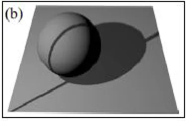
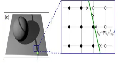
Figure 1. Illustration of the principle and details of geometric shadow scanning. Point Q isthe point on the reference plane that lies behind point P along ray V
Computed as the first time the pixel color goes below a threshold halfway between its min and max values, Imin and Imax. In the reference plane region, we can then determine the shadow line for frame f of scan s, ls,f = (ms,f , bs,f ), by linearly interpolating between neighboring pixels with shadow times less than and greater than f (shown as black and white dots, respectively) and then fitting a line through the interpolated points.
Figure 2. 3D Renderings of the two individual shadow lines.
Available Online at www.ijpret.com
545
Figure 3. Shadow line fitting Reflection and Refraction of Light
Reflection
a. Use the planar mirror.
b. Send a single ray of light, non-perpendicular into the mirror (incident ray)
c. Trace the position of the mirror, the incident ray, and the reflected ray.
d. Draw a normal (line perpendicular to the mirrors surface) to the mirror surface at the point the light strikes the mirror.
e. Measure the angle of incidence (angle between the normal and the incident ray).
f. Measure the angle of reflection (angle between the normal and the reflected ray).
Refraction
a. Use the optically transparent sample with two parallel surfaces.
b. Send a single ray of light, non-perpendicular to the surface of the block.
c. Trace the position of the sample, incident ray, and refracted ray.
d. Draw a normal at the point the light entered or exited the sample’s two parallel surfaces.
e. Complete the ray that passed through the optical sample.
f. Measure the angle of incidence and refraction on each of the parallel surfaces.
Total Internal Reflection
a. Use the transparent triangular shaped sample (or rectangular glass plate).
Available Online at www.ijpret.com
546
c. Trace the position of the sample, incident ray and exiting ray. Note the point of reflection in the optical sample (See sample data).
d. Complete the path for the rays that were internal in the optical sample
e. Construct a normal at the point of reflection within the block.
f. Measure the angle between the normal and the reflected ray.
Figure 4. Reflection/refraction of light with shadow
RESULT AND DISCUSSION
Available Online at www.ijpret.com
547
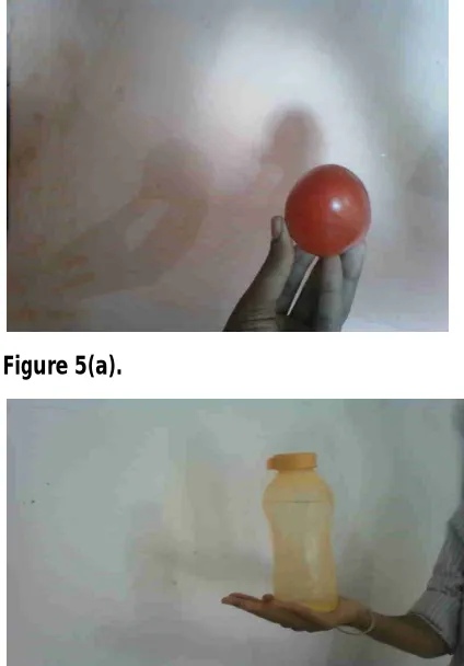
harder penumbra. Finally, we would like to extend the operating range of the shadow matting and compositing equations, and experiments suggest that at least some extensions are possible. For instance, assuming the source and target backgrounds are Lambertian and geometrically similar, we have been able to matte and composite plausible shadows cast by multiple light sources without taking separate images for each light source, as shown in Figure.
Figure 5(a).
Figure 5(b).
Available Online at www.ijpret.com
548
Figure 5.a, 5.b, 5.c Shadows cast by multiple light sources without taking separate images for each light source
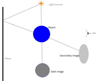
Now for the discussion purpose we are taking the multiple light source (two) focused on the original object the intensity one of the light is higher than another so that the shadow of the original object is dark in the plane and extract image on opposite displacement of the plane while secondary light source apply on the main object, secondary light source has less intensity than the main light source so the shadow of the secondary light source is light dark in color.
Figure 6. Shadow matting and compositing with multiple light sources
Available Online at www.ijpret.com
549
Figure 7.Shadow matting with reflected light source
Our method can be extended to transfer shadows of multiple light sources
CONCLUSION
We have introduced a physically-based shadow matting and compositing method. Our approach has many advantages over previous approaches to shadow extraction and compositing. First, it can extract both the photometric and geometric information required for shadow compositing from natural (planar) scenes. Second, it can cast multiple shadows on producing multiple light sources on the object. Third, we can get the natural multiple shadows by reflection of the light source and focused on the object. Fourth, it can cast shadows onto complex geometry without manually modeling the scene. Because we use the same camera to capture our warping function as we do to capture the images of the scene itself, we avoid the difficulties of having to accurately register an independently reconstructed model to our image.
ACKNOWLEDGMENTS
I am greatly indebted to my supervisors Prof. Ajay B. Gadicha, P. R. Patil, College of Engineering and Technology Amravati (Maharashtra) for their invaluable technical guidance and moral support during writing technical paper. I am also thankful to Prof. A.M. Bainwad Prof. in Shri Guru Gobind Singhaji Institute of Engineering and Technology, Nanded (An Autonomous Instituted in Maharashtra) for his suggestions during work and clear the all difficulties while coming in work. I would like to thank all my friends for their feedbacks during our informal discussions and other embedded group members for their cooperation and support.
REFERENCES
1. Shadow Matting and Compositing TNCG13 - SFX - tricks of the trade, paper 3 Erik Johansson-Evegard Tuesday 8th December, 2009.
2. Shadow Matting and Compositing Tung Yu Chuang, Dan B Goldman, Brian Curless, David H. Salesin, Richard Szeliski. ACM SIGGRAPH 2003. San Diego, California. 2003.
Available Online at www.ijpret.com
550
4. Shadow Matting and Compositing Yung-Yu Chuang, Dan B Goldman, Brian Curless, David H. Salesin, Richard Szeliski University of Washington, Microsoft Research, Industrial Light and Magic.
5. New Models and Methods for Matting and Compositing Yung-Yu Chuang A dissertation submitted in partial fulfillment of the requirements for the degree of Doctor of Philosophy University of Washington 2004.
6. COMPUTER GRAPHICS for Sciencetistist and Engineer, R.G.S. Asthana N. K Sinha.