Volume 2, Issue 5, October 2014
27
Bug Tracking System
1Krishan Kumar, 2Amandeep
1, 2Assistant Professor
1, 2 Department of computer science and Engineering
1, 2 Guru Jambheshwar University of Science & Technology, Hisar, India
Abstract—Bug Tracking for Improving Software Reliability (BTS) is a systematically approach that can be
useful to staffs and the administrators in any organization. Bug Tracking System gives the facility to assign the jobs in the organization and also permits the supervisors to way the bugs consumed by the employee for their specific job. A report group ability is sustained in BTS that allows the supervisors to analyses whom are those services by the worker are utilized and those which are not used. This system can help administrators for Bug estimation each project or application. The tool helps teams to files their Bugs and analyses. This application goals at the construction of a Bug Tracking System. This system will be accessible to all developers. Its skill agrees developers to motivation and creating the database chart.
Index Terms— Bug, User, Experts, Administrator, HTML, JSP
I.INTRODUCTION
Bug Tracking android application is the simple approach which enables to search the bugs. It nor only identifies the bugs but support the overall figures related bugs noticed. This approach ensures the user of it who desires to recognize almost a afford information concerning the well-known bug. By means of this approach none of bug unstable in the settled request [5].
The designer improves the assignment as per consumer constraint. In the stimulating stage, the tester will recognize the bugs. Whenever the tester meetings a number of bugs he modify the bug id and evidence to administrator. The tester reports to both the project supervisor and designer [3]. The bug information in the administrator record is available for both. When a client send appeal for a product to its development administrator is accountable for modify a user to a Bug Tracking System and allot jobs to the users [1].
The bug report is mailed to the project manager and the developer as soon as the bug is identified. This makes that no error will go unfixed because of poor communication [7]. It makes ensures that anyone who needs to know about a bug can learn of it soon after it is reported.
II.EXISTING SYSTEM
The bugs that are identified by the tester in the software testing phase are reported to the Project Manager and developer through simple shared lists and emails [10]. Most of the companies share this information through a document called “Defect report” [2]. This procedure is error-prone and there is ample chance of leaving some bugs unfixed and ignored as there is no particular tracking system in place. The team involved in the software development lifecycle must be aware of the status of each and every bug reported. The existing system fails to fulfill this requirement thus it affects the productivity and accountability of every member of the team [4].
III. LIMITATIONS IN
E
XISTINGS
YSTEM Information recovery is a huge process.
Time-consuming.
Lack of group of the records may prone to data loss due to inadvertent removal of records.
No safety because the records are perceptible to the users.
Statement generation will be a large job. .IV.PROPOSED SYSTEM
Volume 2, Issue 5, October 2014
28
status of the bug. Bugs can be created and updated with ease. Specific user accounts to control the access and maintain security are incorporated into the application. Bug tracking system which is implemented on Java provides an overview of standards of coding of the developers involved. Employee accountability can be tracked and analyzed on daily basis by using report generation option. This web-based business application is a great tool for assigning and tracking issues and tasks during software development and any other projects that involve teams of two or more people [10].
Privacy of documents.
Guarantee data accuracies.
Proper manage of the higher administrator.
Minimize manual data entry.
Minimum time required.
Better Service
Advantages over the Existing system
The performance is enlarged due to the well-organized databank.
Safety is improved.
Less-time conusemed in output.Workings
Bug Tracking System is totally worked on Java Server Pages (JSP), JavaScript, MySQL, and HTML. JSP, a Java-based technology, it enjoys all of the advantages that the Java language provides with respect to development and deployment. JSP runs on major web platforms. The client makes a request via an HTTP. The web server receives the request and sends it to the Servlets/JSP engine. If the Servlets/JSP is not loaded, the web server will load it into the JVM and execute it. The web server returns a response to the Client. JavaScript [1]. A scripting language is a lightweight programming language which is basically responsible for
Creating Dynamic Pages.
JavaScript was designed to add interactivity to HTML pages
Read and Write HTML Elements.
Validate Data.
Bug Tracking Modules
A module of a software project is nothing but a group of programs working together to achieve a common objective.
Administrator
The administrator module control the access of all modules in system. Administrator generates the plan and assign the goal to the Technical team, assigned bugs are based on the precedence. Administrator can inform the staff and control to the particular job documents. Output records are based on the Expert’s statement suggestion.
Sub-module of the Administrative module:
View Bugs
:
Administrator can view all bugs updated by the user and assign them to the technical experts.Configure Experts
:
Bugs are assigned by the administrator based on their priority to the technical expert.Add Expert
:
Administrator can add technical experts according to their capability.
Logout
: In this, once the user clicks on Log out First the session variable is killed and then the
system is redirected to the login page.Technical Expert
:
a Technical expert can log in into the system and view all the bugs registered
in the database by users. Technical expert comment to the bug. These comments can also be used as a solution to the bug. By adding a comment to the particular bug, bug detail is updated to that bug.
User Module
Volume 2, Issue 5, October 2014
29
Sub-module of User module:
Report a Bug: User can report a new bug into the system with its attribute such as product, environment, type, bug description. In product, the user can describe the product of the bug and in the environment, there is a description of the operating system of the user. The type describes the type of bug i.e. it is a database bug, hardware bug, operating system bug, software bug etc. The user can also provide an additional description of the bug in the bug description.
View Status
:
User can the status of the reported bug. It tells if the bug is still open, being worked on or fixed.V.
B
UGT
RACKINGSYSTEM
DIAGRAM
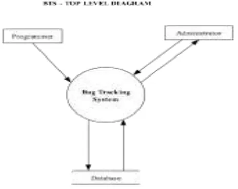
These diagram shows the graphical representation of the "flow" of data by an info system, modeling its process features. A information flow events is always used as a initial stage to develop an outline the system without going into great detail, which can later be explained.
Figure 1. Context Free Diagram Figure 2. Login Process
Top Level DFD
Volume 2, Issue 5, October 2014
30
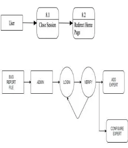
Figure 3. Logout Process Figure 4. Administrative DFD
Login Process and Logout Process:
In fig. 2 show the login process of Bug Tracking System that show us the how a user and admin login to the
System. The first user enters their username and password in the login box and after that java page verifies the username with the database that it actually registered or not. If username match with the database username then it verifies the password with the database. This process going on until it matches with all the entries of the database, if not found then it shows invalid user and password. The same process is going with admin. Fig. 3 shown the login process of Bug Tracking System that show us the how a user can Log out from the system. User logout the system then it closes the session and it redirects homepage.Admin Level DFD, Expert Level DFD and User Level DFD
Volume 2, Issue 5, October 2014
31
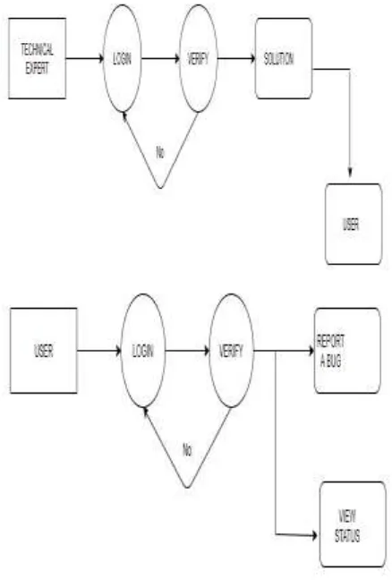
Figure 5. Technical Expert DFD Figure 6. User Level DFD
In the technical expert level, DFD in fig. 5 shown in the rectangular box, the expert has to log in with the correct id and password and confirm that it is an expert user. The experts view the list of bugs and give the solution and then they directly submitted to the user. In the User level DFD diagram the user is shown in fig. 6 the rectangular box, the user has to log in with the correct id and password and confirm that it is a user. The user can report the bug and can view the status of the bug.
VI.
U
SEC
ASE DIAGRAM FORB
UGT
RACKINGS
YSTEM(BTS)
Use case diagram is the primary form of system/software requirements for a new software program underdeveloped. Use cases specify the expected behavior (what), and not the exact method of making it happen. Use cases once specified can be denoted as both textual and visual representation [2]. A key concept of use case modeling is that it helps us design a system from the end user's perspective. It is an effective technique for communicating system behavior in the user's terms by specifying all externally visible system behavior. A use case diagram is usually simple. It does not show the detail of the use cases:
It only summarizes some of the relationships between use cases, actors, and systems.
It does not show the order in which steps are performed to achieve the goals of each use case.
In the diagram there are three actors are present the actors are different users of the system
Admin
Expert
Student
Volume 2, Issue 5, October 2014
32
VII.
E
NTITY-
R
ELATIONSHIPD
IAGRAM FORBTS
An Entity Relationship (ER) Diagram is a type of flowchart that illustrates how “entities” such as people, objects or concepts relate to each other within a system [1]. ER Diagrams are most often used to design or debug relational databases in the fields of software engineering, business information systems, education and research [8]. Also known as ERDs or ER Models, they use a defined set of symbols such as rectangles, diamonds, ovals and connecting lines to depict the interconnectedness of entities, relationships, and their attributes.
Figure 7. Use Case Diagram for BTS Figure 8. Entity-Relationship Diagram for BTS
VIII.
C
ONCLUSION ANDF
UTUREE
XPANSION:
It is not easy process to develop a system that fulfill all the necessities of the user. User requirements retain varying as the application is being castoff. Some of the upcoming improvements that can be enhanced the overall approach are:
Based on the imminent safety problems, safety can be upgraded.
Attendance record module may be added
The enhanced sub-adminstrator module can be added
REFERENCES
Volume 2, Issue 5, October 2014
33
[3] Y. Sharma and A. Sharma “Comparative Study of the Bug Tracking Tools”, International Journal of Advanced Research in Computer Science and Software Engineering,Volume 5, Issue 3, pp. 530-536,
March 2012.
[4] Y. Yorozu, M. Hirano, K. Oka, and Y. Tagawa, “Electron spectroscopy studies on magneto-optical media and plastic substrate interface,” IEEE Transl. J. Magn. Japan, vol. 2, pp. 740–741, August 1987 [Digests 9th Annual Conf. Magnetics Japan, p. 301, 1982.
[5] https://www.mysql.com.
[6] E. F. Miller, “Introduction to Software Testing Technology,” Tutorial: Software Testing & Validation Techniques, Second Edition, IEEE Catalog No. EHO 180-0, pp. 4-16.
[7] http://www.flyspray.org/,”Flpspray”, Retrieved on 15-December-2014 at 1730Hrs. [8] https://creately.com/diagram/example/ilgqlcv32/uer%20case%20diagram.