______________
*Corresponding author
E-mail address: [email protected] Received July 16, 2019
707
J. Math. Comput. Sci. 9 (2019), No. 6, 707-725 https://doi.org/10.28919/jmcs/4223
ISSN: 1927-5307
PERIODIC FIRINGS IN NEURONS WITH EXTERNAL SINUSOIDAL APPLIED CURRENT
AVINITA GAUTAM1 AND ANUPAM PRIYADARSHI2,*
1DST-CIMS, Institute of Science, Banaras Hindu University, Varanasi-221005, India 2Department of Mathematics, Banaras Hindu University, Varanasi-221005, India
Copyright © 2019 the author(s).This is an open access article distributed under the Creative Commons Attribution License,which permits unrestricted use, distribution, and reproduction in any medium, provided the original work is properly cited.
Abstract: The distinct qualitative behavior exhibited by neuron at externally applied current stimuli is well known in the Hodgkin-Huxley model (HH model). The resting state and periodic firings in neuron correspond to solutions of the HH model having stable fixed points and unstable fixed point (periodic solutions through Hopf bifurcation points). The one-parameter bifurcation with respect to externally applied current stimuli suggests a periodic window between two stable fixed point solutions in the HH model. The externally applied sinusoidal current stimuli generate periodic firings at very low current and a large periodic region is observed. The generations of limit cycles and possible chaotic behavior in the HH model is explored through numerical simulations extensively.
1. INTRODUCTION
The network of neurons in the brain is very complex and study about its dynamics is also very
complicated. A human brain consists of approximately 1011 neurons [1]. The neuron is like a
signal converter since it receives stimulus via dendrites at the synapse and transmits through the
axon to other neurons [2]. This process continues as the firing of the action potential. A sufficient
input is required for firing of action potential because below that threshold values no firing of the
action potential is possible [3]. This period of no action potential is called the refractory period
[2,4].
The cell membrane has a lipid structure which is completely stable from inside and outside.
These are ion channels inside the cell which allow the specific type of ions to pass through it.
When ions pass across the cell membrane, it creates a potential difference between inside and
outside of the cell membrane. Therefore the cell membrane can behave as a capacitor. The
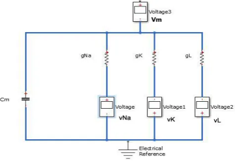
behavior of neurons depends on voltage-dependent ionic channels [5]. Hence Hodgkin and
Huxley proposed a model by an equivalent circuit.
FIGURE 1. An electrical equivalent circuit for cell membrane
According to Ohm’s law, the current through a conductor between two points is directly
proportional to the voltage across the two points. Using the voltage-clamped method
across the cell membrane. For the different ion channels (Na, K and leakage ions), the transverse
current is given as follows
( ) , (1)
i i m i
I =g V −G where i=Na K and L
Kirchhoff’s current law states that the sum of all currents in a closed system equals to zero.
J 0 (2)
j
I = for j
The ionic current for sodium, potassium, and leakage ions are considered at maximum
corresponding conductance which is given as
3
( )
Na Na Na
I = −g m h V−V
,
4
( )
K K K
I = −g n V −V
, and IL= −g V VL( − L)
Hodgkin-Huxley model of a cell membrane is important to model for the study of nonlinear
dynamics. It is highly nonlinear ODEs [6, 7, 8, 9, 10] and given by system four differential
equations (system 3) and six voltage-dependent coefficients (system 4) as follows:
3 4
[ (( 65) ) (( 65) )
(( 65) ) ] /
( )(1 ) ( ) (3)
, ,
0.1(25 ( 65)) / (exp((25 ( 65)) / 10) 1) 4 exp( ( 65) / 18)
0.07 exp( ( 65) / 20) (4)
1 / (1 exp(30 (
Na Na K K
L L x x m m h h dV
g m h V V g n V V
dt
g V V I C
dx
V x V x
dt
where x m n h
V V V V V = − + − − + − − + − + = − − = = − + − + − = − + = − +
= + − +65)) / 10))
0.01(10 ( 65)) / (exp(10 ( 65)) / 10) 1) 0.125 exp( ( 65) / 80)
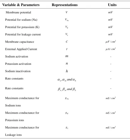
TABLE 1. Notations of Variables and parameters
Variable & Parameters Representations Units
Membrane potential V mV
Potential for sodium (Na) VNa mV
Potential for potassium (K) VK mV
Potential for leakage current VL mV
Membrane capacitance C 2
/
F cm
External Applied Current I A cm/ 2
Sodium activation m -
Potassium activation n -
Sodium inactivation h -
Rate constants
h m n and
, -
Rate constants
h m n and
, -
Maximum conductance for Sodium ions
Na
g 2
/
mS cm
Maximum conductance for Potassium ions
K
g 2
/
mS cm
Maximum conductance for Leakage ions
L
g 2
/
mS cm
The system (3) and (4) are so complex that they are mathematically intractable. Hence, extensive
2. PRELIMINARIES
If the neuron is at rest then there is no transmission of information within or in between neurons. In
the following subsections we describe the voltage time series and the effects of external stimuli
when it is constant and when it is periodic specifically sinusoidal:
No Stimulus to neuron
(a) (b)
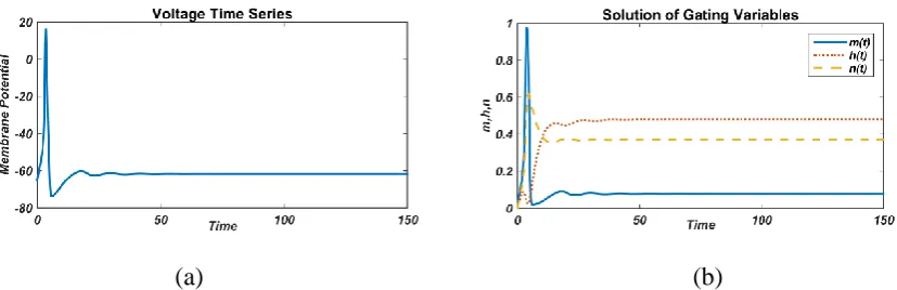
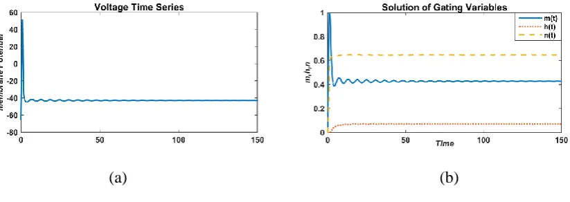
FIGURE 2. Responses of membrane potential (left) and gated variable (right) without an external current (I=0 µA/cm2)
The equilibrium state is followed by a single spike when there is no external stimulus given to
neurons (Fig. 2). Since the system is very complex so at all initial conditions, it always gives a
single spike. In this manuscript we are analyzing the effect of external current, so firstly constant
external current is applied to the system (3) and behavior has been observed.
Constant Stimulus
(a) (b)
FIGURE 3: Responses of membrane potential (left) and gated variable (right) with a constant external current value,
As the external current is increased to some positive value (say 5 µA/cm2) then it has been
observed that new disturbance in voltage is arising with very low amplitude. But immediately it
goes back to the equilibrium state (Fig. 3).
(a) (b)
FIGURE 4: Responses of membrane potential (left) and gated variable (right) with a constant external current value,
I=8.8 µA/cm2
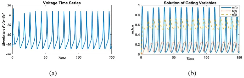
When the external current is increased to value I=8.8 µA/cm2, then it has been found that smooth oscillations occur but it disappears after 150 milliseconds (Fig. 4).
For the external current values, I=50 µA/cm2, continuous oscillation with high spike has been
observed for membrane potential and gating variables (Fig. 5). For sodium activation gated
variable (m), spikes are very high as compared to potassium activation gated variable (n) and
sodium inactivation gated variable (h).
(a) (b)
FIGURE 5: Responses of membrane potential (left) and gated variable (right) with a constant external current value,
But as the external current is increased up to I=100 µA/cm2, the amplitude of spikes decreased
as compared to initial spike but the oscillations go on and not disappear in the case of membrane
potential (Fig.6). But for the gated variables, the amplitude of spike decreases very little as
compared to membrane potential (Fig. 6).
(a) (b)
FIGURE 6: Responses of membrane potential (left) and gated variable (right) with a constant external current value,
I=100 µA/cm2
However, when the external current is increased to the value I=160 µA/cm2 then it has been
observed that after a single spike again oscillations disappear within 100 millisecond time period
for both membrane potential and gated variables (Fig. 7).
(a) (b)
FIGURE 7: Responses of membrane potential (left) and gated variable (right) with a constant external current value,
Therefore, it has been observed that for constant external current neurons behave in two ways
such as stable and oscillatory in the case of constant stimulation. Now for better understanding, we
have explored the behavior of neurons for varying external current that is when the external current
becomes a function of time.
Sinusoidal Stimulus
Now, an external current is being varied by a sine function with period 2 that is I=asint and
sin 2
I=a twith period 1 (Fig. 8).
(a) (b)
FIGURE 8: Graph of external current with respect to time I=asint (left) and I=asin 2t (right)
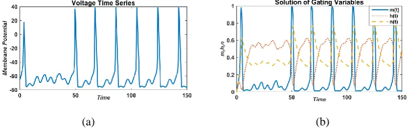
With varying external current, we have analyzed the behavior of the HH model and found that it
shows chaotic behavior for membrane potential with high spikes (Fig. 9(a)). In case of gating
variables, the behavior is also chaotic but spikes of sodium activation (m) are high as compared to
sodium inactivation (h) and potassium activation (n) for lower amplitude a=5 (Fig. 9(b)).
(a) (b)
FIGURE 9: Responses of membrane potential (left) and gated variable (right) with a sinusoidal external current, I=5
As we increase the value from 5 to 50, we have found a change in the behavior of the system. It
shows double periodic in both the case of membrane potential and gating variables (Fig. 10).
(a) (b)
FIGURE 10: Responses of membrane potential (left) and gated variable (right) with a sinusoidal external current,
I=50 sin (t) µA/cm2
For higher values of a system shows continuous oscillations with high spikes in both the cases
of membrane potential and gating variables with high spikes (Fig. 11).
(a) (b)
FIGURE 11: Responses of membrane potential (left) and gated variable (right) with a sinusoidal external current,
But for the value, a=150 spikes of membrane potential are low as compared to figure 11,
although it shows continuous oscillations for both membrane potential and gating variables (Fig.
12).
(a) (b)
FIGURE 12: Responses of membrane potential (left) and gated variable (right) with a sinusoidal external current,
I=150 sin (t) µA/cm2
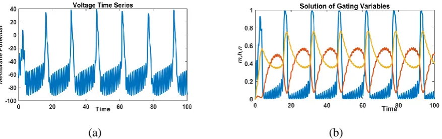
Now we are changing the frequency of sinusoidal current asI=asin(2 ).t In this case, we have
found a continuous periodic solution for both membrane potential and gating variables for lower
and higher values of a (Fig. 13). We can clearly observe from zoom picture of the behavior of
membrane potential (Fig. 13(a)) and gating variables (Fig. 14) that the solutions are periodic.
(a) (b)
FIGURE 14: Magnified picture of figure 13 (responses of gating variables with a sinusoidal external current, I=5 sin (2t) µA/cm2)
Different behavior has been observed for higher values of a. This shows that system (3) exhibits
continuous periodic solutions for the applied external current given byI =asin(2 ).t
(a) (b)
3. MAIN RESULTS
It has been observed in the above section with the help of time series analysis that model
behaves differently for different values of externally applied current. Bifurcation will occur at
equilibrium points of the system when the externally applied current is injected into the neurons
[10]. Since the system is very complex so we will study the model analytically for external current
0
I= . Stability of models can be analyzed easily with the help of equilibrium points. Let
1 1, 1 1 ( , , )
E= v m h n be the equilibrium point of the model (1) which obtained by equating right-hand
sides of the system (1) equal to zero.
Now we have Jacobian matrix after linearization of the system (1) as [11]:
11 12 13 14
21 22 23 24
31 32 33 34
41 42 43 44
(5)
f f f f
f f f f
J
f f f f
f f f f
= Where, 3 4 11
Na K L
g m h g n g
f C + + = − 2 12
3gNam h V( VNa)
f C − = − 3 13 ( ) Na Na
g m V V
f C − = − 3 14
4g n V VK ( K)
f C − = − 21 2
(2 m exp(- v/18 - 65/18))/9 + (m - 1)/(10(exp(- v - 40)/10 - 1)) + (6) (exp(- v - 40)(v/10 + 4)(m - 1))/(10(exp(- v - 40)/10 - 1) )
f =
22 (v/10 + 4)/(exp(- v - 40)/10 - 1) - 4exp(- v/18 - 65/18) f =
23 0
f =
, f24=0
31 (7 exp(- v/20 - 13/4)(h - 1))/2000 - (h exp(- v - 35))/(10(exp(- v - 35)/10 + 1)^2)
32 0
f =
33 - (7 exp(- v/20 - 13/4))/100 - 1/(exp(- v - 35)/10 + 1) f =
34 0
f =
41
2 (3 n exp(- v/80 - 13/16))/2000 + (n - 1)/(100 (exp(- v - 55)/10 - 1)) + (exp(- v - 55) (v/100 + 11/20) (n - 1))/(10 (exp(- v - 55)/10 - 1) )
f =
42 0
f =
, f43=0
44 (v/100 + 11/20)/(exp(- v - 55)/10 - 1) - (3exp(- v/80 - 13/16))/25 f =
And the characteristic equation of matrix J with is given as:
4
1 2 3 4 0 (7)
a a a a
+ + + + =
1 11 22 33 44
,
( )
where
a = − f + f +f + f
2 11( 22 33 44) 22( 33 44) 33 44 12 21 13 31 14 41 (8) a = f f + f + f + f f + f +f f −f f −f f −f f
3 12 21 33 44 13 31 22 44 14 41 22 33 11 22 33 44 11 22 33 44
( ) ( ) ( )
( ) ( )
a f f f f f f f f f f f f
f f f f f f f f
= + + + + +
− + − +
4 11 22 33 44 12 21 33 44 13 22 31 44 14 22 33 41 a = f f f f − f f f f −f f f f − f f f f
According to Rourth-Hurwitz Criterion, roots of equation (7) have negative real roots, if
2 2 1 0, 1 2 , 4 0 1 2 3 3 1 4 a a a c a and a a a a +a a
.
Otherwise, roots have non-negative real parts.
-0.3789 0.0000 0.0000 -610.8728 0.0000 -2.2198 0 0
(9) -0.0000 0 -0.0412 0
0.0121 0 0 -0.1115
A =
The characteristic polynomial of matrix A is given by
4+ 2.75143+ 8.63412+16.8527+0.6799=0 (10)
1 2 3 4
, 2.7514, 8.6341, 16.8527, 0.6799
where a = a = a = a =
According to Routh- Hurwitz Criterion, since
1
1 2
4
2 2 1 2 3
2.7514 0
23.7557 ( 16.8527) (11)
0.6799 0
400.3483 ( 289.1602)
a
a a c
a
a a a c a d
=
= =
=
= + =
Therefore, roots of polynomial equation (10) have negative real parts. Also from matrix A, we
have eigenvalues with negative real parts:
1 2
3 4
-0.2452 + 2.7155i, -0.2452 - 2.7155i -2.2198 + 0.0000i, -0.0412 + 0.0000i
= =
= =
Bifurcation Analysis
We have observed the behavior of the HH model on the dependence of externally applied
current. The action potential is produced by neurons when the external current is applied
continuously. The behavior of the HH model can be observed in two ways for the lower value of
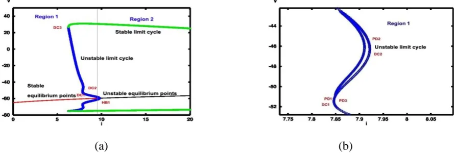
current and for higher values of current. So here the region in figure 16 is divided into three parts
(Region 1, Region 2 and Region 3) to make a clear understanding. Regions for the current values
less than I1 (I=7.9 µA/cm2), I1< I < I2 and for greater than I2 (I=154.5 µA/cm2) are represented by
Region 1, Region 2 and Region 3 respectively. For I>9.7 µA/cm2 system shows an equilibrium
point and a stable limit cycle in region 2, which disappears at I2 (I=154.5 µA/cm2) after a Hopf
bifurcation HB2. Region 3 shows stable equilibrium point higher values of currents. At HB1
bifurcation emanates stable limit cycles (Fig. 17). It can be observed clearly from region 1, that
multistability occurs around HB1. Saddle-node bifurcation occurs at DC1 and DC2 and also it
generates a pair of the stable and unstable limit cycle at DC3 (Fig. 17). As the external applied
current increases, the amplitude of stable limit cycles decrease and abort at I2.
FIGURE 16: Stable (green filled circles) and unstable (blue vacant circles) branches of periodic solution of the HH model showing different dynamical behavior
Coexisting of periodic solutions has occurred at I=9.7 µA/cm2 in which one is stable and the
other three are unstable periodic solutions in region 1. Period-doubling bifurcations occurred at
PD1 and PD2 (Fig. 17(b)). Region 1 shows interesting and complex behaviors of dynamics. Firstly
neuron is at resting state but as the external current is applied to it then it fires an action potential.
Stable and periodic solutions correspond to the resting and firing state of neurons (Fig. 17).
(a) (b)
Now we have analyzed the influence of resting potential of Na on equilibrium points and
bifurcation of the model. It has been observed that membrane potential slowly changes with
respect to Na potential. The system goes under subcritical-Hopf bifurcation at HB1 (VNa=136.4).
Figure 18 gives the relation between V and VNa in which for VNa<136.4 systems gives a stable
solution and for VNa >136.4 system gives an unstable solution.
(a) (b)
FIGURE 18: (a) The relation between membrane potential and parameter
Na
V and (b) Magnification of (a)
Figure 19 gives the relation between V and gNa, and how gNa influences the dynamics of the
system. Figure 19(a) shows that V changes slowly for gNa[0,350] and rapidly for gNa[350,800].
Subcritical-Hopf bifurcation has been observed at HB1. The system shows stable behavior for
gNa<212.6 and unstable behavior for gNa>212.6 [11].
(a) (b)
FIGURE 19: (a) The relation between membrane potential and parameter
Na
Figure 20 gives the relation between V and VK, and how VK influences the dynamics of the
system. Figure 20(a) shows that V changes rapidly with respect to VK. . There are two
Hopf-bifurcation points, HB1 (sub-critical) and HB2 (supercritical). The system shows stable
behavior for VK <-66.89 and VK >-50.32 whereas unstable behavior for -66.89< VK <-50.32
(a) (b)
FIGURE 20: (a) The relation between membrane potential and parameter VK and (b) Magnification of (a)
Figure 21 gives the relation between V and gK, and how gK influences the dynamics of the
system. Figure 21(a) shows that V decreases rapidly with respect to VK. There are two
Hopf-bifurcation points, HB1 and HB2; both are sub-critical Hopf bifurcation points. The system
shows stable behavior for gK <3.844 and gK > 19.76 whereas unstable behavior for 3.844< gK
<19.76 dynamics of the system [11] is very different in Fig. 21.
(a) (b)
We have tried to analyze the effect externally applied current on neuron response. Resting-state
of the neurons corresponds to the stability of the system. When a small pulse of externally applied
current is applied then small perturbation is observed in membrane potential and gating variables,
but it goes to resting state again. A larger pulse of externally applied current causes periodic firing
or spike. The different behavior of externally applied current shows the dynamics of the neurons.
When constant is applied then the system shows stable behavior for lower and higher values of
current and periodic behavior for intermediate values. But when externally applied current is of the
sinusoidal form then we have observed that continuous firing is observed. Chaotic behavior is
observed for lower amplitude and periodic behavior for higher amplitude. We have also observed
synchronization in case of sinusoidal impulse.
Acknowledgments
We would like to acknowledge DST-INSPIRE for financial support.
Conflict of Interests
The authors declare that there is no conflict of interests.
REFERENCES
[1] M. I. Rabinovich, P. Varona, A. I. Selverston and H. D. I. Abarbanel, Rev. Mod. Phys. 78(2006), 1213–1265. [2] L. R. Square, F. E. Bloom, N. C. Spitzer, S. Lac, A. Ghosh, and D. Berg, Fundamental of Neuroscience, Third
edition, Academic Press, Elsevier (2008).
[3] J. Guckenheimer and A. Oliva, Chaos in the Hodgkin–Huxley model, SIAM J. Appl. Dyn. Syst. 1(2002) 105-114.
[4] I. Tasaki, Demonstration of two stable states of the nerve membrane in potassium-rich media, J. Physiol. (London) 148(1959), 306–331.
[6] W. A. Catterall, Voltage‐gated sodium channels at 60: structure, function and pathophysiology, J Physiol. 590 (2012), 2577–2589.
[7] T. Shirahata, Numerical simulation of bistability between regular bursting and chaotic spiking in a mathematical model of snail neurons, Int. J. Theor. Math. Phys. 5(5) (2015), 145-150.
[8] N. I. Krouchev, F. Rattay, M. Sawan, and A. Vinet, From squid to mammals with the HH Model through the Nav channels’ half-activation-voltage parameter, PLoS ONE, 10(12) 2015, e0143570.
[9] B. Kashef and R. Bellman, Solution of the partial differential equation of the Hodgkin-Huxley model using differential quadrature, Math. Biosci.19(1974), 1-8.
[10] B. Hassard, Bifurcation of periodic solutions of the Hodgkin-Huxley model for the squid giant axon, J. Theor. Biol. 71(3) (1978), 401–420.