Turkish Journal of Fisheries and Aquatic Sciences 17: 257-268 (2017)
www.trjfas.org ISSN 1303-2712 DOI: 10.4194/1303-2712-v17_2_04
RESEARCH PAPER
© Published by Central Fisheries Research Institute (CFRI) Trabzon, Turkey in cooperation w ith Japan International Cooperation Agency (JICA), Japan
Structural Analysis of Float Collar for Metal Fish Cage in Waves
Introduction
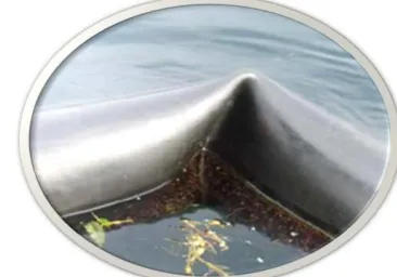
Fish farms are recently forced to move into the offshore area, and this makes a challenge for the design of fish cage structure, especially for the structural analysis of float collar for the gravity cage. The float collar for grav ity cage is the primary component to withstand the wave force, and its design plays an important role for the safety of the fish cage structure (see Figure 1). Therefo re, it is necessary to analyze the deformat ion and the stress of the float collar, wh ich is the basis for the design and safety assessment of the fish cage system.
To our knowledge, several researches were conducted to analyze the dynamic response of fish cage in the open sea. So me studies including numerical simu lation and physical model test were focused on the hydrodynamic behavior of net cages in waves and currents. Ormberg (1991) e xtended the e xisting FEM progra m RIFLEX (SINTEF, 1987) to perform dyna mic , nonlinear analysis of floating fish farms in regula r waves. Tsukrov et al. 2003 proposed a numerical mode l to analyze the hydrodynamic response of net panels to environmental loading with the concept of consistent finite e le ment. Lader and Fredheim 2006 investigated dynamic properties of a
fle xib le net sheet exposed to waves and current by numerical simu lation, in wh ich the net was modeled by dividing it into super ele ments. Kristiansen and Faltinsen 2012 proposed a screen type of force model for the v iscous hydrodynamic load on nets, in which the net is divided into a number of flat net panels, or screens. Li et al. 2013 investigated the nonlinear hydroelastic response of a deep-water gravity aquaculture fish cage in irregular waves. Fu et al. 2013 investigated the hydrodynamic characteristics of a floating cylinder for fish cage by the force oscillation experiments in towing tank.
In addition, the mechanical performance of n et materia l used in the fish cage structure was also analyzed. Sa la et al. 2004 investigated experimentally the differences in breaking load and elongation of knotless netting before and after use. Moe et al. 2007 established a new method to investigate th e tensile stiffness properties of knotless netting material. Moe et al. 2008 investigated the temporary-creep properties, recovery of strain post creep and post -creep tensile properties of a selection of Raschel knitted netting materials.
Furthermore, Suhey et al. 2005 presented a numerical simulat ion of an inflatable open -ocean-aquaculture cage using nonlinear finite ele ment
Tiao-Jian Xu
1,2, Hui-Min Hou
1, Guo-Hai Dong
1, Yun-Peng Zhao
1, Wei-Jun Guo
31
State Key Laboratory of Coastal and Offshore Engineering, Dalian University of Technology, Dalian 116024, China. 2School of Naval Architecture and Ocean Engineering, Dalian University of Technology, Dalian 116024, China. 3 Environmental Science and Technology College, Dalian M aritime University, Dalian 116026, China.
* Corresponding Author: Tel.: +86.411 84708514; Fax: +86.411 84708526; E-mail: [email protected]
Received 28 October 2015 Accepted 07 September 2016
Abstract
Float collar is an important component for the fish cage systems which are applied by the aquaculture industry. The integrity and reliability of the float collar are detrimental in order to avoid the critical failure which may lead to major loss and severe consequences. A finite element model for the structural analysis of the float collar for the metal fish cage in waves is developed and validated by comparing with the experimental data. The numerical simulation is performed to conduct the parametrical study of float collar and to analyze the deformation and the stress of a met al fish cage in waves. The results indicate that the numerical model can accurately predict the deformation of float collar and the tension force on mooring line. When the central angle of the arc between two neighboring clamps is larger than 15°, the influence of the amount of clamps on the deformation of float collar is decreased significantly. For the metal fish cage structure, the upper part of the nets for the metal fish cage experiences the largest deformation, and thus the diameter of the net twine at the upper part of the metal fish cage should be increased to avoid the structural failure.
258
analysis of me mbrane structures, and the finite ele ment model is validated using a modified bea m theory for the inflatable structure by comparing the ma ximu m deflect ion and stress. Fredriksson et al. 2007 developed a fin ite-ele ment modeling technique to determine the structural capabilities of net pens, in which the c rit ical loading conditions are predicted. Dong et al. 2010 p roposed an analytical method to investigate the elastic deformations of a c ircula r ring subjected to water waves, based on the Euler’s laws and the curved beam theory. Xu et al. 2014 ana lyzed the fatigue damage of mooring line for net cage using the rainflow counting method and the spectrum analysis method. Kim et al. 2014 analy zed the flow fie ld characteristics within the abalone contain ment structure with co mputational fluid dynamic software, in addit ion, the structural analysis of the deploy ment and recovery operation was also investigated.
Recently, the metal net cage has received much attention from the researcher due to such advantages as the protection fro m predators, the better cage volume retention, and the good resistance to bio -fouling. Tsukrov et al. 2011 conducted a series of e xperiments to analyze the drag forces on copper alloy net panels, and proposed the empirica l values for norma l drag coefficients for various types of copper netting. Cha et al. 2013 analy zed the drag and lift coefficients of copper alloys and fabric nets, and observed the flow through the fish net using particle image velocimetry (PIV). However, the e xisting research has never concerned with the structural analysis of the fish cage with metal nets. The research on the deformation and the stress of the float collar with metal fish net under the action of waves is very limited, and the bending stiffness of fish net is usually neglected in the previous numerical mode l developed for fish cage. Therefore, it is necessary to develop a numerical mode l for ana lyzing the structural performance of the float collar with metal fish net in waves. Thus, the finite e le ment technique is used to build the numerical mode l for the structural analysis of float collar with metal fish nets in waves here, in which the dynamic load test is performed. In this study, the numerica l simu lation for the structural
analysis of the float collar with metal fish nets was conducted, and the parametrica l study of the float collar was also performed.
The paper is organized as follows. Section 2 presents a description of the nume rica l method for the structural analysis of the float collar with metal nets in waves. Section 3 describes a physical model test of a float colla r and mooring system and presents the comparison results between the numerica l simulat ion and the physical model tests. In Section 4, the parametrica l study of float collar in waves is performed and the structural analysis of a metal fish cage is also conducted. Finally, Sect ion 5 summarizes some conclusions.
Method
The finite e le ment model of the float colla r with meta l nets in waves was described here. The load -deformation model for the structural analysis of float collar in waves was developed in the commerc ially available software ANSYS, and the p ipe e le ment is applied to simulate the float colla r and the link element is used to model the mooring lines
Governing Equation
Transient dynamic analysis is a technique used to determine the dyna mic response of a structure under the action of any general time -dependent loads. This analysis can be used to determine the time -varying displacements, strains, stresses, and forces in a structure as it responds to any comb ination of static, transient and harmonic loads. The basic equation of motion solved by a transient dynamic analysis is as follows,
M R
C R
K R
F t
( )
P t
( )
(1)where R is the nodal d isplacement vector,
R
is the nodal velocity vector,R
is the nodal acceleration vector, M is the mass matrix, C is the da mping matrix, K is the stiffness matrix, F(t) is the equivalent nodal259
force vector due to relative flu id motion, the wave and current loads, P(t) is the equivalent nodal force due to gravity and buoyancy forces. The Newmark t ime integration method is applied to solve these motions at discrete time points.
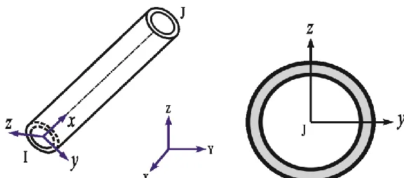
For the fin ite ele ment model of the float colla r with metal nets, the pipe ele ment is applied to simu late the floating pipe and the link e le ment is used to model the mooring line. The p ipe ele ment applied here is a unia xia l e le ment with tension-compression, torsion, and bending capabilit ies, and with the me mbe r forces simulat ing the ocean waves and current. The pipe ele ment has six degrees of freedo m at each node: translations in the nodal x, y, and z directions and rotations around the nodal x, y, and z a xes. The e le ment loads include the hydrodynamic and buoyant effects of the water, and the element mass includes the added mass of water and the pipe internals. In addition, the pipe element was simplified to simu late the cage net structure, in which the inner dia meter of the pipe ele ment is set to be zero for simu lating the nets and the bending stiffness of the nets is also considered in the numerica l model. The geometry, node locations, and the coordinate system for this element are shown in Figure 2.
Environmental Loading
The hydrodynamic load acting on the floating pipe is calcu lated fro m a generalized Morison’s equation. To simplify the nu merica l mode l, each ele ment is treated as a small body since the element size is relat ively sma ll compared with the characteristic wavelength. This means that the scattering effect between the structural ele ment and the flow fie ld can be neglected. Thus, it is appropriate to apply the modified Morison equation including the relative mot ion between the structural ele ment and the surrounding fluid, as follows:
0 0
1
(
)
(
)
2
D mF
C A u R u R
V a C V a R
(2)where u and
R
are the velocity vectors for the water partic les and the structural ele ments,respectively; a and
R
are the acceleration vectors forthe water partic les and the structural ele ments, respectively; ρ is the density of water; V0 is the water displaced volume of a structural ele ment; A is the effective p rojected area of a structural e le ment, and CD and Cm are the drag and added mass coefficients, respectively. The hydrodynamic coeffic ients of float collar a re taken as constants: the drag coefficients are chosen as CD=0.4; and the added mass coeffic ients are chosen as Cm=0.2.
Description of Wave Field
Based on linear wave theory, the velocity potential of the wave is given by
cosh (
)
sin(
2
)
2
cosh
g
k d z
A
kx
ft
f
kd
(3)Surface elevation,
cos(
2
)
A
kx
ft
(4)and dispersion relation,
2
(2
f
)
gk
tanh(
kd
)
(5)where A is the wave amp litude, g is the gravitational accele ration, f is the wave frequency, k is the wave numbe r (equal to2π/L ), L is the wave length, d is the water depth, z is the vertica l d istance (positive upward) from mean-water level.
Metal Fish Cage Model
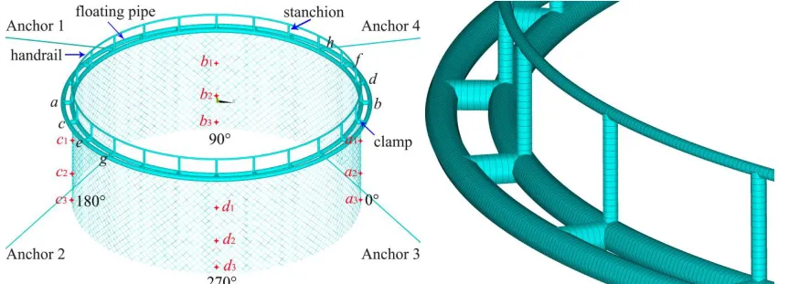
The metal fish cage has received much attention due to its strong anti-wave and anti-current performance. A typical t wo-ring metal fish cage in Figure 3 is usually composed of floating pipe, handrail, stanchion and clamps. The cla mps between the rings keep them at correct distance, and the inner ring (dia mete r = 15.92 m) is connected with the outer ring (d ia meter = 16.92 m) by a series of cla mps. The center to center distance between the rings is 0.5 m.
260
The two rings are made of pipes with identical cross -section properties: dia meter: 25 c m, wa ll thickness: 1.3 c m, modulus of e lasticity: E = 667 Mpa, density: 953 kg/ m3. The c la mps are mode led assuming a pipe of HDPE with c ircula r c ross -section with radius of 25 cm. The stanchion with he ight of 1 m is used to link the handrail and the inner ring. There a re 3648 nodes and 3696 p ipe e le ments in the fin ite ele ment model of float colla r, and the ma ximu m mesh size of the pipe element is 2 cm.
There are 120 meshes in the circumferentia l direction and 15 in the depth direction for the fish net. The net is knotless, with a mesh size of 59 mm and a twine thickness of 2.4 mm. When mounted as dia mond meshes, the net forms an open vertical cylinder with a dia meter of 15.92 m and a height of 6.258 m. The net is attached to the float collar, and the mass density of the metal fish net is 7.85×10³ kg/m3. The metal fish cage is anchored to the sea floor by the four mooring lines. The water depth is 20 m, and the coordinates of the four anchor points are (50, 50, -20), (-50, 50, -20), (-50, -50, -20), (50, -50, -20), respectively.
Physical Model Test
A series of physical model tests were conducted to validate the nume rica l model for the structural analysis of float collar fo r fish cage in waves. The model test includes two parts: the structural analysis of the circular ring and the hydrodynamic response of
float collar in waves.
Circular Ring Experiments
To validate the fin ite e le ment model fo r the structural analysis the float colla r in waves, a set of e xperiments were conducted using circular rings of HDPE p ipe. Tests were firs t conducted in the laboratory, and then the numerical simu lations were performed using the FEM technique.
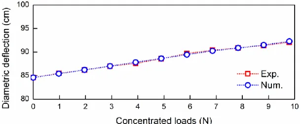
The 84.6 c m dia meter c ircula r ring of HDPE pipe (pipe d ia meter = 15.32 mm, pipe thic kness = 1.33 mm) is tested in the laboratory experiment, the ring was fixed at two locations on one side spaced approximately 59.8 c m (a long the arc). On the other side, a single rope with an in line load cell was attached to the ring. A photograph of the setup is shown in Fig. 4a. The defo rmation of the c ircula r ring under the action of the concentrated load is shown in Figure 4. The ne xt step was to perform nu me rica l simu lations of the circular ring laboratory tests and compare the results. The finite e le ment model of the circula r ring was constructed using the geometric properties of the pipe fro m the circula r ring laboratory tests. The deformation of the c ircu lar ring fro m the numerical simu lation is also shown in Fig. 3. The results indicate that the shapes of circula r ring fro m the numerical simu lation a re simila r with those fro m the physical model test.
The quantitative comparison of the d ia metric deflection between the numerical simu lation and the
Figure 3. The finite element model of the fish cage with metal nets.
261
physical model test is also presented here. As shown in Figure 5, the measured tension is plotted as a function of d ia metric deflection of the circular ring. It indicates that the fin ite e le ment mode l is appropriate to investigate the deformation of circula r rings under external loads.
Float Collar in Waves
To validate the fin ite e le ment model for the float collar in waves, the numerica l simulat ion for the hydrodynamic response of float colla r in waves was performed and co mpared with the physical model tests (Figure 6). The tests were conducted in the wave-current basin at the State Key Laboratory of Coastal and Offshore Engineering of the Da lian University of Technology, China. The wave-current basin is 69 m long, 2 m wide and 1.8 m high. The SG800 wave probe produced by the China Institute of Water Resources and Hydropower Research is applied to measure wave height and period, with measuring range of 0-35 c m and re lative erro r of 0.5%. The DJ800 with the measuring range is 0-10 N is adopted to measure the tension force on mooring line.
The float colla r model should meet the geometric similarity, kine mat ic simila rity and dynamic similarity. However, it is difficult to complete ly meet the simila rity law. Because the float collar is usually at the surface of water, the double floating pipes are the main co mponents to withstand the hydrodynamic force. There fore, the float colla r is simp lified into double concentric pipes in the physical model test. The float colla r mode l is designed to satisfy the geometric similarity and gravity similarity. The detailed para meters of the float collar are g iven in Table 1 and Table 2.
Measurements of the mooring line forces we re obtained using a submersible, ring-type load cell, which is attached to the bottom of the anchor lines. An optical measurement system was developed to determine the float collar mot ions. Two diodes were fixed on the float co lla r for motion analysis, as shown in Fig. 6. A charge coupled device (CCD) ca mera recorded the movements of d iodes. The ca mera captures a series of images and transfers each frame to the computer and temporary storage. Later, specially written software is used to search the position of diodes, which is used to calculate the float collar horizontal and vert ical move ments as functions of
Figure 5. The diametric deflection of a circular ring under the action of point loads.
262
time. The regula r waves propagated along the positive x-direction. The details of regular wave conditions are presented in Table 3.
The calculated and e xpe rimental results were quantitatively compared to validate the nume rica l model. The mooring line tension force and the float
Table 1. Geometry and material parameters of float collar
Component Parameter value
Outer circle General diameter (m) 0.846
Pipe inner diameter (mm) 15.32
Pipe outer diameter (mm) 12.66
Density (g/cm3) 0.953
M aterial HDPE
Inner circle General diameter (m) 0.796
Pipe inner diameter (mm) 15.32
Pipe outer diameter (mm) 12.66
Density (g/cm3) 0.953
M aterial HDPE
Table 2 M echanical parameters of HDPE used in the float collar
Parameter Value
Elastic modulus 667MPa
Yield limit 24.1M Pa
Poisson ratio 0.41
Density 953 kg/m3
Table 3 Wave parameters for numerical simulation and physical model test
No. 1 2 3 4 5 6 7 8 9 10 11 12
Wave period T (s) 1.2 1.4 1.6 1.4 1.6 1.8 1.4 1.6 1.8 1.6 1.8 2.0 Wave height H (cm) 20 20 20 25 25 25 29 29 29 34 34 34
Figure 7. The tension force on anchor line from the numerical simulation and physical model test .
263
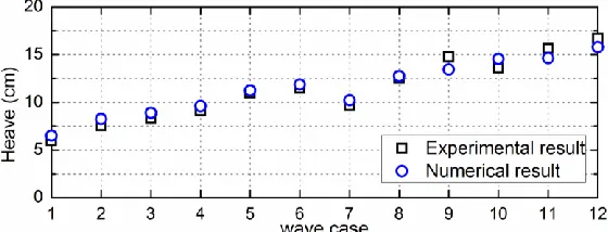
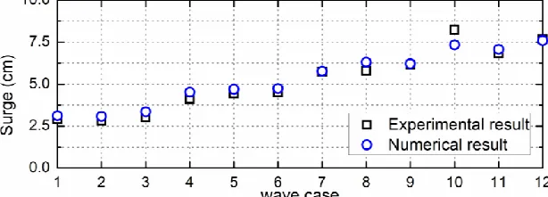
collar mot ion are selected for co mparison. For the mooring line tension force, the designer of th e fish cage and mooring system is ma inly focused on the ma ximu m value of the mooring line tension force. Figure 7 shows the comparisons of the ma ximu m mooring line tension force obtained from the calculated results and e xperimental data. Figures 8 and 9 compare the ma ximu m vert ical and horizontal displacements of the float collar obtained fro m the calculated results and experimental data, respectively.
The relative e rror is given by ε=(Vs-Vm)/Vm,
where Vs and Vm are the ma ximu m mooring line
tension forces and the motion responses of float collar obtained from the nu merical simulat ion and the physical mode l test, respectively. For the ma ximu m mooring line tension force, the ma ximu m re lative error is 8.7% and the mean value of the re lative error is 4.6%. For the motion response of the float collar, the ma ximu m e rrors of the vertical and horizontal displacements of the float collar are 9.2% and 10.6%, respectively. The mean relat ive errors of the vertical and horizontal displace ments of the float collar are 5.9% and 6.2%, respectively.
The calculated results of the tension forces on mooring line and the mot ions of float collar correspond well with the e xperimental data, with the relative errors of approximately 11%. Based on the above analysis, the numerica l model presented here can be used in the structural analysis of the float collar under the action of waves.
Results and Discussion
The numerical simu lation for the structural
analysis of the float collar in waves is performed to analyze the deformat ion and the stress of the float collar. The para metrica l study of the float collar is conducted, and then the structural analysis of a metal fish cage is also performed. A 2 m wave with period of 6 s is applied here.
Effect of the Amount of Connectors
The a mount of connectors including the c la mp and the stanchion will a ffect the deformation of float collar, it is necessary to choose an appropriate amount of connectors. The central angle θ of an arc between the neighboring connectors for different a mount of connectors (18, 24, 30 and 36) is equal to 20°, 15°, 12° and 10°, respectively.
The deformation rate Cab=(lab-D)/D is applied to represent the deformation of float collar, where D is the diameter o f float colla r, lab is the ma ximu m value of the distance between the points a and b, and the initia l value of lab is equal to the diameter of float collar. The points a, b, c, d, e, f, g and h a re ma rked in Fig. 3 for cla rity of the description. Similarly, the deformation rate Ccd, Cef and Cgh can also be obtained. The deformation Cab of float collar with different amount of connectors is shown in Figure 10. When the amount of connectors is 18, 24, 30 and 36, the deformation rate Cab of float collar is 1.8%, 1.32%, 1.3%, and 1.27%, respectively. It indicates that with the increase in the a mount of connectors, the deformation of float collar is decreased significantly. When the central angel θ is larger than 15° (i.e. the amount of connectors is 24), the influence of the amount of connectors on the deformation of the float
Figure 9. The surge motion of float collar from the numerical simulation and physical model test.
264
collar is becoming smaller.
The ma ximu m stress on the float collar is a lso calculated and shown in Figure 11. The results indicate that the ma ximu m stresses on the inner ring and the outer ring are generally decreased with the increase in the amount of connectors. As the increase in the a mount of connectors, the deformation of float collar is decreased, and thus it is reasonable that the ma ximu m stress on the float collar is also decreased with the increasing amount of connectors.
Effect of the Bending Rigidity of Connectors
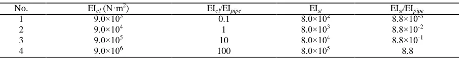
In order to reduce the deformation of float colla r in waves, the float collar must have sufficient bending stiffness. The relative rigidity between the connector and the floating pipe will affect the deformation mode of float colla r, and thus different rigidit ies of connector are considered, as shown in Table 4.
The deformat ions of float collar with different rig idities of connectors are shown in Figure 12. The deformation of float collar in waves includes the in -plane deformation and the out-of--plane deformation. The results indicate that the re lative rigidity between the connectors and the floating pipes has significant influence on the in-plane deformat ion; however, its influence on the out-of-plane deformation is re latively small. The deformation of float collar is increased with the decrease in the bending stiffness of connectors. The out-of-plane deformat ion is la rgest as the wave crests or the wave troughs pass through the center of float co lla r, in addition, the ele ment of floating pipe connected with the mooring line
experiences the largest bending deformation.
The deformation of handrail is also increased with the decrease in the bending stiffness of connectors as shown in the fourth row of Fig. 12. It is reasonable because the bending stiffness of the float collar is decreased as the bending stiffness of connectors is decreased, and thus the deformat ion of float collar is increased. The handrail for th e float collar is generally located above the water surface, and thus the double floating pipes are the ma in component to withstand the hydrodynamic force. When a larger de formation of float collar occurs, more o f the hydrodynamic loads acting on the double floating pipes can be transferred into the handrail.
Effect of the Tensile Stiffness of Mooring Line
The float colla r is anchored to the sea floor by mooring line. Different stiffness values of mooring line are considered here, and the tensile stiffnes s (K=EA/l) of mooring line is set as 1.1×10², 1.1×10³, 1.1×10⁴, 1.1×10⁵, 1.1×10⁶
N/m, respectively. The ma ximu m tension force on the mooring line and the dia metrica l defo rmation of float colla r fo r diffe rent tensile stiffness values of mooring line are calcu lated and compared, as shown in Figure 13. The results indicate that the ma ximu m tension force on mooring line is increased significantly with the increase in the tensile stiffness of mooring line. The deformat ion rate of float collar is also increased with the increasing tensile stiffness of mooring line. It means that as long as the breaking strength of mooring line is enough, it is better to select a lower moo ring line tensile stiffness
Figure 11. M aximum stress on the float collar with different amount of connectors.
Table 4 Bending stiffness of the connector and the floating pipe
No. EIcl (N·m2) EIcl/EIpipe EIst EIst/EIpipe
1 9.0×10³ 0.1 8.0×10² 8.8×10⁻³
2 9.0×10⁴ 1 8.0×10³ 8.8×10⁻²
3 9.0×10⁵ 10 8.0×10⁴ 8.8×10⁻¹
4 9.0×10⁶ 100 8.0×10⁵ 8.8
265
to reduce the structural response of float collar in waves.
Different Wave Incident Direction
Note that the waves propagated along various directions in the open sea, and it will a ffect the
structural response of float co lla r structure. Thus, four different wave d irections (0°, 15°, 30° and 45°) are considered in v iew of the symmetrical characteristics of the fish cage and mooring system. The deformat ion rates Cab, Ccd, Cef and Cgh of the float colla r (see Fig. 3) are ca lculated for d iffe rent wave incident
No. 1 No. 2 No. 3 No. 4
0.25T
0.50T
0.75T
1.00T
0.25T
0.50T
0.75T
1.00T
Figure 12. The deformation of float collar with different rigidity of connectors.
Figure 13 The maximum tension force on mooring line and the deflection of float collar with different stiffness of mooring line.
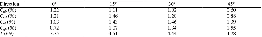
Table 5 The deformation rate of float collar and the maximum tension force on mooring line for different wave incident directions
Direction 0° 15° 30° 45°
Cab (%) 1.22 1.11 1.02 0.60
Ccd (%) 1.21 1.46 1.20 0.88
Cef (%) 1.03 1.43 1.46 1.39
Cgh (%) 0.72 1.07 1.34 1.55
266
directions, as shown in Table 5. The results indicate that the largest deformation of float collar is always occurred in the wave inc ident direction. When the wave inc ident direction is along the mooring lines, the deformation of float collar is la rgest. The ma ximu m tension forces on mooring line are a lso presented in Table 5. When the wave incident angle is 45°, the maximu m tension force on mooring line is largest.
Fish Cage with Metal Nets
Figure 14 shows the ma ximu m stress on the net for the meta l fish cage at different points marked with star shape in Fig. 3. The results indicate that when the depth is larger than 4.2 m, the variation of the ma ximu m stress on the net for the meta l fish cage is small, and the ma ximu m stress on the upper part of the net is obviously larger than that for the lower part of the net. Thus , only the twine diameter at the upper part of the nets for the metal fish cage should be increased.
The deformat ions of the nets for the metal fish cage in waves at four representative mo ments are calculated and shown in Figure 15. The results indicate that the upper part of the net for the metal fish cage experiences the largest deformat ion, which is consistent with the stress distribution on the cage net. The deformat ion of the lo wer part of the net for the metal fish cage is small, which is obviously diffe rent fro m that for the fle xible net cage (Xu et al.
2013). In addition, when the wave crest and the wave trough pass through the center of the fish cage, the largest out-of-plane deformation of the float collar occurs, which significantly affect the deformation of the cage net.
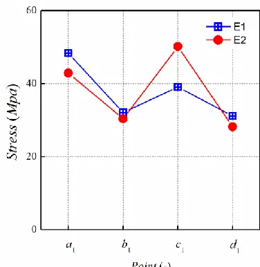
The bending stiffness of float colla r will a ffect the out-of-plane deformat ion of float collar in waves. To know how the deformation of float collar will influence the deformat ion and the stress of the fish net for the metal fish cage, and thus two kinds of bending stiffness of the float colla r (E1=667 Mpa, E2=6670
Mpa) are considered here. Figure 16 presents the ma ximu m stress on the fish net at points a1, b1, c1 and
d1 (see Fig. 3) for t wo kinds of bending stiffness of
the float collar, respectively. The results indicate that the bending stiffness of the float colla r significantly affect the ma ximu m stress on the fish net at point c1,
however, the influence of the bending stiffness of float collar on the stress on the fish net at points b1
and d1 is relatively s mall. Based on the above
analysis, the fish farmer should strengthen to detect the deformation and the stress of the upper part of the metal fish cage.
Conclusions
Transient finite ele ment analysis of a metal fish cage and mooring system in waves is performed to analyze the deformation and the stress of the metal fish cage. A series of physical model test is conducted
Figure 14. The distribution of the maximum stress on the cage net at different position.
267
to validate the numerica l model. The results indicate that the numerical mode l is suitable for analyzing th e deformation of float collar and the tension force on mooring line. The pa ra metrical study of float collar shows that the effect of the a mount of connectors on the deformation of float colla r is becoming sma ller when the central angel θ o f the arc between two neighboring connectors is larger than 15°. The out-of-plane deformation of the float collar is most serious as the wave crests and the wave troughs pass through the center of float collar. The la rgest deformation of float collar is always occurred in the wave incident direction. The ma ximu m stress on the upper part of the net for the metal fish cage is significantly la rger than that for the lower part of the net, and the deformation of the metal fish-cage is prima rily occurred at the upper part of the net. The fish farme r should strengthen to detect the stress and deformat ion of the upper part of the net for the metal fish cage.
Acknowledgements
This work was financially supported by the National Natural Sc ience Foundation (NSFC) Projects No. 51409037, 51239002, 51579037, and 51221961, China Postdoctoral Science Foundation (No.2014M560211 and No.2015T80254), the Fundamental Research Funds for the Central Universities No. DUT16RC(4)25, and Cult ivation plan for young agriculture science and technology innovation talents of Liaoning province (No.2014008).
References
Cha, B.J., Kim, H.Y., Bae, J.H., Yang, Y.S., Kim, D.H., 2013. Analysis of the hydrodynamic characteristics of chain-link woven copper alloy nets for fish cages. Aquacultural Engineering 56, 79-85. DOI:
10.1016/j.aquaeng.2013.05.002
Dong, G.H., Hao, S.H., Zhao, Y.P., Zong, Z., Gui, F.K., 2010. Elastic responses of a flotation ring in water waves. Journal of Fluids and Structures 26(1), 176-192. DOI: 10.1016/j.jfluidstructs.2009.09.001 Fredriksson, D.W., Decew, J.C., Tsukrov, I., 2007.
Development of structural modeling techniques for evaluating HDPE plastic net pens used in marine aquaculture. Ocean Engineering 34, 2124-2137. DOI: 10.1016/j.oceaneng.2007.04.007
Fu, S.X., Xu, Y.W., Hu, K., Zhang, Y., 2013. Experimental investigation on hydrodynamic of floating cylinder in oscillatory and steady flows by forced oscillation test. M arine Structures 34, 41-55. doi:10.1016/j.marstruc.2013.08.005
Kim, T., Lee, J., Fredriksson, D.W., DeCew, J., Drach, A., 2014. Engineering analysis of a submersible abalone aquaculture cage system for deployment in exposed marine environments. Aquacultural Engineering 63, 72-88. DOI: 10.1016/j.aquaeng.2014.10.006
Kristiansen, T., Faltinsen, O.M ., 2012. M odelling of current loads on aquaculture net cages. Journal of Fluids and Structures 34, 218-235. DOI: 10.1016/j.jfluidstructs.2012.04.001
Lader, P.F., Fredheim, A., 2006. Dynamic properties of a flexible net sheet in waves and current-A numerical approach. Aquacultural Engineering 35(3), 228-238. DOI: 10.1016/j.aquaeng.2006.02.002
Li, L., Fu, S.X., Xu, Y.W., 2013. Nonlinear hydroelastic analysis of an aquaculture fish cage in irregular waves. M arine Structures 34, 56-73. DOI: 10.1016/j.marstruc.2013.08.002
M oe, H., Hopperstad, O.S., Olsen, A., Jensen, Fredheim, A., 2008. Temporary creep and post creep properties of aquaculture netting materials. Ocean Engineering
36(12-13), 992-1002. DOI:
10.1016/j.oceaneng.2009.05.009
M oe, H., Olsen, A., Hopperstad, O.S., Jensen, Ø., Fredheim, A., 2007. Tensile properties for netting materials used in aquaculture net cages. Aquacultural Engineering 37(3), 252-265. DOI: 10.1016/j.aquaeng.2007.08.001 Ormberg, H. (1991). Non-linear response analysis of
floating fish farm systems. PhD thesis, Division of
268
M arine Structures, Norwegian Institute of Technology, University of Trondheim.
Sala, A., Lucchetti, A., Buglioni, G., 2004. The change in physical properties of some nylon (PA) netting samples before and after use. Fisheries Reserach 69, 181-188. DOI: 10.1016/j.fishres.2004.05.005
Suhey, J.D., Kim, N.H., Niezrecki, C., 2005. Numerical modeling and design of inflatable structures – application to open-ocean-aquaculure cages. Aquacultural Engineering 33, 285-303. DOI: 10.1016/j.aquaeng.2005.03.001
Tsukrov, I., Drach, A., Decew, J., Swift, M .R., Celikkol, B., 2011. Characterization of geometry and normal drag coefficients of copper nets. Ocean Engineering 38, 1979-1988. DOI: 10.1016/j.oceaneng.2011.09.019
Tsukrov, I., Eroshkin, O., Fredriksson, D., Swift, M .R., Celikkol, B., 2003. Finite element modeling of net panels using a consistent net element. Ocean Engineering 30(2), 251-270. DOI: 10.1016/S0029-8018(02)00021-5
Xu, T.J., Zhao, Y.P., Dong, G.H., Bi, C.W., 2014. Fatigue analysis of mooring system for net cage under random loads. Aquacultural Engineering 58, 59-68. DOI: 10.1016/j.aquaeng.2013.10.004